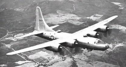
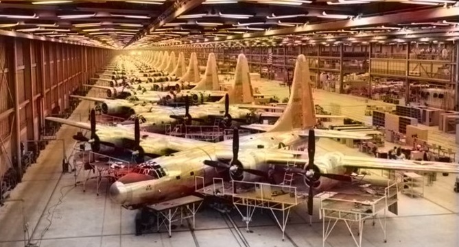
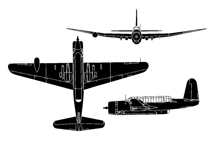
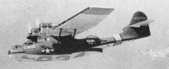
The B-32 was initially intended as insurance against failure of the B-29 program. Consolidated were awarded a contract for the XB 32 at the same time as Boeing were given the XB 29, but the first prototype, (Model 33) did not fly for two years, the first XB 32 taking the air on September 7, 1942. In configuration a much bigger development of the Model 32 Liberator, the Model 33 had four 2200 hp Wright R 3350 23 Duplex Cyclone engines, each with two GE turbo-superchargers, driving four blade Curtiss Electric propellers. The fuselage was of more circular section than that of the Liberator, and all crew compartments were pressurized. The nose was like that of the B 29, and the tail had twin fins similar in shape to the Liberator. Unlike the Liberator, the main gears had twin wheels and retracted forward into the inner nacelles (the four nacelles were large and extended aft of the trailing edge). Armament comprised two 20 mm (0.79 in) cannon and 14 03 in (12.7 mm) guns in remote control barbettes. However, the success of B-29 development and operational deployment made cancellation of the Dominator a very real possibility at several points in its development. Because the B-32 test program was so far behind schedule, not a single B-32 was ever sent to the Mediterranean or European Theaters of Operation. Technical difficulties were severe. The second XB, flown on July 2, 1943, had a conventional nose with stepped pilot windscreens. The third, flown on November 9, 1943, followed the late model Liberators in switching to an extremely large single fin and rudder. Large scale production was planned, and orders were placed for 1700 production B 32 Dominators. However, technical difficulties continued, and to get the programme moving the pressurization and complex remote control armament were abandoned at a late stage. The B 32 was produced as a strategic bomber cast in the mould of the B 24 Liberator with a typical over target height of not above 8534 m (28 000 ft). In December 1944, the B-32 program was almost canceled again. This time it was saved pending completion of a service test program. As put into production in the spring of 1944, the B 32 had five turrets, each housing a gunner and mounting twin .03 in (12.7 mm). Internal bomb bays under the wing spans carried 9072 kg (20 000 lb) of bombs. Up to ten 12.7mm (.50 caliber) M2 heavy machine guns were provided for self-defense and mounted in pairs in turrets. A Sperry electric-hydraulic ball turret was mounted in the nose along with two Martin electrically-operated dorsal fuselage turret positions and a Sperry retractable turret in a ventral position. A Sperry tail ball turret protected the rear.
Deliveries began in November 1944, 40 TB¬-32 crew trainers were used to train crews. While the service test proceeded, combat crew training was started in preparation for deployment to the Pacific (pending a successful service test.) The service test revealed several minor and a few major problems and the program was near cancellation once again in the spring of 1945. In March 1945, General George Kenney, Commander of the Far Eastern Air Forces (5th AF), traveled to Washington D.C. to ask for B-32s. He wanted B-29s but was turned down because of higher priority needs elsewhere in the PTO. After demonstrations in Washington, General Kenney convinced the Army General Staff to allow him to conduct a combat evaluation of the Dominator. A combat test plan of eleven missions was planned and if successful, the B-32 was scheduled to replace all the B-24 groups in the Pacific Theater. Three B-32s were assigned to the 386th Bomb Squadron, 312th Bomb Group, 5th Air Force. The first combat test mission was flown against a supply depot at Antatet, Luzon, Philippines on 29 May 1945. The last mission of the generally successful combat test was flown on 25 June 1945 against bridges near Kiirun on the island of Formosa (Taiwan).
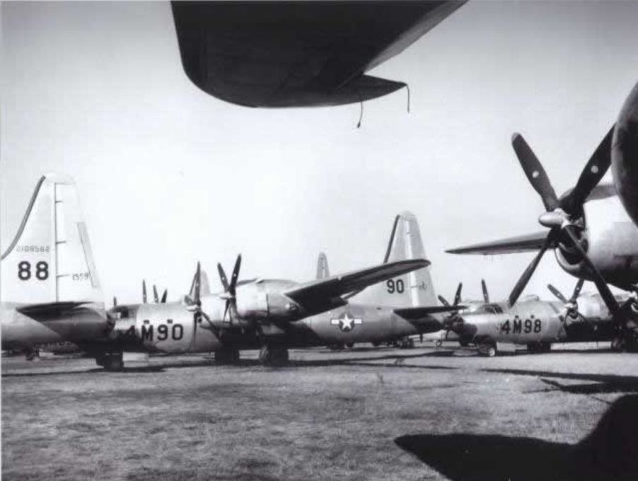
The 386th Bomb Squadron completed B-32 transition in July 1945 and flew six operational combat missions before the end of the war. The most used Consolidated B-32 Dominator aircraft operationally were three B-32-20-CF’s (Serial Nos 42-108528, 42-108529 ‘The Lady is Fresh’ and 42-108532 ‘Hobo Queen II’). These machines were assigned to the 386th Bombardment Squadron, 312th Bombardment Group (Light) and operated from Clark Field and Floridablanca in the Philippines from May 29th to July 6th, 1945. During this period they undertook twelve bombing missions and dropped 134 tons of bombs on enemy positions. On the 11th August 42-108528 and 42-108532 moved to Yontan Air Base on Okinawa and in so doing joined another five B-32s that were already stationed there.
Following the 9 August 1945 bombing of Nagasaki, the 386th conducted photo reconnaissance missions and during a photo-reconnaissance sortie near Tokyo on the 17th August ‘Hobo Queen II’ and three other B-32s were attacked by ten Japanese fighters. The quartette defended themselves well and one Japanese fighter was shot down with another two claimed as probables. Furthermore, on the 18th August the ‘Hobo Queen II’ and 42-108578 shot down two Japanese aircraft over Tokyo and claimed two more as probables. Although no Dominator was lost in combat, at least two were damaged. Sergeant Marchione, a photographer aboard one of the B-32s on the photo reconnaissance mission of 18 August 1945, was killed when his bomber was attacked by fighters.
The last B-32 combat mission (also photo recon) was completed on 28 August 1945. The 386th BS was ordered to cease combat operations two days later. Cancellation of the B-32 program came on 8 September 1945 and production of Dominators was halted on 12 October.
By VJ Day 115 B 32s had been delivered, 1588 being cancelled and the type withdrawn from service.
Flyable aircraft at Consolidated factories were flown directly to the scrap yard and all partially built B-32s were scrapped at the factory. The last remaining B-32 was scrapped in the summer of 1949.
Number Built: 75 Serial numbers: 42-108471 to 42-10884; 42-108525 to 42-108584; 44-90486 74 B-32s built at the Consolidated Fort Worth, Texas plant. 1 B-32 built at the Consolidated San Diego, California plant. 3 XB-32s and 40 TB-32s were built A total of 118 B-32 built of all types
Consolidated B-32 Dominator Engines: 4 x Wright R-3350-23 Duplex Cyclone 18-cylinder air-cooled turbocharged radial, 2,200hp, 1641kW Propellers: Curtiss Electric reversible-pitch four-blade Length: 83 ft 1 in (25.3m) Wingspan: 135.17ft (41.20m) Wing area: 132.1 sq.m / 1421.91 sq ft Wing load : 78.52 lb/sq.ft / 383.0 kg/sq.m Height: 33.14ft (10.10m) Empty Weight: 59,525lbs (27,000kg) Maximum Take-Off Weight: 50576 kg / 111502 lb Maximum Speed: 357mph (575kmh; 310kts) at 30,000 ft Cruising speed: 290 mph Maximum Range: 2,992miles (4,815km) Range: 3,000 miles w/ 10,000 lb bomb load Range w/max.payload: 1287 km / 800 miles Rate-of-Climb: 658ft/min (201m/min) Service Ceiling: 36,089ft (11,000m; 6.8miles) Armament: 2 x 12.7mm M2 machine guns in nose turret 2 x 12.7mm M2 machine guns in forward dorsal turret 2 x 12.7mm M2 machine guns in rearward dorsal turret 2 x 12.7mm M2 machine guns in tail position 2 x 12.7mm M2 machine guns in ventral turret position Up to 20,000lbs of internal ordnance Accommodation: 10
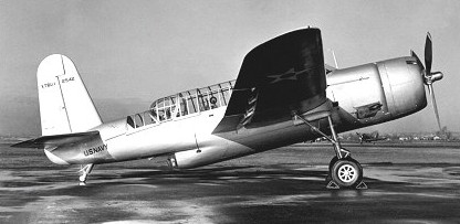
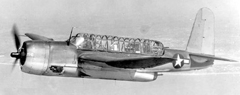
First flying on 22 December 1941 as the Vultee XTBU-1 2542 as a competitor and contemporary to the very similar TBF Avenger, the Sea Wolf was subject to substantial delays.
Vought XTBU-1 2542
A United States Navy torpedo bomber, because of more vital Vought F4U contracts, production of 180 units was assigned by the government to Vultee (Consolidated) in Sep 1943 as the TBY-2.
The type never saw combat; only 180 of the type were built before cancellation.
TBY-2 Engine: 1 x P&W XR-2800-20, 1850hp Wingspan: 17.36 m / 56 ft 11 in Length: 11.96 m / 39 ft 3 in Height: 4.73 m / 15 ft 6 in Useful load: 5743 lb Max. Speed: 492 km/h / 306 mph Cruise: 165 mph Stall: 77 mph Ceiling: 8296 m / 27200 ft Range: 2422 km / 1505 miles Armament: 4 x 12.7mm + 1 x 12.7mm machine-guns, 907kg of bombs Seats: 3
The United States Army Air Corps (USAAC) issued a new specification in 1935. This specification required the development of a new multi-engined, long-range heavy bomber capable of exceeding a top speed of 300 miles per hour, besting a range of 3,000 miles, maintaining a service ceiling of at least 35,000 feet and taking on an internal bombload minimum of 8,000lbs. Production of the Boeing B-17 Flying Fortress was well underway and, in 1938, Consolidated was requested to help in its production. As part of the production initiative, Consolidated executives were brought to Boeing’s plant in Seattle, Washington to visit the factory. It was this meeting that prompted Consolidated to submit their own heavy bomber design with a more modern flair. The USAAC granted Consolidated a design study in January of 1939 under C-212 with the intent that this new aircraft exceed the performance specifications (speed, range and ceiling) of the B-17 and be ready in time for production before the end of the war.
Consolidated wasted no time in developing their design – the Model 32 – and brought about a few revolutionary changes in the approach of American bomber designs. Model 32 sported a tricycle undercarriage – the first American bomber to do so. The monoplane wings were also held in a high shoulder-mounted position, themselves made wide and holding two engines to each wing leading edge in underslung nacelles. The high wings were of less surface area but promoted a higher fuel efficiency standard than the low-mounted assemblies on a B-17. Of note here was Consolidated’s Model 31 (XP4Y Corregidor) foray which utilized the same “Davis” high aspect wing (or “Davis Wing”). This aircraft was of a twin-engine sort and designed as a flying boat. Ultimately, the design fell by the wayside when an order for 200 examples was cancelled by the United States Navy due to program delays and a lack of available Wright engines.
The Davis Wing emerged from the mind of David R. Davis, an aeronautical engineer working on a new wing planform, a planform utilizing a short chord and high aspect ratio along with thickness suitable to fit engines and fuel while maintaining efficiency. His meeting in the summer of 1937 with Consolidated President Reuben H. Fleet allowed the wing design to flourish as one of the most utilized wing planforms of World War 2. The new wing was intended for use on the company’s new flying boat design – the Model 31. Despite the Model 31’s cancellation (only one example emerged from development), the wing was seen as a good step forward in the design of the upcoming B-24 Liberator and became a major Consolidated design mainstay thereafter.
Other features of the Model 32 included the selection of 14-cylinder Pratt & Whitney R-1830 radial piston engines, deep bomb bay fuselage and a twin vertical fin tail assembly. Every Liberator had four Pratt & Whitney R-1830 Twin Wasp 14-cylinder.radial engines. The development process culminated in an offered contract on March 30th, 1939, for a flyable prototype under the designation of XB-24.
The natural finish prototype, Serial 39-680 which had red-white-blue rudder stripes, flew on December 29, 1939, from Lindberg Field in California with 4 x Pratt & Whitney R-1830-33 radial piston engines of 1,000 horsepower each. The prototype was subsequently modified to become the XB-24B, with self-sealing fuel tanks, armour and turbo-superchargers. The latter were placed beneath the nacelles.
Later B-24s had the R-1830-41, -43 or (from 1942) -65, all rated at 1,200 hp and with power at high altitudes maintained by a turbosuper¬charger under the nacelle. Almost all aircraft had 11-ft 7-in Hamilton Standard three-¬blade propellers, without spinners. A basic feature of the air¬craft was large fuel capacity, giving it exceptional range. From the first there were 12 flexible cells between the ribs of the wing centre section, and from 1942 three auxiliary tanks were added in each outer wing. The aircraft failed to reach the projected top speed of the original design intentions but, overall, the first flight was a success. To help iron out the prototype design, a further six YB-24/LB-30A evaluation/pre-production models were ordered, built and delivered. These were followed by the B-24, seven examples of which only one was used for service testing. The B-24 featured de-icing boots and deleted the leading edge slots of previous forms.
Liberators were crewed (depending on the model) by 7 to 10 personnel. The pilot and co-pilot were situated in the high-mounted stepped flight deck with views forward, to the sides and above. The nose gunner, bomber and navigator were housed under a glazed nose well forward in the design. The nose gunner had access to the powered nose turret if the model of Liberator called for one, fitting 2 x 12.7mm machine guns.. Bombardiers and pilots shared a common role for the bombardier would be called on to take flight control of the bomber when engaging in the bombing run via auto-pilot. The navigator could utilise the forward-mounted Plexiglas dome to get his bearings as well as relying on physical landmarks below. If “cheek” machine guns were fitted on a Liberator model, the navigator could man one. The dorsal turret gunner also doubled as the flight engineer and probably maintained the best defensive vantage point, offering an exceptional firing arc when compared to all other available gunner positions. The turret mounted 2 x 12.7mm machine guns. The radioman was situated within the upper portion of the Liberator’s fuselage, positioned just behind the cockpit. Radiomen were required to keep logs of all pertinent actions and could be called upon to man one of the waist guns if needed. The forward flight crew was removed from the rear flight crew, with access between the two sections of the bomber made via a thin scaffold running the length of the two bomb compartments. Entry and exit to the aircraft was through a door positioned towards the rear which made for harrowing emergency exits. Forward crewmen were expected to exit the aircraft by walking across the bomb bay scaffold and make their way to the rear all the while fitted with their parachutes and bulky warming flight suits. The smallest bomber personnel were generally enlisted for operation of the ball turret fitting 2 x 12.7mm heavy machine guns. These fellows wore no parachutes (the small size of the ball turret necessitated this) and made their way inside their turrets after the aircraft was in flight. The ball turret – unlike that on the B-17 – could be retracted into the Liberator’s fuselage during take-off and landing. The ball turret was perhaps the coldest position on a given B-24 with many a crewmember reporting frostbite through those frigid high-altitude sorties.
Waist gunners had single 12.7mm machine guns. These two positions – left and right – were later staggered to compensate for each gunners firing arc. Unlike other turreted positions in the B-24, spent shell casings at these waist positions were not jettisoned from the aircraft automatically, forcing crewmembers to clear their areas themselves. Since firing from these side-perspective positions required a great deal of hand-to-eye coordination via tracer rounds while taking into account target speed and the Liberator’s airspeed itself, waist gunners relied on simple targeting sights in the early years. Only later did they receive assistance in the form of compensating sights to help improve accuracy. The tail gunner was given a powered 2 x 12.7mm machine gun turret.
The B-24 utilized a great deal of hydraulics with such systems spanning nearly every internal inch of the aircraft. Fuel on the B-24 was situated in the wings, just inboard of the inboard set of engines as well as in the upper portion of the bomb bay. As such, any direct hit could easily set the entire aircraft on fire in seconds.
The Army Air Corps ordered seven YB-24s for trials and a further three dozen B-24As for service evaluation. The French ordered 120 B-24As, and even more were purchased by Britain, whose orders embraced a score of Liberators similar to the YB-24.
Production began at Consolidated’s San Diego plant of which the first six were earmarked for the French Air Force as LB-30A models. With the fall of France in 1940, these aircraft made it to British Royal Air Force hands via Lend-Lease. The French Armée de l’Air had ordered 175 Consolidated 32B7. The RAF found their early production forms to be unsuitable for the rigors of combat for they were not even fitted with self-sealing fuel tanks and relegated them to ferry type duties. The USAAC called for 36 of the aircraft while the British ordered 164 for the RAF. Upon reception of the aircraft, the British bestowed the name of “Liberator”, the United States military accepted the British name of Liberator as part of the official designation from then on.
The first of a batch of six Model 32 LB-30s (this latter being the special designation applied to the first British aircraft) first flew on January 17, 1941. These aircraft, AM258-263, were used on the Return Ferry Service between Scotland and Canada from March 1941, and were also operated by BOAC. Since they had been envisaged as bombers they wore the brown-greenblack finish of British machines and had grey serials on their fuselages.
Twenty-six Liberator Is, AM910-929, began to arrive in Britain in the middle of 1941. Five Liberator Is going to BOAC. Some of these were subsequently fitted with a ventral cannon tray in addition to two tail guns and one in each beam position. In such state, and with a full array of ASV aerials on the fuselage top, wings and nose, these aircraft were delivered to No 120 Squadron at Nutt’s Corner to supplement, and later to replace, its Wellingtons. The white Liberators, with their grey and green upper surface camouflage wearing what appeared as a faded or washed-out tone, had grey codes and serials. They were very long-range aircraft able to patrol far out into the Atlantic, and began operations in September 1941. On October 22, AM926: OH-F (OH being aft of the roundel on the starboard side, forward on the port) flown by F1t Lt T. Bulloch, DFC, attacked a U-boat; a year later, AM929: OH-H, flown by Bulloch, sank U-653. By this time many other Liberators were in service.
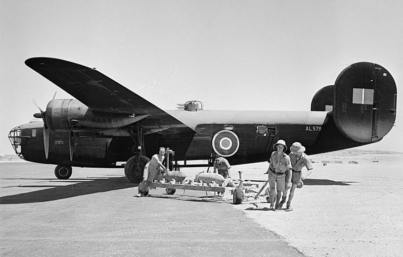
A Liberator II of 159 Squadron in Fayid, Egypt. The LB.30’s Boulton Paul Type A is visible here.
June 1941 saw the initial Liberator deliveries to the USAAC who received nine LB-30s similar to the RAF’s Mk Is, and these were used mainly as transports which undertook some very long flights. Some of these B-24As wore the same colouring as the LB-30s, and one was lost in the Japanese attack on Pearl Harbour in December 1941.
Britain also ordered 165 LB-30s on its own account, and these were built to RAF requirements as Liberator IIs, though only 139 reached Britain (AL503-641), 25 going to the US Army. The Mk II had Boulton Paul four-gun dorsal and tail turrets (These were in addition to a .303 in gun in the nose and two others in the beam positions), a lengthened nose of 2 feet 7 inches, Curtiss propellers, armour, self-sealing tanks and many other changes. Deliveries began to reach the RAF from March 1942. The second aircraft, AL504, was later rebuilt as Winston Churchill’s personal VIP transport, with many features of the later C. IX, including a longer fuselage and tall single fin. To a generally similar standard 38 B-24As were ordered, but only nine were delivered and most were used without armament on the Atlantic ferry service.
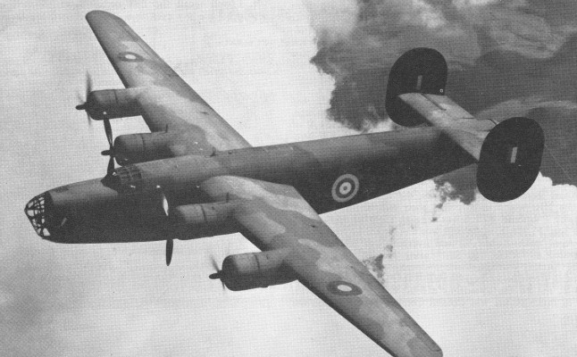
Liberator II
In the main these Liberators, which had the green-black-brown finish, were used by Nos 159, 160, 178 and 511 Squadrons. No 160 formed at Thurleigh near Bedford on January 16, 1942. Operational employment for part of the squadron was first found as a unit of Coastal Command from May 8, 1942, at Nutt’s Corner.
On 4 December 1942 B-24 Liberators of the USAF carried out the first American attack on Italy. Bombs hit ships and port and rail installations in Naples. No enemy fighter planes took to the air. All the bombers returned to base.
Meanwhile the main part of the squadron moved East, and eventually settled at Aqir. Following bomber operations, the unit reformed at Ceylon where it was destined to receive Mk IIIAs and later, the Mk V. No 159 Sqn also formed in England and followed a similar career. It participated in mine-laying, overseas patrols, supply drops and even reconnaissance sorties.
No 178 Sqn spent much time in the Middle East where it formed up at St Jean in Palestine, and later took part in operations in the Western Desert, over. Italy and deep into Eastern Europe. Some of the Mk IIs were used by 511 Sqn as transports, whose forerunner, 1425 F1t, had operated Mk Is. Other IIs entered service with Coastal Command.
Meanwhile American developments of the B-24 were materialising. On the XB-24B the engine cowlings appeared oval in shape, since the oil coolers were now placed on the cowling sides. With R-1830-41 engines of 1,200 horsepower, to absorb the greater power at high altitudes paddle-blade Hamilton Standard propellers were fitted. The XB-24 prototype served as the conversion model, which now gained a top speed increase equal to 37 miles per hour. The XB-24B went on to become the first definitive operational Liberator forms in service with Britain and the United States.
This was a feature of the B-24C, which had a dorsal turret immediately aft of the cockpit, and a Consolidated rear turret to increase the defensive power of the beam guns. Nine of this version were built. It was its successor, the B-24D, which was first to join the American bomber groups. Twenty of the B-24As originally ordered were completed as B-24Ds, but when the total production was completed 2,425 B-24D-CO, 303 B-2413-CF and ten more by Douglas Aircraft had been built. On this, the second most numerous B-24 variant, a very large number of modifications were incorporated, including armament changes and modifications to armour, gun positions and fuel loads.
Nine B-24A models became B-24C models with this engine. B-24C models were essentially A-models but fitted with R-1830-41 series turbo-supercharged engines for increased performance. These engines also featured revised cowlings to differentiate the type further from her origins. Additionally, improvements of the this aircraft fell into the category of defense for a Martin powered turret (2 x 12.7mm machine guns) was installed to the forward portion of the fuselage and an Emerson A-6 powered turret completed the armament in the rear tail gun position.
The B-24D became the first quantitative production run of the Liberator series. These were somewhat similar in nature to the B-24C models before them but fitted improved R-1830-43 supercharged radial piston engines. Improvements to defense were made yet again, with the ventral machine gun position replaced by a remote Bendix-brand belly turret during production. This was still further improved upon with the addition of the Sperry ball turret with 2 x 12.7mm heavy machine guns and a wider firing arc. Late production D-models were given 12.7mm heavy machine guns in their “cheek” positions to protect the forward left and right side angles of the aircraft. 2,381 B-24Ds were made at San Diego, 305 built at Fort Worth and 10 from Douglas at Tulsa. The D had extra tanks in the outer wings and gross weight reached 27,216 kg (60,000 lb).
It was some of the early B-24Ds that the Americans sent to Britain in 1942, when between August and October No 93 Bomb Group settled at Alconbury and on October 9, despatched 24 Liberators (14 of which aborted) with the B-17s that bombed the Fives-Lille factory in Northern France.
During December 1942 the 93rd BG sent a large detachment to North Africa for operations there until March 1943, leaving the 44th BG which had moved to Shipdham, Norfolk, between August and October and commenced operations in November, to continue attacks on the Continent.
The B-24Ds of these units were nearly all despatched to the-Middle East late in July 1943 to participate in more attacks in the Mediterranean area, during the invasion of Sicily and in the disastrous Ploesti low-level raid. The survivors returned to Britain late in August, but small detachments continued to operate in the Middle East. For this reason the Liberator element of the VIIIth Air Force remained small until the winter of 1943-44. By this time later versions of the B-24 were in service.
In the course of production the ventral tunnel gun was replaced by a twin 0.5-in Sperry ball turret, standard on most subsequent bomber versions. The RAF equipped 37 squadrons with the Liberator III (British purchase B-24D) and IIIA (Lend-Lease), these retaining the four 0.303 tail turret, while 977 B-24Ds went to the US Navy as PB4Y-1 long-range ASW aircraft.
The British version of the B-24D was the Liberator III, which was also used by the RAF in two other forms, the Mk IIIA with US equipment and armament, and the Mk V with extensive AW radar fitted in a chin radome and another which replaced the ball turret of the bomber. The standard III had 4 x .303 in guns in her tail turret, a two-gun dorsal turret, one gun in the nose and provision for two beam guns.
Three camouflage schemes were worn by these aircraft. The Coastal Command Liberator III/IIIA/V aircraft had white sides and under-surfaces, with grey and green upper surfaces as applied to the Mk Is. Usually the code letters were grey, but some aircraft had black or red coding. Overseas the maritime reconnaissance Liberators also wore these colours. Such Mk IIIs as were used overseas as bombers retained the olive drab/dark grey finish common to Lend-Lease bombers, and when repainting was undertaken the similar British colourings were applied. A few Liberator IIIs had a green-brown-black finish, and were to be seen in use as transports operating from Britain on the India run after the war.
Some of the IIIs had a Leigh Light fitted.
Apart from their chin radomes, the Mk Vs were similar to the IIIs, which usually had their ball turrets replaced, too, by a radome.
For much of the war Coastal Command relied upon the Mk V, and only during the final year of hostilities did the nose-turreted versions enter service. The Mk III was first used by 120 Sqn during the Summer of 1942, when this was still the only home-based Liberator squadron utilising to the full the long range of the Liberator. By the end of 1943 three Coastal squadrons had IIIs, Nos 120, 86 at Thorney Island and 224 at Beaulieu. During the first half of the year the VLR Mk Vs came into service with Nos 59 and 86 Sqns at Aldergrove, with 53 at Thorney Island, 224 at St Eval, and at Beaulieu where 311 was based. The turn of the year found 120 Sqn mainly using Vs, yet holding on to a handful of the old Mk Is. By mid 1944, when the early Liberator strength was at its peak, Nos 59, 53, 120, 224, 200, 311, 354 and 547 had Mk Vs while Nos 86 and 160 were among those still using IIIs.
In the Autumn of 1943 the US VIIIth Air Force rapidly built up its 2nd Air Division, which was entirely equipped with Liberators and based in East Anglia.
Standard US insignia was now to be seen on the B-24s, the period when the Americans had been flying Liberators with grey stars (except for flight leaders) seemingly over. By the turn of the year, such B-24Ds as were still in use had, in a few instances, shed their camouflage; but those which lived longer in many cases were awarded the most bizarre markings ever carried by operational military aircraft. The intention for the strange colourful was to serve as rallying points for the bombers, as they formed up over Eastern England into their battle formations.
Ford Motor Company produced the B-24E model series, these being fitted with R-1830-65 series radial piston engines. Despite the removal of the ventral machine gun in the improved D-models, these E-models retained them over the Bendix/Sperry ball turrets. Due to the limitations in armament, these Liberators primarily served the United States Army Air Force as pilot, bombardier, gunnery and crew trainers.
The B-24E had Curtiss pro¬pellers, most having the new R-1830-65 engine. This was the first version made at the Ford plant at Willow Run (490), 144 being added by Fort Worth and 167 by Douglas Tulsa.
The XB-24F was a single prototype modified from a B-24D model and used for de-icing testing.
B-24G models were North American Aviation-produced Liberator B-24D version of which 25 examples were built. These Liberators featured the Sperry ball turret and up to 3 x 12.7mm heavy machine guns in the powered nose turret and armour against head-on attacks. The B-24G-1 was a modified G-model form sporting a new Emerson A-6 tail turret. 405 examples of this model were ultimately produced.
Thousands of B-24Ds were likewise com¬pleted with a nose turret, of the same flat-fronted Emerson type as on the G, with a bombardier station in the chin position. These were called B-24H, Fort Worth making 738, Tulsa 582 and Willow Run 1,780. Most of the Tulsa and Willow Run machines had the sloping-front Consolidated hydraulic nose tur¬ret, and either this or the Motor Products A-6B was fitted to the B-24J, which also brought in the C-1 autopilot and M-9 bomb¬sight.
As such, the fuselage was revised with a new bombardier’s compartment to make room for the placement of an Emerson A-6 nose turret. This turret was nothing more than a modified version of the tail turret utilized in previous production examples. A revised tail turret greeted the tail gunner and offered up better views through larger windows. The waist gunners were now positioned in a staggered arrangement to offset their firing arcs and prevent onboard collisions of the two gunners in the heat of combat. The top turret was slightly revised with a higher canopy providing for better visibility for the gunner.
The B-24J was produced in 6,678 examples and were based on the B-24H models sans the defensive armament revisions. Nevertheless, these J-models were given a much-improved autopilot and bombsight system.
The XB-24K was a proposed Liberator derivative by Ford. The idea revolved around fitting the empennage of a Douglas B-23 Dragon twin-engine bomber to the existing airframe of the Liberator. A single prototype was produced as such by converting a B-24D. Though the new aircraft flew with promise – providing for improved handling – such a project during the thick of wartime was deemed much too expensive to undertake and thusly was dropped from serious production consideration. Ford would have handled production of this new B-24N but the order was cancelled on May 31st, 1945. The XB-24K did, however, set the stage for the PB4Y-1 navalized production version of the United States Navy’s Liberator fleet and ultimately led up to the definitive fully-navalized PB4Y-2 “Privateer” model.
The B-24L appeared as a result of the USAAF wanting the weight of the B-24J models reduced. Revisions to this model included the removal of the ventral ball turret and the replacement of the A-6B tail turret with a lightweight M-6A turret or no tail armament at all. The ventral gun turret was replaced by a ring-mounted system sporting 2 x 12.7mm heavy machine guns. 1,667 examples of this model were produced.
The B-24M was another attempt to lighten the B-24.This included the use of a lighter A-6B tail turret and uncovered waist gunner positions. The 2,593 M-models represented the last Liberator production models to see the light of day, with a good number never even being delivered to frontline units and instead scrapped.
The Liberator was evolved into a variety of developmental forms. These included the XB-24N with its single vertical tail fin (would have been produced as the B-24N) and the seven pre-production forms of the N-model in the YB-24N. The XB-24P was a single converted B-24D model used by the Sperry Gyroscope Company to evaluate various in-flight armaments and related systems. The XB-24Q was another single prototype examples, this time produced by General Electric, to showcase radar-controlled turrets. The XC-109/C-109 became a fuel ferry transport in support of Boeing B-24 Superfortress missions over Japan. These Liberators were fitted with special modifications to assist in prevention of onboard explosions of fuel during transport.
The XB-41 was a concept to provide flights of B-24 bombers with similar Liberators armed to the teeth as floating gunship escorts. Though promising on paper, in actual practice the system proved unusable with substantial drops in performance. A single prototype was completed for evaluation and sported no less than 14 x 12.7mm Browning M2 machine guns. Instead of a bombload, the bomb bay was fitted with up to 11,000 rounds of 12.7mm ammunition. Power was derived from 4 x Pratt & Whitney R-1830-43 Twin Wasp radial piston engines of 1,250 horsepower. When evaluated in-flight as escorts alongside the base Liberator bomber, this particular Liberator was unable to keep pace while the aircraft also propagated stability issues and, as such, the proposition for such a machine was ultimately axed in 1943.
The Liberator airframe was utilized for training of various flight crew. These were known by the designations of AT-22 (TB-24), RB-24L, TB-24L and C-87. The RB-24L deserves note here for they were utilized to train Boeing B-29 gunnery crews on remote gun systems as found on the B-24L. The TB-24L was similar to the RB-24L with an increase to radar equipment carried aboard. Base C-87s were used for the training of future Liberator engineers.
The German 200th Bomber Wing, KG200, carried out special transport missions using captured US B-24 Liberator and B-17 Flying Fortress which the Germans called by the code name Dornier Do 200.
The C-87 “Liberator Express” was a 20-passenger transport and appeared in A- (16-passenger VIP transports with R-1830-45 radial engines and sleeping berths), B- (proposed armed passenger transport), and C-models (RY-3 of the USAAF).
C-87
Converted from B-24D, 284 of the C-87 transport version were supplied to the USAF during WW2. Produced in two versions, the C-87 with a crew of five and accommodation for 20 passengers, and the C-87A executive sleeper with 10 berths. The C-87 is powered by four 1200 hp Pratt & Whitney R-1830-43 engines.
Photographic reconnaissance versions of the Liberator were in no short supply. The XF-7 represented the prototype based on the B-24D model. The F-7 was the initial reconnaissance platform developed from the B-24H. The B-24J was the basis of the F-7A while the F-7B was of a similar mold, though sporting up to six cameras in the bomb bay as opposed to the previous type’s three.
The BQ-8 were converted B-24D and B-24J models at the end of their useful operational lives, outfitted to serve as radio-controlled flying bombs.
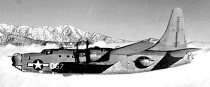
PB4Y-2 Privateer
The PB4Y-2 “Privateer” was a truer “navalized” and dedicated form of the Liberator and based on Ford’s B-24K idea which fitted the tail section of a Douglas B-32 Dragon and its single vertical tail fin for improved stability. The USN made good on 739 examples of this type of which served on even into the Korean War, ultimately retired in 1954.
The US Navy operated the PB4Y-1, which was basically a stock USAAF B 24D with appropriate naval gear added. PB4Y-1 also served to cover all future G-, J-, L- and M-models of the Liberator in USN service. The PB4Y-P became a photographic reconnaissance variant based on the PB4Y-1. However, the USN wanted their own low altitude heavy patrol bomber and contracted with Consolidated in San Diego to produce such a craft. Initially known as the Sea Liberator, the new aircraft was a considerable departure from the B 24. While incorporating the same out¬er wing and landing gear as the B 24, the PB4Y 2 (Consolidated Model 100) featured a fuselage that was lengthened by seven feet and a large single vertical tail. The engines were Pratt & Whitney R 1830 94s without turbosuperchargers and were fitted in new nacelles. XTO bottles could be added to the fuselage and an imposing armament of twelve .50 caliber Browning air cooled machine guns was distributed in an Erco nose turret, two Martin dorsal turrets, two huge Erco side blisters, and a Motor Products tail turret. The first three PR4Y 2s were converted from existing PB4Y-1 airframes and initially retained their distinctive twin vertical tails. The first example flew on 20 September 1943. After initial flight testing, an or¬der was given on 15 October for the delivery of 660 aircraft which had by now been designated as Privateers. This order was followed by another for 770 airframes about one year later. Consolidated began delivering aircraft in March 1944 and production extended to October 1945 but was limited to a total of 740 Privateers by the successful conclusion of the war.
The P5Y was a proposed twin-engine version of the PB4Y-1 but never produced. The C-87 transport version became the RY-1 (C-87A), the RY-2 (C-87 base) and the RY-3 (a dedicated transport alternative of the PB4Y-2 “Privateer”).
The first operational squadrons to receive the type comprised VPB 118 and 119 who took their Privateers overseas beginning in January 1945. The planes began operating out of Tinian, searching for enemy subs, shipping, aircraft, and land targets. By the end of the Pacific War, the Navy was operating 13 Privateer squadrons while five other squadrons flew a mixture of Privateers and PB4Y-1s.
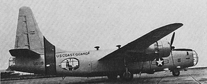
After WW2, the Privateer stayed in front line use and three squadrons (VP 772, VP 871, and VP 28) saw action in the Korean War where, carrying 250 parachute flares apiece, they flew in support of Marine night operations against the enemy. After Korea, Privateers were used for a variety of secondary missions including con¬version to drones and drone directors. The US Coast Guard also used a small number of Privateers modified for search and rescue duties.
P4Y-2G
A few Privateers were also used by foreign nations, the most notable being France, which initially received ten PB4Y 2 aircraft in late 1950 for use against communist insurgents in French Indochina. The aircraft were used as bombers and several were lost in action, but more Privateers were supplied from US stocks and the French eventually received 24 planes. After the French defeat in Indochina, the aircraft saw action in the Algerian war of independence before the last five examples were withdrawn and scrapped in 1961.
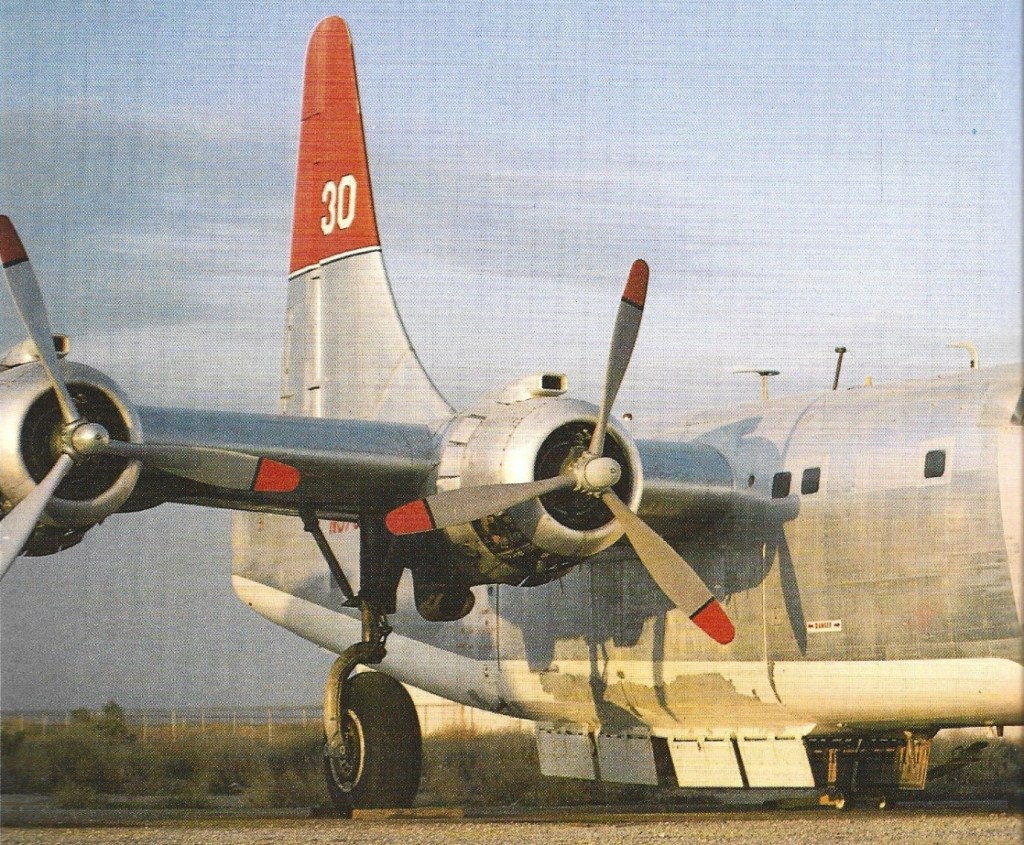
During the late 1950s, surplus Privateers were made available to civilian buyers during sales at Litchfield Park, Arizona. Quite a few aircraft were sold, but the majority were rapidly scrapped or abandoned since they were being purchased for their 94 engines only. At this time, the engines (which were being used for “super” DC 3 civilian transport conversions) were more valuable than the airframes. However, a Restricted Certificate (AR 29) was obtained by Transaire Spraying Co. of Canyon, Texas, to register civilian Privateers as large acreage sprayers and fire bombers.
Whereas many early B-24s and LB-30s were completed or modified as trans¬ports, the desperate need for capable long-range transports in the evacuation of Malaya the Dutch East Indies and related areas forced the urgent development of a properly designed model. This went into production at Fort Worth in April 1942 as the Liberator Express. The main version, with 278 built, was the C-87. This was unarmed (some retained a 0.5-in gun in the tail), but had a large loading door, strong cargo floor and 20 to 25 removable passenger seats. Normal payload with maximum fuel was 4536 kg (10,000 lb), and 24 were sup¬plied to the RAF as the C.VII. The RY-1 and RY-2 were navy conversions, while the C-87A was a VIP version, usually with 16 seats or 10 berths. Five were completed as AT-22 crew trainers, mainly for training flight engineers. A total of 236 B-24Ds was supplied to the RAF, where they were completed as GR.V ASW aircraft for Coastal Command with radar, Leigh light and ASW equipment. Of these, 23 were then converted as C.V transports. In 1943-44 this was the standard model, San Diego building 2,792, Fort Worth 1,558, Tulsa 205, Dallas 536 and Willow Run 1,587. Many were completed as navy PB4Y-ls, with a spherical Erco nose turret and ASW radar instead of the ball turret. The C-109 (208 converted) was a tanker to carry fuel ‘over the hump’ from Burma to China, while 213 (of various models, mainly Js) were converted as F-7 armed reconnaissance aircraft. The RAF received over 1,000 of the H and J models as the B.VI, GR.VJ and C.VI. By April 1944 all new aircraft were unpainted, and fitted with the high-power B-22 turbosupercharger. Shortly afterwards production switched to the B-24L with the tail turret replaced by a much lighter barbette with a wider arc of fire. San Diego built 417 and Willow Run 1,250, some being converted into RB-24L trainers for B-29 gunners with remote sighting stations for B-29-type turrets. The final production bomber was the B-24M, with a lightweight Motor Products tail turret; San Diego built 916 and Willow Run 1,677. There were also numerous experimental models, such as the XB-24P with a radar-equipped gunfire control system, and the XB-24Q used as a testbed for the radar-directed tail turret of the B-47. The XB-24F had the pneumatic deicer boots – which had to be carefully inspected after every mission to make sure there was not even the smallest cut caused by a flak splinter – replaced by a more efficient thermal system, but it remained a one-off. Other one-offs included the XB-41, an early B-24D modified as an escort fighter with seven pairs of 0.5-in guns; a B-24H (built originally as an E) modified with a twin 0.5-in barbette on each side, controlled from a waist sighting station; and a unique B-24 onto which was grafted the complete nose of a B-17G Fortress! As early as 1942 it had been recognised that the B-24 could be redesigned with a single vertical tail which would enhance the poor flight stability and also offer other advantages. On 6 March 1943 a B-24D flew with the tail of a Douglas B-23, and after some refinement this back-end was built on the 42-40234, which began life as a B-24D but had an A-6A front turret. It be¬came the XB-24K, the conversion being done at Willow Run by Ford, who also fitted 1,350-hp R-1830-75 engines. The result was a far better aircraft, perhaps the first Liberator with good flight performance and handling. Convair added longer nacelles housing bigger oil tanks, a new nose and tail with lightweight ball turrets, better cockpit visibility and other changes, and got down to building this as the B-24N. Seven only were completed when B-24 production was stopped on 31 May 1945, 5,168 being cancelled. Independently, in 1943 the US Navy began working with Convair on an optimised ocean patrol and ASW version. This first flew as the prototype XPB4Y-2 Privateer on 20 September 1943, itself a modified B-24 Liberator. This incorporated the extremely tall single fin already developed for the Navy RY-3 transport, all 40 of which were supplied to the RAF as Liberator C.IX transports (as noted, the much earlier VIP aircraft AL504 Commando, was modified close to C. IX standard). Apart from the new tail the PB4Y-2 intro¬duced a completely revised fuselage, further stretched to 22.73m (74 ft 7 in), 1,350-hp R-1830-94 engines without turbos, resulting in the cowlings being elliptical vertically instead of horizontally, and defensive armament of six pairs of 0.5-in guns (nose, forward dorsal, aft dorsal, left and right waist and tail). Fuel capacity was enhanced and the normal crew was increased to 11, with extensive radar, ASW and electronic-warfare equipment. There was provision for 3628 kg (8,000 lb) of bombs, torpedoes, mines, depth charges or other stores, and underwing pylons could be fitted for the ASM-N-2 Bat anti-ship cruise missile which saw much action in 1945. Three prototype PB4Y-2’s were ordered and flown, all based on the preceding PB4Y-1 Navy models, designed specifically for anti-submarine warfare.
PB4Y-2 Privateer
The Privateer operated well into the years encompassing the Korean War, serving in some capacity as Elint (electronic intelligence) models. A single Privateer was also the first casualty of the Cold War, being engaged and shot down by Soviet forces. Some Privateers were utilized in the maritime patrol mission as well. In all, it was an economical stop-gap design that served well for a number of years – too late for much use in World War 2, but serving an effective role in the post-war years nonetheless. The total production count was well over 1,300 examples by the end of its production run. A total of 18,430 Liberators having been built. Unlike the B-24 the Privateer remained in service after the war, being redesignated P4Y-2 in 1952. There were several post-war versions, including the P4Y-2G for the Coast Guard, with no armament and considerable modification, and the special ‘ferret’ electronic-warfare versions which, together with similarly equipped Martin P4M Mercators, carried out the Navy’s Elint (electronic intelligence) missions during the post-war years. One PB4Y, operating from Wiesbaden over the Baltic on 8 April 1950, was shot down by a MiG-15, all 10 crew being killed. The Privateer also got to drop bombs in anger. Serving with Flottilles 8F/28F of the Aéronavale, the type was used in the bomber role throughout the French Colonial War in Indo-China.
740 P4Y-2’s were built for the U.S. Navy and several remained in service in 1955 for overseas reconnaissance P4Y-2S), as motherplanes for Bat guided missiles (PB4Y-2B), and as target drones (PBY-2K). All had four 1350 hp Pratt & Whitney R-1830-94 engines.
British Liberators
Early British Liberators were the LB-30A and LB-30B models of which very few were constructed and delivered, these via Lend-Lease. LB-30A’s were originally intended for French use and fell into British hands in six examples with the fall of France. The Liberator B.Mk I’s (LB-30B) were B-24A’s of which 20 were delivered to the Royal Air Force. These were eventual initial disappointments for the RAF which saw fit to give them new life as Liberator GR.1s used in anti-submarine sorties.
The Liberator B.Mk II was next and were closest in nature to B-24C models. These Liberators had their fuselages extended by three feet with a revised deeper fuselage and expanded tail plane unit. 165 examples of these Liberators were produced and became the first “combat-worthy” British Liberators. British Prime Minister Winston Churchill used a refurbished Liberator II as his personal transport.
The Liberator B.Mk III were based on B-24D models fitting appropriate British-requested internal systems. Defense was handled by a single machine gun in the nose (.303 caliber), a twin-gun dorsal turret, two waist gun positions and a 4 x machine gun battery located in an Avro Lancaster-type tail turret. At least 156 of the type were delivered. The Liberator B.Mk IIIAs were nothing more than B-24D models retaining their American-based equipment and armament.
The Liberator B.Mk V were D-models revised to carry more fuel with less armor while retaining the defensive armament capabilities of the Liberator B.Mk III models. The Liberator B.Mk VI were B-24H models with the defensive armament of H-models but Boulton Paul tail turrets. B-24J models were represented as Liberator B.Mk VIIIs.
RAF Coastal Command modified several B-24D models for the anti-submarine role complete with the Leigh Light 22-million candela search light (carried underwing), search radar and air-to-surface rockets. Coastal Command also made use of the Liberator GR.Mk VI (B-24G/H/J models) as long-range reconnaissance forms and B-24J models under the Liberator GR.Mk VIII designation for the anti-submarine role.
The Liberator C.Mk IV were B.Mk VIII models modified to serve as transports while Liberator C.Mk VII was the designation used to cover C-87s. Liberator C.Mk VIII models were nothing more than G.Mk VIII modified to be used as transports.
The Royal Air Force designated their RY-3/C-87Cs as Liberator C.Mk IX. The B-24 was officially retired as soon as the war ended – this occurring in 1945. A single Liberator unit cost American taxpayers between $297,627 and $336,000 US at the time of her production. Production years ranged from 1940 until 1945. Although often overshadowed by the B17 Flying Fortress, the B24 Liberator was built in greater numbers than any other US military aircraft 18500 aircraft being built by Consolidated, Douglas, North American and Ford between 1940 and 1945. 1900 B24s were supplied to the Royal Air Force. Liberators were used by RAF bomber squadrons in the Middle East, and from January 1944 became the principle RAF strategic bomber in the Far East. Liberators were also deployed by RAF Coastal Command, playing a key role in the war against Germany’s submarine fleet. Liberators also saw service as transports; AL504 Commando became the personal aircraft of Prime Minister Winston Churchill for a short time. Liberators continued in use until December 1968 when the Indian Air Force retired its former RAF machines. Six from the first batch for the UK were directed to British Overseas Airways Corporation (BOAC) for use in the North Atlantic Return Ferry Service. During WWII, Captain D.C.T. Bennett known as Pathfinder Bennett, flew the first crossing on 14 May 1941 taking 14½ hours. The thousandth crossing of the Atlantic took place in September 1944.
The C-87 Liberator Express was a transport version of the B-24D bomber. The first Liberator transport was created by converting B-24D serial number 42-40355 which had been damaged in a crash landing in the Arizona desert in early 1942. All of the bombing equipment and defensive armament were deleted, and the nose glazing where the bombardier sat was replaced by a sheet metal nose which hinged to the right. A floor was installed through the bomb bay and into the waist compartment. Rectangular windows were cut into the sides of the fuselage, and 25 seats were added. There was a large 6×6 door incorporated into the port side of the fuselage. The navigator’s compartment was relocated to a position just aft of the pilot’s cockpit, and an astrodome was installed where the top turret had been located. The tail turret was removed and replaced by a metal fairing. The crew was normally four–pilot, copilot, navigator, and radio operator. The prototype was flown to Bolling Field in Washington, DC for evaluation. The Army was sufficiently impressed that they ordered the aircraft into production as the C-87 Liberator Express. All of the C-87s were built at Consolidated/Fort Worth and were delivered between September 2, 1942 and August 10, 1944. The first 73 C-87s were conversions from existing B-24Ds, with the remainder being built from scratch on the Fort Worth production line as transports. A total of 287 C-87s were built by Consolidated/Fort Worth. The C-87s were not assigned production block numbers, but there were six different versions of the C-87 that were built which incorporated a number of specific changes. Most C-87s were assigned to Air Transport Command. When Burma fell to the Japanese in April of 1942, China’s only route to the Allied supply line, the Burma Road, was cut. The only route to China from India was now by air, involving a treacherous flight over the Himalayas, the highest mountain range in the world. This route came to be known as the Hump. On September 12, 1943, the Air Transport Command established a new route to China via the Hump. This route began at Patterson Field, Ohio and ended in China. This round trip route covered 28,000 miles and took twelve days to complete. ATC C-87s became an important part of this operation. So dangerous was this route that the USAAF ended up losing three crewmen for each thousand tons of cargo that reached China. The Hump operation ended up costing the lives of over a thousand USAAF crewmen. During the war, so great was the need for an air transportation system that the Army was forced to turn to the commercial airlines to help operate the system. In addition to ATC, four commercial airlines operated the Liberators under contract. These were Consairways, American Airlines, United Air Lines, and T&WA. Consairways was organized as a separate subsidiary of Consolidated Aircraft. The original purpose of Consairways was to return the crews ferrying aircraft to the Pacific back to the USA, but it later ended up flying cargo of just about every imaginable type back and forth between the USA and the Pacific theatre. It also flew USO shows to entertain the troops in the Pacific. Consairways operated a mixture of LB-30s, C-87s, and B-24s. Two C-87s known to have been operated by Consairways were 41-24029 and 41-11706. In January of 1943, American Airlines was awarded a contract by ATC to operate C-87s over North Atlantic and South Atlantic routes. These planes flew in military insignia and markings and carried USAAF serials, but were operated by civilian crews. Later, American Airlines personnel also flew numerous dangerous Hump missions. C-87s flown by American Airlines: 41-11608, 41-11639, 41-11657, 41-11674, 41-11675, 41-11729, 41-11731, 41-11744, 41-11745, 41-11746, 41-11788, 41-23695, 41-23859, 41-23792, 41-23959, 41-24141, 41-24163, 42-107274, 43-30565. One of the more notable exploits of AA-piloted C-87s was the 31,000-mile trip made by FDR’s “One World Ambassador”, Wendell Wilkie, aboard C-87 41-11608 Gulliver. This involved a 51-day mission to Cairo, Palestine, Baghdad, Teheran, Moscow, and China, and then a return to the United States via a route across the Pacific. AA later traded in their C-87s for more advanced C-54 Skymasters. United Airlines was awarded a contract by ATC to fly trans-Pacific routes and to fly intra-theater leave shuttles ferrying armed forces personnel back and forth between the front and leave ports in Australia and New Zealand. C-87s operated by United Airlines included 41-24005, 41-24027, 41-24028, 41-24160, 41-24252, 41-24253, 41-11608, 41-11640, 41-11642, 41-11642, 41-11655, 41-11656, 41-11789, and 41-11861. During the war, Transcontinental & Western Airlines (T&WA) – later to become Trans World Airlines or TWA – operated Liberators for training and in support of USAAF Ferry Command operations. In late 1942, T&WA’s new Intercontinental Division was assigned three C-87s to fly the South Atlantic route between the USA and the Middle East. The C-87A was a VIP transport version of the basic C-87. The C-87 had been essentially a “no-frills” transport, with little attention being paid to passenger comfort. The C-87A was designed for more passenger comfort, and had only 16 seats. It could be fitted with Pullman-type upholstered seats that could be converted into five berths. Because of the different seating accommodation, the window arrangement was different. The first three C-87As were named Gulliver I, Gulliver II, and Gulliver III. A total of six were built, three for the USAAF and three for the US Navy. C-87A 41-24159 later became the first “Air Force One” for President Franklin Roosevelt, and was renamed Guess Where II.
Three C-87A VIP transports were turned over to the Navy under the designation RY-1. Navy BuNos were 67797/67799. Five C-87s were transferred to the US Navy under the designation RY-2. BuNos were 39013/39017.
Five C-87s were converted into AT-22 trainers, which were employed for training flight engineers. Their serial numbers were 42-107266, 43-30549, 43-30561, 42-30574, and 43-30584. Six stations were provided in the fuselage for the instruction of flight engineers in the operation of powerplants. They were intended to train engineers that were going to be flying aboard B-24 and B-32 bombers In 1944, these five planes were redesignated TB-24D.
24 USAAF C-87s were transferred to the RAF under Lend-Lease for use by Transport Command as Liberator C.VII. Their RAF serials were EW611/EW634. Known USAAF serial numbers are 44-39219 and 44-39248/39261, which accounts for only 15 of the 24 C.VIIs. They were used by Nos. 232, 246, and 511 Squadrons starting with mid to late 1944 up until the end of the war. EW611, ex-USAAAF 44-39219, became G-AKAG. The RAF did not keep its Liberator C.VIIs very long, disposing of the last examples in 1946.
The C-87s were not very popular with their crews, who complained about all sorts of hazards, particularly with the fuel system, with the engines, and with the cockpit accessories. The C-87 was notorious for problems with leaking fuel tanks, and midair fires were an ever-present danger. The C-87 also had some dangerous icing properties, which made it a very risky plane to fly over the Hump. There were few tears shed when the Army’s C-87s were withdrawn from service and replaced by more reliable Douglas C-54 Skymasters.
The PB4Y was first used in the fire-bomber role in 1959. It could carry 2000 USG, and dump it on a fire all at once.
XB-24 Engines: 4 x Pratt & Whitney R-1830-33 Twin Wasp, 1100 hp. Prop: 11 ft 7 in Hamilton Standard 3 blade. Aspect ratio: 11.5-1. Bomb cap: 8000 lb. Armament: six 0.3-in mg.
XB-24B Engines: 4 x Pratt & Whitney R-1830-41.
B-24C Engines: 4 x Pratt & Whitney R-1830-41.
B-24D / Liberator III Engines: 4 x Pratt & Whitney R-1830-43. Gross wt: 27,216 kg (60,000 lb). Armament: 2 x 12.7mm machine guns in nose turret 2 x 12.7mm machine guns in tail turret 2 x 12.7mm machine guns in dorsal turret 2 x 12.7mm machine guns in ventral ball turret 1 x 12.7mm machine gun in left-waist fuselage position. 1 x 12.7mm machine gun in right-waist fuselage position. Up to 8,800lbs of internal ordnance.
B-24E Engines: 4 x Pratt & Whitney R-1830-65 Prop: Curtiss.
B 24G Liberator Nose turret
B 24H Liberator Engine: 4 x Pratt & Whitney R 1830-65 Twin Wasp, 1200 hp/895 kW Length: 67.159 ft / 20.47 m Height: 18.012 ft / 5.49 m Wingspan: 110.007 ft / 33.53 m Wing area: 1047.983 sq.ft / 97.36 sq.m Max take off weight: 71200 lb / 32296.0 kg Weight empty: 36,500 lb / 16556.0 kg Max. speed: 252 kts / 467 km/h / 290 mph at 25,000ft/7620m Cruising speed: 187 kts / 346 km/h Service ceiling: 28000 ft / 8535 m Climb to 20,000 ft / 6095m: 25 min 0 sec Wing loading: 68.06 lb/sq.ft / 332.0 kg/sq.m Range: 1825 nm / 3380 km Crew: 12 Armament: 10x cal.50 MG (12,7mm), 2268kg-5806kg Bomb.
Liberator VI/VII B-24H with improved bombsight & autopilot
B-24J Liberator Engines: 4 x Pratt & Whitney R-1830-43, 1,200 hp Takeoff power: 1200 BHP @ 49″ Hg/2700 RPM Emergency power: 1350 BHP @ 53″ Hg/2700 RPM Max climb power: 1100 BHP @ 46″ Hg/2550 RPM Normal climb power: 990 BHP/39″ Hg/2550 RPM Max cruise power: 820 BHP/35″ Hg/2325 RPM (Auto Rich) Normal cruise power: 610 HP/30″ Hg/2000 RPM (Auto Lean) Length: 67.16ft (20.47m) Width: 110.01ft (33.53m) Height: 18.01ft (5.49m) Empty Weight: 36,500lbs (16,556kg) Maximum Take-Off Weight: 65,001lbs (29,484kg) Ramp Weight (equipped with oil and crew): 39,175 lb Fuel capacity: 3,576 USG with bomb bay tanks Vmax: 275 mph IAS Top Speed @ Alt: 295 mph TAS @ 25,000 ft, 50,000 lbs. aircraft weight Cruise @5,000ft: 158 mph IAS/169 mph TAS @ 31″ Hg/1650 rpm (60,000 lb) Cruise @25,000ft: 150 mph IAS/222 mph TAS @ 31″ Hg/2100 rpm (60,000 lb) Maximum Range: 2,001miles (3,220km) Rate-of-Climb: 800ft/min (244m/min) Climb: 25.5 minutes to 20,000 ft (60,000 lbs.) Climb: 43 minutes to 30,000 ft (60,000 lbs.) Fuel to climb (25,000 feet): 240 gallons Distance to climb (25,000 feet): 140 miles Service Ceiling: 28,002ft (8,535m; 5.3miles) Takeoff distance to 50 ft: 4,250 ft (60,000 lb) 1 g stall speed, clean: 123 mph IAS (56,000 lb) 1 g stall speed, landing: 101 mph IAS (56,000 lb) Accommodation: 7 to 10
XB-24K Engines: 4 x R-1830-75, 1,350-hp.
GR.Mk.VI Engines: 4 x Pratt & Whitney R-1830-43 or -65, 1200 hp. Bomb load: 12,800 lb. Range: 900-2290 mile.
B-24L B-24J with manually operated tail gun
B-24M Revised B-24J
Consolidated PB4Y-2 Privateer Engines: 4 x Pratt & Whitney R-1830-94 Twin Wasp 14-cylinder radial, 1350 hp Length: 74 ft 7 in (22.73m) Wingspan: 110 ft 0 in (33.53m) Wing area: 97.36 sq.m / 1047.97 sq ft Wing load: 62.12 lb/sq.ft / 303.0 kg/sq.m Height: 30 ft 1 in (9.17m) Empty weight: 17018 kg / 37518 lb Maximum Take-Off Weight: 65,003lbs (29,485kg) Maximum Speed: 287mph (462kmh; 249kts) Cruise speed: 225 km/h / 140 mph Maximum Range: 2,796miles (4,500km) Service Ceiling: 20,669ft (6,300m) Armament: 2 x 12.7mm machine guns in forward dorsal turret 2 x 12.7mm machine guns in rearward dorsal turret 2 x 12.7mm machine guns in nose turret 2 x 12.7mm machine guns in tail turret 2 x 12.7mm machine guns in left waist blister position 2 x 12.7mm machine guns in right waist blister position Up to 12,800lbs of internal stores. Accommodation: 11
P4Y-2G Privateer Engines: 4 x Pratt & Whitney R-1830-94, 1350 hp Wingspan: 110 ft Length: 74 ft 7 in Empty weight: 37,485 lb Loaded weight: 65,000 lb Max speed: 237 mph at 13,750 ft Econ cruise: 140 mph ROC: 1090 fpm Range: 2800 mi
Consolidated C-87 Liberator Express: Engines: 4 x Pratt & Whitney R-1830-43 radial, 1200 hp at 2700 rpm for takeoff. Maximum speed 300 mph at 25,000 feet. Climb to 20,000 ft: 60 minutes. Service ceiling 28,000 feet at 56,000 pound takeoff weight. Normal range at 60% power: 1400 miles at 215 mph at 10,000 feet. Maximum range: 3300 miles at 188 mph at 10,000 feet. Empty weight: 30,645 lb Normal loaded weight: 56,000 lb Wingspan 110 feet 0 inches Length 66 feet 4 inches Height 17 feet 11 inches Wing area 1048 square feet. Fuel: 2910 US gallons. Accommodation: Crew four (pilot, copilot, navigator, radio operator). Passengers capacity: Up to 25 Range 10,000 lb load: 1000 miles Trans-oceanic cargo capacity: 6000 lb
C-87 Engines: four 1200 hp Pratt & Whitney R-1830-43 Wingspan: 110 ft Length: 66 ft 4 in Empty weight: 30,645 lb Loaded weight: 56,000 lb Max speed: 306 mph Normal range: 1400 mi Max range: 3300 mi Crew: 5 Accommodation: 20 passengers
C-87A Engines: four 1200 hp Pratt & Whitney R-1830-43 Wingspan: 110 ft Length: 66 ft 4 in Empty weight: 30,645 lb Loaded weight: 56,000 lb Max speed: 306 mph Normal range: 1400 mi Max range: 3300 mi Accommodation: 10 berths
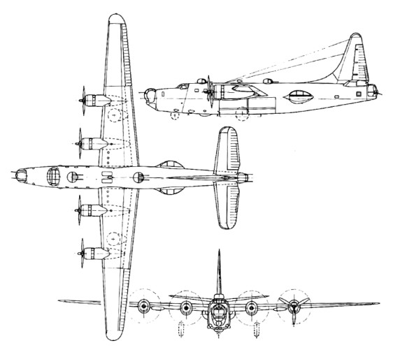
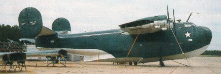
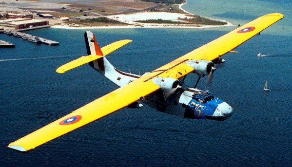
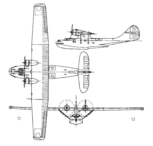
The Consolidated PB2Y Coronado series was a planned replacement for the 1930’s era Consolidated PBY Catalina design already in place.
The PB2Y Coronado first appeared in the XPB2Y-1 prototype form, was first flown in December 1937, and delivered to the US Navy in August 1938. After service trials it served for some time as Flagship of Aircraft, Scouting Force, US Navy. It suffered almost immediately with poor water-based handling and equally dangerous in-air instability issues related largely to the single fin tail design. The tail section was redesigned to incorporate twin-rounded vertical fins which helped iron out the handling issues. The US Navy took this redesigned model as the PB2Y-2 and continued testing as needed. Results necessitated the addition of better armor protection and self sealing fuel tanks which further produced the PB2Y-3. This model would go on to become the definitive production model and also join service in limited numbers with the British RAF.
The first PB2Y-2 (the production development) went into service in January 1941. The PB2Y-3 was ordered in quantity in 1941 and remained in production until 1944 as a long-range patrol-bomber flying-boat.
The large ASV radome was visible just aft of the cockpit. Wings were high mounted and forward on the tall fuselage and featured retractable wing-tip floats which helped in building better aerodynamic tendencies (this function was similar to the PBY Catalina). The twin fin tail section was also mounted high on the design at rear.
Armament of the Coronado was twin 12.7mm (.50 caliber) M2 machine guns housed in a bow turret, a dorsal turret amidships and a rear turret just aft and between the twin tail fins. An additional 12.7mm machine gun was positioned to fire from hatches in the beam position on either side. The Coronado could fulfill an offensive role by being fitted with up to 1,000 pounds of bombs (held internally in the wing roots) or two Mark 13 type torpedoes held externally.
Despite being of sound design, the Coronado did not dislodge the PBY Catalinas in long distance reconnoitering sorties. Additionally, the Coronado was not implemented greatly as a bomber or anti-ship element, being superseded in this role by the equally capable Consolidated PB4Y-1 series, and aircraft similar in scope but dedicated to land bases and thus not needing any specialist training for water operations.
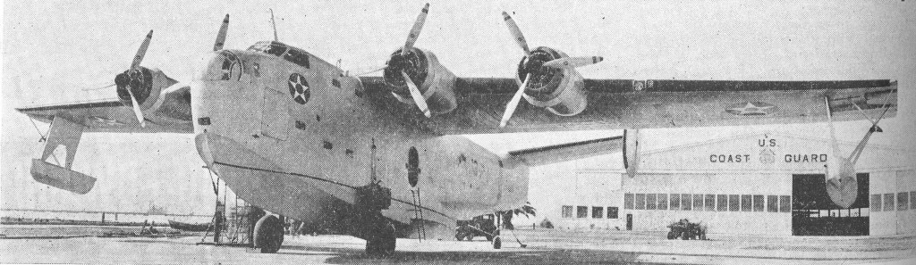
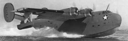
Many Coronado flying-boats were converted into transports under the designation PB2Y-3R, with military equipment removed, nose and tail turret positions faired over and the four 894kW Pratt & Whitney R-1830-88 Twin Wasp engines replaced by R-1830-92. Accommodation in this version was for a crew of five (instead of ten) and 44 passengers; 7,257kg of cargo; or 24 passengers and 3,900kg of cargo. A naval ambulance version of the Coronado was also produced as the PB2Y-5H, accommodating 25 stretchers.
In British service, the PB4Y Coronado was known as the Coronado Mk I, of which some 10 PB2Y-3 models were acquired by RAF Transport Command for transatlantic freight carrying. Several subvariants appeared as the PB2Y-3R – a dedicated transport seating some 45 passengers or cargo – and the PB2Y-5R – a converted model for air ambulance duties with room for 25 litters.
PB2Y-3R at San Diego Bay 1944
In all, 210 Coronados were produced with most models serving in the Pacific Theater (sans the RAF models in the Atlantic).
Consolidated PB2Y Coronado Long range flying boat bomber, USA, 1937 Engine : 4 x Pratt&Whitney R 1830-88 Twin Wasp, 1184 hp Sizes and weights Length : 79.265 ft / 24.16 m Height : 27.493 ft / 8.38 m Wingspan : 114.993 ft / 35.05 m Wing area : 1779.935 sqft / 165.360 sq.m Max take off weight : 68011.0 lb / 30844.0 kg Weight empty : 40942.4 lb / 18568.0 kg Max. speed : 194 kts / 359 km/h Cruising speed : 123 kts / 227 km/h Service ceiling : 20505 ft / 6250 m Cruising altitude : 1509 ft / 460 m Wing load : 38.34 lb/sq.ft / 187.00 kg/sq.m Maximum range : 2059 nm / 3814 km Range : 1191 nm / 2205 km Armament : 8x cal.50 MG (12,7mm), 5443kg Bomb.
Consolidated PB2Y-3 Coronado Engines: 4 x Pratt & Whitney R-1830-88 Twin Wasp 14-cylinder air-cooled radial, 1,200hp, 895kW Length: 79 ft 3 in (24.2m) Wingspan: 114.99ft (35.05m) Wing area: 165.36 sq.m / 1779.92 sq ft Height: 27 ft 6 in (8.38m) Empty Weight: 40,935lbs (18,568kg) Maximum Take-Off Weight: 68,002lbs (30,845kg) Maximum Speed: 223mph (359kmh; 194kts) Cruise speed: 227 km/h / 141 mph Maximum Range: 2,371miles (3,815km) Rate-of-Climb: 570ft/min (174m/min) Service Ceiling: 20,505ft (6,250m; 3.9miles) Armament: 2 x 12.7mm machine guns in bow turret 2 x 12.7mm machine guns in dorsal turret 2 x 12.7mm machine guns in tail turret 1 x 12.7mm machine gun in left beam position 1 x 12.7mm machine gun in right beam position 8 x 1,000lb (454kg) bombs held internally in wings OR 2 x Mark 13 torpedoes (externally held) Accommodation: 10 + 45 Hardpoints: 2
The Consolidated Model 28, designed by Isaac Laddon, originated from a US Navy requirement of late 1933.
The prototype XP3Y-1, developed from the PY-1/P2Y and flown for the first time on 28 March 1935, introduced the parasol wing constructed on the basis of a cantilever wing requiring no supporting structures, although two small-section struts were mounted between wing and hull on each side. Another new feature was the introduction of stabilising floats which retracted in flight to form the wingtips. Power was from two 825 hp R-1830-54 engines.
Initial trials of the prototype left little doubt that the Navy was about to acquire a significant aircraft. Sixty PBY-1 ordered in 1933 and powered by 850 hp engines were ordered and began to enter squadron service in 1937. By mid-1938 14 squadrons were operational.
The first 22 aircraft built were PBYs and were built in the USA. Also built by Boeing Aircraft of Canada at their Vancouver plant, as the PB2B-1. Fifty-five Boeing Canada-built PBY-5 were eligible for conversion to 28-5ACF status which allows further conversion to air transport category.
Production as a pure flying-boat ended with the PBY-4, for the last of these was converted to an amphibian with retractable tricycle-type landing gear, under the designation XPBY-5A. Subsequent aircraft had this as standard. Production of the PBY series would be undertaken by Consolidated in the United States, Canadian Vickers and Boeing of Canada in Canada, the Naval Aircraft Factory in Britain and state factories in the Soviet Union under the Lend-Lease Act. Between 27 and forty Model 28 Catalinas were built in the Soviet Union as the MP-7.
On 7 May 1945, RAF Coastal Command flew its last raid against a German submarine when a Catalina of 210 Sqn, piloted by Lt. K. Murray, located a U-boat that had stopped dead between Shetland Islands and Norway, and recorded engine noises showing that the U-boat must be in distress. The Catalina dropped a series of depth charges. The boat was U-230 under 1st Lt. Emmerich, and it radioed later that it was badly damaged. On Wednesday 9 May 1945, the U-230 went down with all her crew off Bergen, Norway.
Initial export aircraft went to Russia, where the type was built subsequently in large numbers under the designation GST. The RAF acquired a single example for evaluation in 1939 and almost immediately ordered a batch of 50, the first of many to serve with Coastal Command. The name Catalina (adopted first by the RAF) was used later by the USN for the various versions which entered service. The type was also to serve with the RAAF, RCAF, RNZAF and the air arm of the Dutch East Indies.
The RNZAF operated 56 Catalinas, both PBY 5 and PB2B 1 models. They were used for maritime reconnaissance and air sea rescue between 1943 and 1956. The PBYs were withdrawn from service post war and sold for scrap in 1952; the PB2Bs soldiered on until replaced by Short Sunderlands in 1953 54.
The RCAF chose the PBY-5A as its replacement for the Supermarine Stranraer. During World War II, Boeing Aircraft of Canada, Canadian Vickers and Canadair Ltd. made almost 800 PBY’s. The RCAF called its version the ‘Canso A’ – A for amphibious. The PBY-5A first flew for the Royal Canadian Air Force on 20 March 1944.
Canadian Vickers built 130 for the RCAF, 9806-9844, and 11001-11100, and 230 to the USAF as OA-10A, 44-33868 to 44-34097.
139 were exports to the RAF, 36 as Catalina IIA, 12 PBY-5A as Catalina III, 11 PBY-5A as Catalina IV, and 70 PBY-5B as Catalina IVA.
A number were operated by the USAAF as OA-10As. Seventy-five went to the USAAF as OA-10B in 1945.
Israeli Air Force PBY-5A Catalina
The Amtorg KM-2 was an improved PBY Catalina, built under Consolidated license.
The GST (Russian State Aircraft Factory) was responsible for the production for a licence-built version. Russian-built engines were substituted and armament consisted of three 12.7mm or 7.62mm machine guns.
Russian State Aircraft Factory PBY
Altogether 2398 were built by Convair, 676 in Canada, and others in Russia.
Steward-Davis built about 13 Super Catalina civil conversion of PBY-5A/-6A wth two 1900hp Wright R-2600, larger squared tail, prop spinners, and faired-over nose turret. Many served in USFS fire duty, notably N6453C and N9505C.
In 1964 the province of Quebec, Canada, was using seven modified PBY to reduce forest fires. Field Aviation of Toronto modified the PBY to carry 800 USG of water that could be dumped in 0.8 sec and refilled in 14 sec during a touch and go on lakes or rivers.
Gallaudet Airplane Corp was dissolved 1923 and factory acquired by Consolidated Aircraft Corporation with Reuben H.Fleet. Original factory was quickly outgrown by the company formed May 29,1923 and moved to Buffalo, NY, in 1924, leasing part of a wartime Curtiss factory. In the 1920s and 1930s produced small numbers of civil types, but main output was military and between 1924-1932 included more than 770 PT-1 /311 and NY primary training biplanes for the USAAC and Navy, plus a small batch of similar 0- 17s for observation duties. The creation of the civil Model 14 “Husky”trainer led to the creation of the Fleet Aircraft Division in 1929. Thomas Morse Aircraft acquired 1929. In the 1930s Consolidated specialized in marine aircraft, P2Y twin-engined patrol flying-boats being built 1931-1933; followed by P-30 single-seat fighter monoplanes for the Army in 1933-1935. In autumn 1935 company moved to San Diego, California, gaining a harbor for testing its maritime designs, which continued with the P3Y/PBY Catalina family. During a ten-year production life 2,400 Catalinas were built by Consolidated and hundreds more by other companies. Production of PB2Y Coronados began in 1939. In 1940 Hall Aluminium Co acquired. Company began a five-year program of building more than 11,000 B-24/C- 87/PB4Y/RY Liberator and Privateer bomber, transport, and patrol aircraft for the U.S. Services and the RAF. Liberator production was also undertaken by Ford, Douglas, and North American. Final wartime product was the TBY Sea Wolf. A 34 percent controlling interest in Consolidated acquired December 1941 by Vultee Aircraft Inc., and management links from then led to merger of the two companies on March 17,1943 as Consolidated Vultee Aircraft Corporation. Amalgamation from March 17,1943 of Consolidated Aircraft Corporation and Vultee Aircraft Inc., whose wartime production programs are listed under these separate headings. By the end of Second World War Consolidated Vultee was largest aircraft manufacturing organization in the U.S.A., with factories at San Diego and Vultee Field, California; Fort Worth, Texas; Nashville, Tennessee; Wayne, Michigan; New Orleans, Louisiana; Miami, Florida; and Allentown, Pennsylvania; plus modification centers at Tucson, Arizona; Elizabeth City, North Carolina; and Louisville, Kentucky. Late-war/early post-war programs included B-32 Dominator long-range bomber, L-13 liaison/observation aircraft and multi-engined B-36 intercontinental bomber. The company entered the commercial field with first flight, in summer 1946, of twin-engined Model 110, from which later stemmed well-known 240/340/440 Metropolitan series of medium-sized shorthaul airliners. Various noteworthy military prototypes included the XB-46 jet bomber, XP-81 single-seat mixed-power escort fighter, XF-92 rocket-powered interceptor, XA-41 close-support aircraft, and XF2Y Sea Dart hydro-ski fighter. A small number of R3Y Tradewind four-engined transport flying-boats Were built for the U.S. Navy. In the early 1950s Consolidated Vultee began calling its products “Convair” types, and on April 30,1954 it became the Convair Division of General Dynamics Corporation, which was then the major shareholder.
USA Formed in Kansas City October 1942, after the acquisition of Rearwin Aircraft & Engines Inc. by New York interests. In 1943 it received substantial orders for Waco CG-3A and -4A troop-carrying gliders for the USAAF. It obtained manufacturing rights in 1945 for the Trimmer three-seat twin-engined light amphibian (prototype only), formerly built by Allied Aviation. In 1946 Commonwealth Aircraft Inc. began producing Model 185, a development of the prewar Rearwin Model 175. Early that year the company took over the Columbia Aircraft Corporation, all manufacturing being transferred to the letter’s Valley Stream factory. In March 1946 it acquired a non-aircraft company at Port Washington as a manufacturing base for the Trimmer, which did not go into series production. The Skyranger model was built in small numbers in 1946-1948. As the anticipated post-war boom in civil aviation had not started, Commonwealth went bankrupt in 1947.
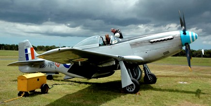
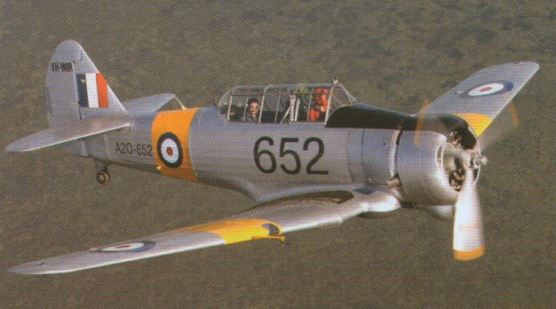
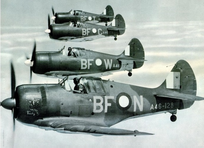
In 1943, the Australian government arranged for the Commonwealth Aircraft Corporation (CAC) to manufacture the Mustang Mk IV (P-51D) under licence from North American Aviation. The RAAF urgently needed a new fighter, and so the first CAC Mustangs were built mainly from imported semi-finished parts. A prototype Mustang, A68-1001, was used for development trials and the first Australian production Mustang, A68-1, flew on 29 April 1945. This aircraft was handed over to the RAAF on 4 June 1945 and was used for trials by No 1 Aircraft Performance Unit until October 1946. It was placed in storage until 1953 when it was delivered to the Department of Supply at Woomera.
The first 80 Mustang 20s (A68-1/80) were delivered with Packard Merlin V-1650-3 engines, under the CA-17 designation. A second contract called for 170 improved Mustangs, but only 120 were completed. Known as CA-18, the first 40 were built as Mustang 21s (A68-81/120) with Packard Merlin V-1650-7 engines. The remaining CA-18s comprised 14 Mustang 22s (A68-187/200) with Packard Merlin V-1650-7 engines. A CA-21 contract for a further 250 Mustangs was cancelled and, in lieu of the remaining CA-18s and CA-21s, 298 lend-lease P-51Ds and Ks were taken on strength (A68-500/583 and A68-600/813). In addition, the RAAF also accepted Mustangs for the Netherlands East Indies Air Force (N3-600/640).
CAC-21 Mustang VH-MFT
Produced too late for World War II, RAAF Mustangs were assigned to Japan for occupation duties and, early in 1946, Nos 76, 77 and 82 Squadrons flew into Iwakuni. In 1949 Nos 76 and 82 Squadrons withdrew to Australian and the Mustangs of No 77 Squadron remained to take part in the Korean War from June 1950 until April 1951, when they were replaced by Gloster Meteors. In Australia, Mustangs remained in service with Citizen’s Air Force Squadrons until they were withdrawn from service in 1959.
CAC CA 18 Mustang Mk 21 Engine: One Packard Merlin V1650-7, 1490 hp at sea level, 1720 hp at 6300ft & 1565 hp at 17250 ft. Propellor: Hamilton Standard 4 Bladed Constant Speed Propellor diameter: 11ft 2in (3·4m). Span 11.28 m (37 ft) Length 9,83 m (32 ft 3 in) Height: 3.71 m (12 ft 2 in). Empty weight: 3567 kg (7863 lb) Maximum Take Off Weight: 10,500 pounds or 4763kg. Internal Fuel Capacity 224 Imp Gallons / 1018 litres External drop tanks of 75 US Gals (284 litres) & 110 US Gals (416 litres). Max IAS/Mach all altitudes: 438 kts IAS/Mach 0.77 Vne at 9,000ft: 500 kts TAS / 925 km/h Max speed straight and level 10,000ft: 348kts TAS / 643 km/h Max speed straight and level 25,000ft: 380kts TAS / 703 km/h Maximum Rate of Climb: 3475ft/min at 5000ft Service ceiling: 41900 ft / 12771 metres. Time to 20000ft: 7·3 mins Time to 30000ft: 12·6 mins. Maximum Range 25000 ft internal fuel: 840 nm / 1530 km. Maximum Range 25000 ft external fuel: 1435 nm / 2655 km. Armament: Six 0.50 in Colt Browning machine guns; two 454 kg (1000 lb) bombs or up to 10 rockets Inboard guns contained 400 rounds per gun & the rest – 270 rounds per gun. Underwing hardpoints for six, 5 inch rockets or two 500lb (227kg) bombs.
The Wirraway had been the first product of the Commonwealth Aircraft Corporation formed in 1936 by several of the largest industrial concerns in Australia. To gain manufacturing experience, it had been decided to acquire a licence to produce an aircraft suitable for advanced training and as a replacement for RAAF Hawker Demons. An Australian Air Board Technical Commission visited the USA and evaluated the North American NA-16, ordered into production for the USAAC as the BT-9 (NA-19) basic trainer.
At the time of the Australian Commission’s visit, North American was working on a development of the BT-9 with a 600 hp Pratt & Whitney R-1340, retractable undercarriage and armament provision as a basic combat trainer. Designated NA-26, this aircraft fulfilled the Australian requirements, although there was disagreement over the need for retractable undercarriage. As a result, two versions of the A-26 were offered to the Australians, the NA-32 (NA-16-1A) with fixed undercarriage, and the NA-33 (NA-16-2K) with a retractable undercarriage, and in 1937, negotiations for manufacturing rights in both the NA-32 and NA-33 were completed, and an order placed for one of each.
The NA-32 was completed in July 1937, although it was not taken on charge by the RAAF until 8 November 1938, and by that time, the NA-33, which had been completed in September 1937 and taken on charge by the RAAF on 2 February 1938, had already been selected for Australian production. With minor changes to suit it more closely to RAAF requirements and Australian operating conditions, the NA-33 was ordered into production for the RAAF as the A20, the Commonwealth Aircraft Corporation applying the designation CA-1 to the type, and the name Wirraway being adopted.
The NA-16-2K changes including a reinforced sub-structure consistent with the rigors of the bombing role and improved offensive/defensive capabilities by the inclusion of 2 x 7.7mm machine guns as opposed to the NA-16’s sole gun.
CA-1 Wirraway A20-21, A20-22 and A20-23 of No.21 Sqn
Production of the initial aircraft was handled out of the Commonwealth Aircraft Corporation (CAC) facility at Fisherman’s Bend in Victoria.
CAC designations for Wirraway orders included CA-1, -3, -5, -7, -8, -9, -10 (a bomber version which was cancelled), -10A (dive bomber), and -16. The designation CA-20 covered the conversion of Wirraways for the RAN.
The Wirraway was a low-wing monoplane assemblies with sweep back and curved wingtips, mounted well forward of amidships. Wings were attached to the oblong, rounded airframe. The engine was held in the forward most compartment and was of an air-fed radial type. The cockpit was held aft of the wings with adequate views from under the heavily framed “greenhouse-style canopy. The empennage was conventional and tapered off to form the base of the rounded vertical tail fin. Horizontal tailplanes were situated at the forward base of this single vertical fin. The undercarriage was of the “tail-dragging” arrangement dominated by the two single-wheeled main landing gear legs. While these twin assemblies retracted into the aircraft, the diminutive single-wheeled tail wheel did not and remained exposed whilst the aircraft was in flight. Crew accommodations amounted to two personnel made up of the pilot and an observer.
The Wirraway’s structure comprised a welded chrome-molybdenum steel-tube fuselage with light metal-covered decking and underside, the sides having fabric covered light-alloy frames; a single-spar wing with spaced ribs and metal stressed-skin covering, and fabric-covered dynamically-balanced ailerons and split trailing-edge flaps, and a tail assembly consisting of metal-covered fixed surfaces and fabric covered moveable surfaces.
All fuel was housed in two 46 Imp.gal tanks in the wing centre section. The main undercarriage members were hydraulically operated, retracting into wells forming extensions of the leading-edge roots. The tandem cockpits were enclosed by sliding canopies, full dual controls were installed, the rear seat could be folded and rotated, and a prone bombing position was provided in the floor. Racks beneath the wing centre section could carry 8.5 lb or 11.5 lb bombs and marker flares, and provision was made for mounting two 0.303-in Vickers Mk.V machine guns in the forward upper decking, the pilot being provided with a ring-and-bead sight, and a Vickers Mk.1 0.303-in could be mounted in the rear cockpit.
Early Wirraways were powered by imported Wasp S1H1-G engines, but this engine was subsequently licence-built by CAC (680 single row Wasps eventually being produced), and the three-bladed Curtiss electric controllable pitch airscrews were produced from 1940 by de Havilland Aircraft at Alexandria, NSW.
Top speed was roughly 220 miles per hour with a cruise speed of just 155 miles per hour. Fuel was limited to 116-US gallons in wing fuel tanks with a pair of 11-US gallon reserve fuel tanks. Dimensionally, the aircraft sported a wingspan of 43-feet even with a length of 27 feet, 10 inches. Her height was 8 feet, 8 3/4 inches. When empty, the Wirraway displaced at 3,992 lbs and 6,595lbs for a maximum take-off weight.
The Wirraway was produced in seven major marks beginning with the CA-1. The initial contract called for 40 CA-1 Wirraways (A20-3 to -42) powered by the Wasp R-1340 S1H1-G of 600 hp, and the first aircraft of this contract (A20-3) was flown on 27 March 1939 at Fisherman’s Bend by Flt.Lt. L.H. ‘Boss’ Walker. Production of the initial aircraft was handled out of the Commonwealth Aircraft Corporation (CAC) facility at Fisherman’s Bend in Melbourne, Victoria. The first three RAAF Wirraways were accepted in July 1939. By December 1940, seven aircraft were being delivered weekly, and by September 1941, 45 Wirraways per month were coming off the production line.
The initial contract had been supplemented by the spring of 1940 by orders for 60 CA-3 Wirraways (A20-43 to -102) which differed externally from the CA-1 in having an enlarged oil cooler beneath the engine. The CA-3 was wholly similar to the CA-1, just assigned a different designation due to the nature of the Australian government production contract. This mark numbered 60 examples in all. In fact, the CA-5, CA-7, CA-8 and CA-9 were all also similar in scope to the original CA-1. The CA-5 was produced in a further 32 examples (A20-103 to -143) embodying minor instrumentation and equipment changes.
The CA-7, CA-8 and CA-9 marks were produced in totals numbering 100 (A20-135 to -234), 200 and 188 examples respectively. CA-7 Wirraway production attaining a rate of seven per week by the end of 1940. By this time further orders had been placed with the CAC calling for 200 CA-8 Wirraways (A20-436 to – 635) and 188 CA-9 Wirraways (A20-636 to -823), these each introducing small changes, such a the repositioning of the carburettor air intake, additional wing racks, etc. The CA-10A was an uncompleted bomber proposal, fitted with dive bomber wings but the CA-3, CA-5, CA-7 and CA-9 models were ultimately modified with such wings to become the CA-20 mark. CA-16, the last production Wirraway, was built to the tune of 135 examples before the last rolled off of the Commonwealth assembly lines and these represented the largest modification since the inception of the CA-1.
CA-9 A20-622 flown in the summer of 1942
The initial orders for 620 aircraft, production rate attaining 45 aircraft per month in September 1941, and was completed by June 1942, but limited production continued until 1946 when the 755th Wirraway, A20-757, was delivered. The exigencies of the times had resulted in an order for a further 150 Wirraways of the modified CA-16 version (A20-1075 to -1224) intended for the dve-bombing role, although only 135 of these were to be delivered to the RAAF.
Earlier proposals for dive-bombing versins of the Wirraway, the CA-10 and CA-10A, had been cancelled, and the CA-16 differed from the standard Wirraway primarily in making provision for larger external bomb loads, racks being fitted immediately outboard of the wing centre section for two 500 lb and two 250 lb bombs which could be carried in addition to the six 8.5 lb or 11.5 lb anti-personnel bombs and eight target-markers. The 1500 lb increase in offensive load necessitated a conmitant reduction in weight elsewhere, and the twin Vickers guns in the forward fuselage decking and the flexible rear-firing gun were removed, and the aircraft was normally flown as a single-seater when maximum bomb load was carried, although the second seat was retained. The CA-16 fitted a pair of dive brakes for dive bombing sorties. The last was delivered on 30 November 1953.
CA-16
CAC CA-16
Australia maintained the largest collection of Wirraways and these served with the Australian Air Force squadrons No.4, No.5, No.12, No.21, No.22, No.23, No.24 and No.25. The Australian Navy Fleet Air Arm utilized 17 of the type with squadrons No.723 and No.724. The RAN first aircraft was delivered on 24 November 1948. The United Kingdom’s Royal Air Force fielded one squadron (Y Squadron) of Wirraways in Malaya from 1941 to 1942, this being formerly the No.21 Squadron of the RAAF. The United States operated the Wirraway in limited numbers and only for a brief time with its HQ Flight as part of the 5th Air Force.
In 1940-41, camouflaged Wirraways were deployed to forward bases in Malaya (No 21 Squadron) Rabaul (No 24 Squadron), and Darwin (No 12 Squadron). On 6 January 1942, Flight Lieutenant B. Anderson of No 24 Squadron became the first RAAF pilot to engage in air-to-air combat in the South-West Pacific, when his Wirraway intercepted a Kawanishi (Mavis) flying-boat over Rabaul on January 6th, 1942 with no confirmed kill. Two weeks later, on 20 January 1942, the Rabaul Wirraways achieved fame when eight aircraft, including A20-177, piloted by Sergeant W. Hewett, engaged a force of over 100 Japanese fighters and bombers. Although hopelessly outclassed by enemy aircraft, the Wirraway remained in the front line as a stop-gap fighter, and on 26 December 1942, Wirraway history was made when Pilot Officer J. Archer, in A20-103, succeeded in shooting down a Mitsubishi A6M Zero fighter near Gona. Additional actions placed Wirraways over the skies of New Guinea but these were primarily used as ground attack platforms in support of ground forces in the region. The Wirraway continued in this respect until Curtiss P-40 Warhawks could be delivered in sufficient numbers from America and CAC could bring online its “Boomerang” dedicated fighter platform. A Wirraway was used in 1947-48 by No 81 Wing while on duty with the British Commonwealth Occupation Forces in Japan. The total production run was 755 and despite her early-war origins, the Wirraway continued on in the post-war world, primarily back in form with her dedicated trainer roots. The Royal Australian Navy would retire their Wirraways in 1957, replaced by the jet-powered de Havilland Vampires from Britain, while the Royal Australian Air Force continued Wirraway use up until 1958 – her last flight being formally recognized on April 27th, 1959.
After WW2 a number of Wirraways were converted to agricultural use, leading to development of the CA-28 Ceres agricultural aircraft.
CAC CA-16 Wirraway Engine: One 600 hp (448 kW) Pratt & Whitney R-1340-S1H1-G Wasp 9-cylinder radial Weight loaded: 2991 kg / 6,595 lb Propeller: Hamilton Standard Constant Speed, All metal, three blade Fuel: Aviation Gasoline 100 Octane Wing Span: 13.11 m / 43 ft 0 in Wing Area: 255.75 sq. ft / 23.76 sq. m Length: 8.48 m / 27 ft 10 in Height: 2.66 m / 8 ft 8 in Empty weight: 3,992 lb / 1,811 kg Maximum Takeoff weight: 6,595 lb / 2,991 kg Wing Tank Capacity: 97 Imp Gal / 441 Ltr / 116 U.S. Gallons Reserve Tank Capacity (2): 9 Imp Gal / 41 Litres / 11 U.S. Gallons Initial Rate of Climb: 1,950 ft per minute Max. speed: 354 km/h / 220 mph / 191 knots Cruise Speed: 135 knots / 155 mph / 250 km/h Ceiling: 7010 m / 23000 ft Range: 1159 km / 720 miles Armament: 2 x 0.303 Vickers machine guns, 2 x 500 lbs and 2 x 250 lbs if no observer carried Crew 2 Hardpoints: 2
Wirraway 3 Engine: CAC-Pratt & Whitney R-1340-S1H1-G Wasp, 600 hp Wingspan: 43 ft Length: 27 ft 9 in Wing area: 255.75 sq.ft Empty weight: 3980 lb Loaded weight: 6353 lb Max speed: 210 mph Cruise: 186 mph ROC: 1350 fpm Range: 735 mi
During the war with Japan in 1941 Australia decided to produce an emergency fighter based on the Wirraway trainer. Designed and built in 16 weeks during 1942, the CA-12 prototype used the wings, landing gear, and tail unit of the trainer married to a new fuselage and a more powerful 1,200 hp Pratt & Whitney R-1830-S3C4G Twin Wasp 14 cylinder twin row radial engine from the DC-3.
No actual prototype was produced. The first five production aircraft were already under construction before the first aircraft flew on 29 May 1942 (Test pilot Ken Frewin flew A46-1). The first Boomerang Mk 1 fighters entered service in October 1942. Following the flight of the first Boomerang, a further 249 Boomerangs were constructed under four separate contracts between 1942 and 1945. As production progressed, many improvements and modifications were incorporated, and the various standard versions were grouped under three CAC designations: CA-12, CA-13 and CA-19. The last 39 CA-19 Boomerang Mk II were completed as recconnaissance fighters.
CA-12
A high performance prototype, the CA-14 A46-1001 was built with a turbo-supercharger. This same aircraft was later streamlined and fitted with a square-cut tail assembly and became the CA-14A. The RAAF accepted the first Boomerang, A46-1, on 15 July 1942, and the last aircraft, A46-249, was delivered on 1 February 1945. Initial pilot conversion was carried out with No 2 Operational Training Unit at Mildura, and these pilots formed the first operational units, Nos 83, 84 and 85 Squadrons. The first enemy contact was made on 16 May 1943, when Boomerangs from No 84 Squadron intercepted and drove off three Betty bombers. For many months, the Boomerangs successfully carried out many similar sorties until replaced by Kittyhawks and Spitfires. Relegated to the army co-operation role with Nos 4 and 5 Squadron, the Boomerangs soon established a strong reputation for effective strikes throughout New Guinea, the Solomon Islands, and Borneo; particularly so in co-ordinated operations with RNZAF Corsairs. A Boomerang at No 1 Aircraft Performance Unit was modified to take two seats; the second position was placed inside the fuselage behind the pilot and was used by an observer to record instrument and performance data. Altogether, 250 Boomerangs were built and the various versions included 105 CA-12s, (A46-1/105), 95 CA-13s (A46-106/200), 49 CA-19s (A46-201/249), whilst the sole CA-14/CA-14A was numbered in the prototype range as A46-1001.
CAC Boomerang A46-63
The standard production CA-12/13/19 Boomerang’s Pratt & Whitney R-1830 Twin Wasp power plant was not supercharged sufficiently to permit adequate high-altitude operations. Full-throttle height, in high blower at military power, being only 13,500 feet. To overcome this deficiency, a turbo-supercharger installation was engineered and fitted into A46-1001, the suffix – 1001 allotted to all Australian military prototypes.
Initial layout, under the name, ‘Turbo Boomerang Interceptor’, was shown on a GA drawing dated 8 January 1942, so that early thought was being given to the altitude deficiency inherent in the use of the standard Twin Wasp. A CA-13 airframe was taken off the assembly line at an early stage of production and converted to suit the installation, (attempting to fit the supercharger and ancillaries to a completed aircraft being too demanding).
CA-14
Engineering commenced in July 1942 with Ian Ring, Ian Fleming, and Alan Bolton working on it. Under Tom Air, Bolton was Project Engineer for the design with CSIR doing the research work on the ducting. A mock-up was built in the No.2 Hangar of the Aircraft Factory. A CAC-built R-1830 S1C3G single-stage Twin Wasp on a longer engine mount, with General Electric B2 exhaust driven supercharger and ancillary equipment from a Boeing B-17E, were made available by the USAAF. Their fitment into the aircraft necessitated considerable redesign.
A Harrison intercooler was fitted into the fuselage behind the cockpit, and an intake for engine and intercooler air was positioned on the fuselage port side. Intercooler air was exhausted over the top of the fuselage through a temperature-controlled shutter behind the cockpit. The supercharger was mounted in the starboard fuselage, the normal exhaust tailpipe being extended down the fuselage to feed the turbine. The standard down-draught carburetor air intake was dispensed with giving it a cleaner top cowl line, while high-altitude magnetos were also fitted. A panel of test instruments was mounted in the rear fuselage, with a 35mm remotely-controlled camera to record in-flight data.
As in production of the Boomerang, compromises had to be tolerated, due to lack of optimum equipment. The best propeller available was a three-blade, eleven-foot Curtiss Electric, with a blade activity factor of 87, which limited climb performance and was 50 pounds heavier than that on the standard Boomerang. The B2 supercharger (as the only one obtainable) had a diffuser design which limited critical altitude by 4,000 to 5,000 feet when used with the R-1830 engine, and a further 500 feet in critical altitude was lost because of a 0.50 in-Hg greater pressure drop across the intercooler, compared with an Airesearch cooler which became available after first flights.
Rate of climb was also restricted because of the necessary use of large opening, conventional cowl gills to induce sufficient cooling flow, and resultant large increase in drag.
While the project was being developed, CAC design engineers had the use of the six RAAF Republic P-43 Lancers at Fishermans Bend for study and evaluation, examination of which was of material assistance.
Through October, work progressed and target date for completion was set at the end of the year. Some trouble was experienced with rudder and elevator control-cable runs which had to be duplicated to meet revised AP970 requirements; bends in the system to clear the ducting compounded this modification.
Although Lawrence Wackett requested Air Board approval, on 4 January 1943, for test pilot Jim Carter to be given some flying in an RAAF P-43B Lancer before flying the CA-14, it was advised that there was not one ‘conveniently available’. Instead, Flt Lt John Holden, the RTO at CAC, who had both Lancer and Boomerang experience, was nominated. (six P-43B reconnaissance fighters were allotted for Australian use, as PRU aircraft).
Ian Ring wrote, on 29 November 1986, ‘I was responsible for the turbo-supercharger installation in the CA-14A. I seem to recall seeing an American installation, but I do not remember getting any significant help from it, other than a general picture. Our installation and turbine performance data came from Pratt & Whitney. The problem was mainly one of accommodating the turbine in the appropriate position in the exhaust system, with suitable heat and fire isolation, and designing the inlet manifolds. The result was a spectacular rate of climb.’
The initial CA-14 flight was made on 13 January 1943 by Holden (promoted to Squadron Leader in that period). He not only proved the turbo installation, but also carried out comprehensive performance trials, and was commended by Aircraft-Superintendent Hugh Francis in a letter to Wackett, then in the US.
Even if Carter was to have taken over the further test work, as would have been the norm, it was not to be, as he was killed in the CA-4 Woomera crash on 15 January. Subsequently the new company test pilot, Greg Board, who arrived on 10 March, took over the task, and in the letter to Wackett, Francis told of Board’s appointment, stating that he had so far flown at very high pressure, and had been satisfactory in every way.
Precedence was given to assessing the engine installation and aircraft performance, and, with approximately 17 hours of flying by 29 March, the only other aspects noted were that ground handling, take-off, and the stall, were similar to the Boomerang, with better forward visibility resulting from removal of the carburetor air intake on top of the cowl.
At that time, engine overheating was occurring with the use of continuous climb outlet to 20,000 feet, but it was felt that fan cooling, then being planned, would cure this. Turbine exhaust temperature was at 780C, 35C below the maximum permissible, while turbine cooling and lubrication were satisfactory. Initial intercooling deficiency was overcome by removing the two lower cowl gills on the port side, thereby obviating engine cooling efflux inflow to the intercooler. Ignition breakdown at high altitude was overcome by replacing the Scintilla magnetos with Bosch high-altitude types. Further flights revealed that the aircraft was neutral stable in the lateral plane, directionally unstable, and rudder-trim changes with speed were excessive.
To overcome these latter two faults, the fin area was increased and redesigned, while lateral stability was improved by sweeping the wing tips up, as had been done on the Boomerangs. The supercharger installation was considered to be very satisfactory, but, due to the restricted climb, a cable was sent to Wackett on 15 April recommending that he obtain a four-blade eleven-foot propeller for the aircraft, similar to that fitted to the P-51B.
Performance and handling tests, at which time it was fitted with a large spinner, were completed by CAC (including flying to 35,000 feet) and it was delivered to the RAAF in April. On its return from Laverton in May, a new fin and rudder were fitted to further increase vertical area, and these improved the aircraft’s handling qualities as reported by the company test pilot.
It was returned to the RAAF for further evaluation. Board had flown it to 41,000 feet, its upper limit, and found that controllability was then almost non-existent, and that it fell away out of control very easily, (as was to be expected). From the lessons learnt with the CA-14, the same aircraft was developed into the CA-14A, still as A46-1001. Design calculations showed it to have a better all-round performance than the Thunderbolt and the Spitfire VC, comparative operational ceilings (at which rate of climb falls below 1,000fpm) were 34,400 feet, 32,000 feet, and 29,700 feet respectively. With 30 hours of CAC test flying and ten hours of RAAF evaluation on the CA-14, the conversion was carried out through June and July, with the following changes and new equipment scheduled for incorporation.
1) CAC-built R-2000 Twin Wasp replacing the R-1830. (not achieved.)
2) A B9 turbo-supercharger (actually a B13 was fitted).
3) The four-blade 11 foot Hamilton Standard propeller with blade-activity-factor of 113.5.
4) Ten-bladed cooling fan mounted behind the propeller, and driven through the reduction gearing at three times propeller speed.
5) Sliding cowl gills in place of the conventional hinged type.
6) Retractable tail wheel (not achieved).
7) The intake for the intercooler and engine air was fed from directly behind the fan, gaining considerably from ram effect, and also further increasing critical altitude. The ducting was set nearer the fuselage centre line and did not protrude as far out from the fuselage as it did on the CA-14.
8) The Airesearch intercooler. (40 pounds lighter than the Harrison)
9) A bulkhead in the rear fuselage (not achieved, it is believed, unless the auto observer panel was so described).
10) Changes in the oil-cooler installation and ducting.
With the original hinged gills opened, there was a tremendous increase in drag and buffeting and a reduction in controllability and forward vision. To overcome these liabilities, sliding gills were developed on A46-157 and a variable exit orifice, which was capable of controlling the cooling airflow within laid-down limits, was achieved. Operated hydraulically, as were the standard hinged gills, these slid backwards and forwards along a series of rails to alter the exit.
For some reason, the hinged gills were reinstated at some later stage, and were still on the aircraft when it was eventually broken-up. (It has not been possible to find detail of the changes in item 10, necessary because the exit ducting from the oil-coolers could not be allowed to feed the exhausted air into the extended intercooler/engine intake in the CA-14A, on thermodynamic grounds, and so as not to detract from maximum power).
The first graduate from the Sydney University Aeronautical Engineering Course, completed in 1941, was Alan Bolton, who went straight to CAC on Boomerang stressing, and then worked on the CA-14/14A design – he was able to advise in January 1994 that, to the best of his recollection, the outlet had been relocated to the starboard side into the duct which carried the exhaust tailpipe.
However, it is not known how oil-temperature control was effected in such a position, seemingly without the pilot-controlled exit flap, which had been on the port-side of the CA-14 and all production Boomerangs. During the conversion, a further increase in fin area was added, and the centre-section leading edges were straightened and swept forward, thus cutting out the wheel well fairings. During high-speed dive tests, up to 400 mph IAS, on A46-27, shock waves at the fuselage wheel-well junction occurred at about 360 mph by obviating this junction, wind-tunnel tests, showed the shock waves disappeared unti1 420mph was reached.
A limiting dive speed of 410mph was then placed on the CA-14A. Weight increase with these modifications was 100 pounds, making the all-up weight 8,132 pounds. Wackett wrote to DAP Secretary Letcher on 29 June 1943 to recommend production of the CA-14A before CA-17 manufacture could be started. With almost all of the detail parts for the 200 Boomerangs completed, various departments would be out of work within the next two months, and the assembly task would be completed in October.
With at least six months to the start of detail work on the CA-17, dependent on the arrival of information from the USA, and manufacture of the necessary tooling to begin fabrication, at least 200 more Boomerangs could be built, and such was necessary to keep the organisation intact, pending the start of CA-17 work. As there was need for an urgent decision, for either standard Boomerangs or the CA-14A development, he recommended the latter.
It used fully 75% of the tooling for the standard Boomerang, and it was therefore possible to issue production orders for much of the detail parts immediately, while producing tooling for the new parts necessary to suit the supercharger installation. He summarised the project and company hopes in a report which contained the following key points: The CA-14A’s performance would better the Spitfire Vc:
it is sound reasoning to produce a version which can continue until the CA-17 becomes available;
installation of the CA-14A’s turbo-supercharger has been carried out successfully;
the 2000 cubic inch conversion of the 1830 engine, conducted locally on a Lidcombe built engine, has much promise;
after a long series of trials the 40-degree propeller with wooden blades functions perfectly in flight;
the development of the geared cooling fan is sufficiently advanced to enable this feature to be incorporated in the CA-14A. The success of the Focke Wulf 190 is largely due to this feature;
the CA-14A will incorporate a larger fin and rudder and an improved fairing at the leading edge of the centre section. Both of these features have proved advantageous;
the U.S. Army Air Force in Australia has hundreds of superchargers in store, and it should be possible to make a strong case for favourable consideration that sufficient of these be allotted for CA-14A production.
At the 5 July 1943 meeting of the AAC, Wackett emphasised that it was necessary to give immediate consideration to the production to be carried out between the thencurrent Boomerang contracts and the beginning of the Mustang, re-iterating the points made in his letter to DAP, and pointing out that the CA-14A was definitely the best possible aircraft to build until the CA-17 was under way.
Production of 120 further Boomerangs out of a DAP proposed 325 was recommended by the Minister for Aircraft Production on 8 July, with these to have the R-2000 and turbo-supercharger installed as soon as it could be done. However, the War Cabinet authorised only 50; this was not considered worth the extra effort involved for such a small number, and accordingly the CA-14A proposal was dropped. These 50 were built as standard Boomerangs, under the CA-19 contract. The CA-14A was actually completed and flown on about 26 July with the R-1830 sans fan, and a three-blade Hamilton Standard propeller. The R-2000 engine had suffered from bearing failure on test, and was not ready. Although the necessary enquiries had been made overseas for a suitable four-blade propeller, none was procured in time.
This would have resulted in much greater efficiency at climbing speed at all heights above about 15,000 feet, and at maximum speed. A letter from CSIR to Dept of Air (dated 20 August 1943), stated that the CA-14A incorporated many experimental features, in the design of which the CSIR had been actively concerned, and for this reason the RAAF was requested to carry out further detailed tests beyond the Type Trials.
These were to cover intercooler flows and temperatures, engine cooling, fuel consumption, duct pressures, etc, in order to confirm the theoretical figures arrived at. Gp Capt Walter Armstrong (DTS) answered on 27 August, by saying that, although the CA-14A was of great technical interest, alterations in policy and pressure of other work placed further testing of the aircraft in a low-priority bracket. Turbo-supercharging for fighter aircraft had fallen out of favour here and overseas, mainly because of the slow response to throttle opening, and consequent lack of acceleration during combat.
However, if opportunity occurred, tests on the CA-14A were to continue. Both the CA-14A and A46-157 (and A46-27?) were used by CAC as test beds for the prototypes of a CAC-designed-and-built four-blade propeller with high-density wooden blades, a 38 degrees pitch range and 130 pounds lighter than similar metal propellers. Although developed with some success, and intended for, among others, the Mustang, it did not go into production.
A forced landing was made by A46-157 on 5 November 1943, believed to be due to the loss of about six inches off the tip of a blade, the resultant vibration loosened all but one tailplane attachment bolt before the landing could be effected. Just one week later, the CA-14A made a forced landing at Geelong when a bolt on the spinner backplate fractured.
Both of these aircraft were finally handed over to the RAAF in June 1944, fitted respectively with the first production fan and the first experimental one. The original allotment for the CA-14 project was £15,000 and the actual costs incurred until final delivery totalled £16,418/11/5, the engineering hours expended on it amounting to 15,160. The CA-14A was scrapped at the surplus aircraft park at Laverton during 1947 however, its mainplanes were used by ARL in its structural-fatigue research program.
A Boomerang was modified for use in the Australian film “Smithy” but afterwards was parked in a backyard at Blacktown, NSW, Australia.
Commonwealth CA 12 Boomerang Mk.I Engine: Pratt & Whitney R 1830 S3C4G Twin Wasp, 1184 hp Wingspan: 10.97 m (36 ft 3 in) Length: 7.77 m (25 ft 6 in) Height: 3.5 m (11 ft 6 in) Wing area: 230.35 sqft / 21.4 sq.m Weight empty: 5455.2 lb / 2474.0 kg Max take off weight: 7007.5 lb / 3178.0 kg Max. speed: 256 kts / 474 km/h / 296 mph Cruising speed: 226 kts / 418 km/h Service ceiling: 29019 ft / 8845 m Range at 190mph/304kph: 930 mi / 1490 km Wing load: 30.55 lb/sq.ft / 149.00 kg/sq.m Crew : 1 Armament : 2x MK 20mm, 4x MG 7,7mm
CA-13 Boomerang Mk II Engine: one 1,200-hp (895-kW) Pratt & Whitney R- I 830-S3C4-G Twin Wasp radial piston Propeller: Hamilton Standard 3E50 Constant Speed three-blade Diameter: 11′ 0″ (3.35 m) Fuel: Aviation Gasoline 87 Octane Maximum speed 305 mph (491 km/h; 265kts) at 15,500 ft (4,725 m) Initial climb rate 2,940 ft (896 m) per minute Service ceiling 34,000 ft (10,365 m) Range 1,600 miles (2,575 km) Weight empty 5,373 lb (2,437 kg) Maximum take-off 8,249 lb (3,742 kg). Wing span 36 ft 0 in (10.97 m) Length 25 ft 6 in (7.77 m) Height 9 ft 7 in (2.92 m) Wing area 225.0 sq ft (20.90 sq.m) Armament: Two 20mm Hispano or CAC manufactured cannons, Four 0.303in Browning machine guns Fuel capacity Wing Centre Section (2): 45 Imp Gal / 204 Litres / 54 US Gallons Fuel capacity Fuselage Tank: 70 Imp Gal / 318 Litres / 84 US Gallons Fuel capacity jetisonable: 70 Imperial Gallons (318 Lt) Accommodation: 1