Alex Dawydoff in the U.S. acquired plans for the Slingsby Kirby Cadet and built the slightly modified UT-1, still with mainskid and no wheel, first flying in 1943. The sole UT-1 now belongs to the National Soaring Museum.
World War 2
DAR / Darjavna Aeroplanna Rabotilnitza
State Aircraft Works, Bojouristhe, Sofia. Aero department of Ministry of Railways, Posts, and Telegraphs. Subject to Versailles limitations, but by 1932 had produced DAR-4, three engined transport for state airline. Of several subsequent designs, only the DAR-10F of 1941 reached production.
Daimler-Benz DB 007 / DB 670 / ZTL 109-007 / ZTL6001
After initial studies on gas turbines in the late 1920s, Daimler-Benz lost interest in them until 1939 with the arrival of Karl Leist. Work began immediately on the DB 670 (aka ZTL 5000), a ducted fan with compressor feeding an afterburner, driven by a DB 604 X-24 engine delivering 1,864 kW (2,500 hp). At a weight of 3,748 lb (1,700 kg), with an expected thrust of 6 kN (1,323 lbf) at a speed of 900 km/h (559 mph) and altitude of 19,685 ft (6,000 m) the DB 670 was abandoned due to the very low power/weight ratio. After a brief interlude studying pulse-jets Leist began work on what was to become the DB007.
Previous design efforts in Germany had investigated ducted fans (turbofans / by-pass turbojets) and contra-rotating compressor spools, but Leist incorporated both into the ZTL6000 (precursor to the ZTL 6001 / DB 007), resulting in a very complex design. Another novel feature was a turbine which passed alternately through the combustion chamber efflux and cooling air tapped from the bypass flow. By the Summer of 1942 design goals had been revised down and the new engine was given the designations ZTL6001(company) and DB 007 / ZTL 109-007 (RLM), ZTL being an acronym for Zweikreiststurbinen-Luftstrahltriebwerk (two-circuit turbojet engine).
Air entered the engine through a conventional air intake, flow splitting after the initial guide vanes to the compressor inside and the ducted fan outside, with a by-pass ratio of approximately 2.45:1. The compressor consisted of seventeen stages of blading, eight carried on the inner drum, rotating at full engine speed, and nine on the outer drum which rotated in the opposite direction at 0.5:1 engine speed. Although extremely complicated mechanically, a compressor efficiency of 80% was expected with a very credible pressure ratio of 8:1. For comparison, typical engines of the era offered pressure ratios on the order of 3.5:1.
Further complication arose from the ducted fan which consisted of three stages of blading attached to the outside of the rotating compressor casing, with stators attached to the inside of the engine outer casing. Calculated efficiency of the fan section was 84%.
Air from the compressor passed to the four linked tubular combustion chambers, spaced evenly around the circumference with gaps to allow cool bypass air tapped from the by-pass duct to cool the turbine directly. Although this resulted in relatively poor turbine efficiency, at 74%, the cooling allowed a far higher Turbine Inlet Temperature (TIT) increasing the overall efficiency of combustion.
The turbine consisted of hollow nickel steel blading on a forged steel turbine wheel which drove the compressor via a hollow shaft and flexible coupling. The inner compressor drum was driven directly but a reduction gearbox drove the outer drum at half speed.
Structural materials comprised mainly of cast aluminium alloys forward of the combustion chamber and welded sheet steel from the combustion chambers aft.
Only bench testing began on a test-bed on 27 May 1943 before the program was cancelled in May 1944 by order of the RLM.
DB 007 / ZTL 6001
Type: Axial flow turbofan
Length: 4,998.7 mm (196.8 in)
Diameter: 899.2 mm (35.4 in)
Dry weight: 1,300.0 kg (2,866 lb)
Compressor: 17-stage contra-rotating axial compressor + 3-stage ducted fan
Combustors: 4 inter-connected tubular can combustion chambers, with cooling air gaps at the turbine
Turbine: Single-stage axial flow turbine with cooling air flow over 30% of the circumference.
Fuel type: J-2 diesel fuel (started with gasoline)
Oil system: Pressure feed to main bearings, dry sump, oil grade 163 S.U. secs (35 cs) (Intavia 7106) at 38 °C (100 °F)
Maximum thrust: 12.50 kN (2,811 lbf) at 12,000 rpm at sea level
Overall pressure ratio: 8:1
Bypass ratio: 71%
Specific fuel consumption: 137.6 kg/kN/hr (1.35 lb/lbf/hr)
Thrust-to-weight ratio: 0.0095 kN/kg (0.974 2.04 lbf/lb)
Normal, flight: 5.87 kN (1,320 lbf) at 12,000 rpm at altitude
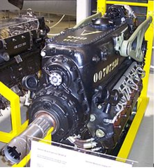
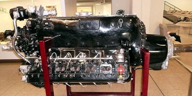
Daimler-Benz DB 605 / 616 / 620 / 625 / 628 / Weiss-Daimler-Benz DB 605B
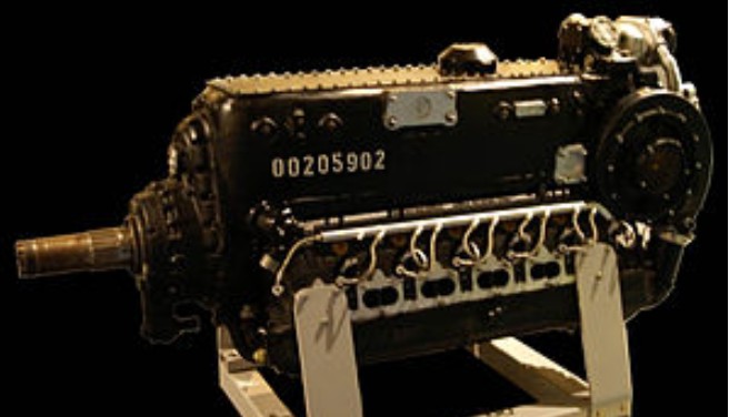
The Daimler-Benz DB 605 is a German aircraft engine, built during World War II. Developed from the DB 601, the DB 605 was used from 1942 to 1945 in the Messerschmitt Bf 109 fighter, and the Bf 110 and Me 210C heavy fighters. The DB 610, a coupled “power system” powerplant comprising a pair of side-by-side configured examples of the DB 605, geared together in the front to turn a single output shaft, was used in Germany’s only operational heavy bomber, the Heinkel He 177.
License-built versions of the DB 605 were used in the Macchi C.205, Fiat G.55, Reggiane 2005 and some other Italian aircraft. It was also initially used in the pusher-design Swedish Saab J21. IAR built the DB605 for licenced Bf-109G production. Approximately 42,400 DB 605s of all kinds were built.
The primary differences between the 605 and 601 were greater displacement, higher revolutions, higher compression ratio and a more powerful supercharger. Through careful study the engineers determined that the cylinders could be bored out to a larger diameter without seriously affecting the strength of the existing block. The difference was minimal, increasing from the 601’s 150 mm cylinder bore to the 605’s 154 mm, but this increased the overall displacement from 33.9 litres to 35.7. Altered valve timing increased the inlet period and improved the scavenging to give greater volumetric efficiency at higher speeds, which improved the maximum allowable RPM from 2,600 in the 601 to 2,800 in the 605. The combination of these changes raised power output from 1,350 PS (1,332 hp) to 1,475 PS (1455 hp). The engine was otherwise similar, notably in size, which was identical to the 601. However, its weight did increase from 700 to 756 kg.
In other ways the engine was essentially identical to the 601, being a 12 cylinder, inverted-V (with the crankshaft above the cylinders) design. Both used dual Bosch magnetos firing twin spark plugs for ignition. Fuel injection was powered by a pump supplying up to 90 bar and the oil system used three pumps with a separate 35 litre oil tank. The supercharger was fairly advanced for the era in that it used a barometrically controlled hydraulic clutch (fluid coupling) which allowed the system to automatically compensate for changes in altitude.
One major design difference was the switch from ball bearings to sleeve bearings which, when combined with increasingly poor grades of lubricants, led to serious problems in service, including engine fires; initially, for example, the use of emergency power was forbidden. Although Daimler-Benz redesigned the bearings and added oil slingers and their associated coolers, the RLM considered the DB 605 to be a “sick engine” and the problems had not been fully resolved by the end of the war.
Like the 601, the 605 was designed to run on “B4” fuel with an octane rating of 87. In 1944 a series of newer engines was introduced, allowing the engine to run on the 100 octane “C3” fuel and optionally including fittings for various optional power-boosting agent dispensing systems, such as the MW50 methanol-water injection system, and GM-1 nitrous oxide injection system. The DB 605AM, running initially on C3 and MW-50, saw power improved to 1,800 PS (1775 hp) for takeoff. In mid-1944, the requirement for C3 was dropped and standard B4 fuel with MW-50 was used. The DB 605AS(M) improved the maximum rated altitude by using a larger supercharger taken from the DB 603 but was otherwise similar to the A(M). The DB 605ASB’s takeoff power was also rated at 1,800 PS (1,775 hp), while maintaining the high-altitude performance of the ASM. The final version of the A-series was the DB 605ASC of 1945, which improved takeoff power to 2,000 PS (1,973 hp).
As early as 1942 Daimler had also been working on an upgraded D-series engine that could run on either C2 or C3 fuel. The first of these, which appeared in late 1944, were a small series of DB 605DM, followed by the main production series, the DB 605DB/DC. These engines were fitted with an adjustable screw stop which allowed the use of either B4 fuel with MW-50, or C-3 fuel without MW-50, in which case the engine was designated DB 605DB, or the use of C-3 fuel with MW-50, in which case the engine was given the -DC suffix instead. In its DB-suffix form the engine generated 1,800 PS (1,775 hp) for take-off at 1.8 ata, while the DC was capable of 2,000 PS (1,973 hp) at 1.98 ata. If MW-50 was not available for use with the B4 fuel the throttle was limited to 1.45 ata for the entire flight. Thus, this series was ideally suited to catering for the chaotic fuel supply situation prevalent during the last months of the Third Reich. These engines were mainly used in the Bf 109G-10 and K-4 series.
Variants:
Production versions
DB 605 A(M) Standard fighter engine, up to 1475 PS, 605 AM with MW-50 system up to 1800 PS
DB 605 B Same as 605 A but for use in twin-engined aircraft like Messerschmitt Bf 110, Me 210 (different prop/gear ratio)
DB 605 AS(M) Altitude optimized version of 605 A using the larger DB 603 supercharger, up to 1435 PS, ASM with MW-50 system and up to 1800 PS
DB 605 ASB(M) Altitude optimized late-war version of 605 AS using B4 fuel, ASBM with MW-50 system and up to 1800 PS
DB 605 ASC(M) Altitude optimized late-war version of 605 AS using C3 fuel, ASCM with MW-50 system and up to 2000 PS
DB 605 DM First DB 605 D version, standard MW-50 equipment, up to 1700 PS
DB 605 DB Improved 605 DM, standard MW-50 equipment, first version up to 1850 PS, later reduced to 1800 PS, B4 fuel
DB 605 DC Improved 605 DM, standard MW-50 equipment, up to 2000 PS, C3 fuel
DB 610 Two DB 605 “coupled” (geared together) as a “power system” (71.53L / 4364.8in3), to work on a single propeller shaft for use in Heinkel He 177, up to 2909 PS (2,950 hp) for take off, 2788 PS (2,750 hp) at 2,100 m. Mirror-imaged starboard component engine supercharger.
Prototype/pre-production versions:
DB 605 BS proposed version for twin-engined aircraft, derived from DB 605 AS
DB 605 E proposed version for twin-engined aircraft, derived from DB 605 D
DB 605 L Similar to 605 D but with two-stage supercharger, 2000+ PS
DB 616 A development of the DB 605.
DB 620 Coupled DB628 engines.
DB 621 A projected two stage supercharged DB605
DB 625 A turbocharged DB605
DB 628 The DB 605, fitted with a two-stage supercharger, abandoned in March 1944.
Note: All power ratings in PS (metric horsepower). Unless otherwise noted takeoff/emergency power at sea level.
Applications:
Caproni Campini Ca.183bis(intended)
Fiat G.55
Macchi C.205
Messerschmitt Bf 109
Messerschmitt Bf 110
Messerschmitt Me 210
Reggiane Re.2005
Saab 21
Savoia-Marchetti SM.91
Savoia-Marchetti SM.92
Savoia-Marchetti SM.93
VL Pyörremyrsky
Specifications:
DB 605AM
Type: 12-cylinder liquid-cooled supercharged 60° inverted Vee aircraft piston engine
Bore: 154 mm (6.06 in)
Stroke: 160 mm (6.30 in)
Displacement: 35.7 L (2,176 in³)
Length: 2,158 mm (85 in)
Width: 760 mm (30 in)
Height: 1,037 mm (41 in)
Dry weight: 756 kg (1,667 lb)
Valvetrain: Two intake and two sodium-cooled exhaust valves per cylinder actuated via a single overhead camshaft per cylinder bank.
Supercharger: Single-stage variable-speed centrifugal type supercharger driven through a barometrically controlled clutch; MW50 injection into the supercharger intake.
Fuel system: Bosch direct fuel injection
Oil system: Dry sump with one pressure and two scavenge pumps
Cooling system: Liquid-cooled, pressurized
Reduction gear: 0.594:1
Power output:
1,324 kW (1,800 PS/1,775 hp) at 2,800 rpm for takeoff with MW-50 injection
1,250 kW (1,700 PS/1,677 hp) at 2,800 rpm at 4,000 m (13,120 ft) for maximum power with MW-50 injection
794 kW (1,080 PS/1,065 hp) at 2,300 rpm at 5,500 m (18,000 ft) for max continuous
Specific power: 35.0 kW/L (0.77 hp/in³)
Compression ratio: 7.5/7.3:1 with 87-octane fuel; 8.5/8.3:1 with 100-octane fuel
Power-to-weight ratio: 1.68 kW/kg (1.02 hp/lb)
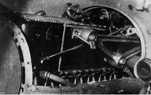
Daimler-Benz DB 604
The Daimler-Benz DB 604 was an experimental German 24-cylinder aircraft engine, which did not progress beyond the initial engine testing phase and was ultimately abandoned in September 1942.
The DB 604 was unique among the DB 600 series of aircraft engines by having its 24 cylinders arranged in an X, with four inline rows of six cylinders. The DB 604 was also unique amongst the X-24 engines, in that it was not conceived as a further development of existing Daimler-Benz aircraft engines such as the DB 601, DB 603 or DB 605, which themselves had been twinned-up as two separate powerplants sharing a new common gear reduction case at their front ends, into the “coupled” DB 606, DB 613 and DB 610 “power systems” respectively, starting before World War II.
The DB 604 was a completely new Daimler-Benz engine design featuring a perfectly square stroke ratio of 135 mm x 135 mm. The square stroke ratio enabled the relatively high engine speed of 3,200 rpm. The first engine tested in 1939 on the engine test stand achieved a power output of 1,725 kW (2,350 hp).
Further development of the first test engines led to the DB 604A/B. The only difference between the DB 604A and the DB 604B – as with the similarly suffixed A and B versions of the DB 606 and 610 “coupled” power system engines – was the direction in which the DB 604’s crankshaft turned. The DB 604A/B was equipped with a two-speed supercharger, achieving 1,835 kW (2,500 hp) whilst testing.
Development of this promising engine was canceled by the Reich Air Ministry (RLM – German:
Reichsluftfahrtministerium) in September 1942.
Specifications:
DB 604A/B
Type: Water-cooled 24-cylinder X (4 rows of 6-cylinders) piston engine
Bore: 135 mm
Stroke: 135 mm
Displacement: 46.38 L (2,830 cu in)
Dry weight: 1,080 kg (2,379 lb)
Power output: 1,835 kW (2,500 hp) at 3,200 rpm at 5,100 m (16,732 ft)
Specific power: 25.3 kW/L (0.9 hp/cu in)
Compression ratio: 7.0:1
Power-to-weight ratio: 0.59 kW/kg (0.95 hp/lb)
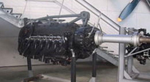
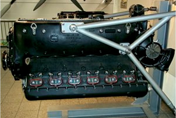
Daimler-Benz DB 603
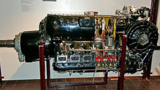
The Daimler-Benz DB 603 engine was a German aircraft engine used during World War 2. It was a liquid-cooled 12-cylinder inverted V12 enlargement of the DB 601, which was in itself a development of the DB 600.
The Mercedes-Benz T80 land speed record car, designed by aircraft engineer Josef Mickl with assistance from Ferdinand Porsche and top German Grand Prix racing driver Hans Stuck, incorporated the third prototype DB 603. It was set up for the land speed record run attempt to operate on an exotic fuel mix based on a 63% methanol, 16% benzene and 12% ethanol content, with minor percentages of acetone, nitrobenzene, avgas and ether. Adding to the power output was a pioneering form of the Luftwaffe’s later MW 50 methanol/water injection boost, and was tuned to 3,000 PS (2,959 hp, 2,207 kW) – enough, it was believed, to propel the aerodynamic three-axle T80 up to 750 km/h on a specially-prepared, nearly 10-kilometre (6.2 mi) length stretch of the roughly north/south oriented Reichsautobahn Berlin – Halle/Leipzig, which passed close to the east side of Dessau (now part of the modern A9 Autobahn) and with the actual length’s location due south of Dessau, reworked to be 25 metres (82 ft) wide with a paved-over median, for the record to be set in January 1940 during Rekord Woche (Record/Speed Week). Due to the outbreak of the war in September 1939, the T80 (nicknamed Schwarzer Vogel, “Black Bird”) never raced. The DB 603 engine was removed from the vehicle for use in fighter aircraft.
Production of the DB 603 commenced in May 1942, and with a 44.52 litre displacement figure, was the largest displacement inverted V12 aviation engine to be produced and used in front line aircraft of the Third Reich during World War II.
The DB 603 powered several aircraft, including the Do 217 N&M, Do 335, He 219, Me 410 and Ta 152C.
Variants:
Production versions:
DB 603A, rated altitude of 5.7 km, B4 fuel
Power (take-off): 1750 PS (1726 hp, 1287 kW) at 2700 rpm at sea level
Combat power: 1580 PS (1558 hp, 1162 kW) at 2500 rpm at sea level
DB 603AA DB 603A with an improved supercharger, rated altitude of 7.3 km, B4 fuel
Power (take-off): 1670 PS (1647 hp, 1228 kW) at 2700 rpm at sea level
Combat power: 1580 PS (1558 hp, 1162 kW) at 2500 rpm at sea level
DB 603E rated altitude of 7.0 km, B4 fuel
Power (take-off): 1800 PS (1775 hp, 1324 kW) at 2700 rpm at sea level
Combat power: 1575 PS (1553 hp, 1158 kW) at 2500 rpm at sea level
Prototypes and other versions:
DB 603D, a DB 603A with propellers rotating counter-clockwise; production unknown
DB 603F, a DB 603E with propellers rotating counter-clockwise; production unknown
DB 603G (production cancelled)
Power (max): 1900 PS (1874 hp, 1397 kW) at 2700 rpm at sea level
Combat power: 1560 PS (1539 hp, 1147 kW) at 2700 rpm at sea level
DB 603L/LA (prototype with two-stage supercharger, B4 fuel)
Power (max): 2000 PS (1973 hp, 1471 kW)
DB 603N (prototype with two-stage supercharger, C3 fuel)
Power (max): 2800 PS (2762 hp, 2059 kW) at 3000 rpm at sea level
Continuous: 1930 PS (1904 hp, 1420 kW) at 2700 rpm at sea level
DB 603S (DB 603A with experimental TK-11 turbo-supercharger) – Used for the Heinkel He 274 prototype airframes.
DB 613 Series of experimental “power system” coupled side-by-side twinned DB 603s, arranged as the DB 606 and DB 610 had been previously, and meant to replace the 606 and 610, in prototype form only from March 1940 through 1943.
DB 614 a 2000 PS development.
DB 615 Coupled DB 614 engines
DB 617 A long-range derivative of the DB 603
DB 618 Coupled DB 617 engines
DB 622 A DB 603 with a two-stage supercharger and single-stage turbocharger
DB 623 A DB 603 with twin turbochargers
DB 624 A DB 603 with a two-stage supercharger and single-stage turbocharger
DB 626 A DB 603 with twin turbochargers and intercooler
DB 627 The DB 603 fitted with a two-stage supercharger and after-cooler.
DB 631 An abandoned three stage supercharged DB 603G.
DB 632 A projected development of the DB 603N with contra-rotating propellers.
MB 509 Development as a tank engine for the super-heavy Panzer VIII Maus
Applications:
Blohm & Voss BV 155
Blohm & Voss BV 238
Dornier Do 217
Dornier Do 335
Fiat G.56 – two prototypes flown
Focke-Wulf Ta 152
Heinkel He 177B – prototype aircraft series
Heinkel He 219
Heinkel He 274
Macchi MC.207 – experimental installation, not flown
Messerschmitt Me 410
Reggiane Re.2006- experimental installation, not flown
Specifications:
DB 603A
Type: 12-cylinder liquid-cooled supercharged inverted Vee aircraft piston engine
Bore: 162 mm (6.38 in)
Stroke: 180 mm (7.09 in)
Displacement: 44.52 L (2,716.9 in3)
Length: 2610.5 mm (102.8 in)
Diameter: 830 mm (32.7 in)
Dry weight: 920 kg (2,030 lb)
Supercharger: Gear-driven centrifugal type supercharger
Fuel system: Direct fuel injection
Cooling system: pressurized water cooling
Power output:
1,287 kW (1,750 PS) for takeoff
1,111 kW (1,510 PS) maximum continuous
Specific power: 26.7 kW/L (0.59 hp/in3)
Compression ratio: 7.5:1 left cylinder bank, 7.3:1 right cylinder bank
Specific fuel consumption: 0.288 kg/(kW·h) (0.474 lb/(hp·h))
Power-to-weight ratio: 1.29 kW/kg (0.79 hp/lb)
Daimler-Benz DB 600
The Daimler-Benz DB 600 was a German aircraft engine designed and built before World War II as part of a new generation of German engine technology. It was a liquid-cooled inverted V12 engine first flown in December 1935, and powered the Messerschmitt Bf 110 and Heinkel He 111 among others. Most newer DB engine designs used in WW2 were based around this engine. The decision by the RLM to concentrate on manufacturing aircraft engines using fuel injection systems rather than carburettors meant that the DB 600 was quickly superseded by the otherwise similar DB 601. Later DB series engines grew in bore, stroke, and horsepower, including the DB 603 and DB 605, but were generally similar to the pattern created with the DB 600.
Variants:
DB 600A
Up to 1,000 PS (810 kW) at 2350 rpm at sea-level.
Reduction Gearing: 1.55
DB 600B
Up to 1,000 PS (810 kW) at 2350 rpm at sea level
Reduction Gearing: 1.88
DB600C
Up to 850 PS (634 kW) at 2350 rpm at 13,120 feet (3999 m)
Reduction Gearing: 1.55
DB600D
Up to 850 PS (634 kW) at 2350 rpm at 13,120 feet (3999 m)
Reduction Gearing: 1.88
DB600G
Up to 950 PS (708 kW) at 2350 rpm at 13,120 feet (3999 m)
Reduction Gearing: 1.55
DB600H
Up to 950 PS (708 kW) at 2350 rpm at 13,120 feet (3999 m)
Reduction Gearing: 1.88
Applications:
Arado Ar 197 V1. 1937 prototype – naval variant of Arado Ar 68.
Dornier Do 17 S-0 Three pre-production aircraft.
Focke-Wulf Fw 57
Focke-Wulf Fw 187 V6.
Heinkel He 60C One test aircraft.
Heinkel He 111 V5: DB 600A, B-1, B-2: DB 600C, G-4: DB 600G, G-5: DB 600C, J-1: DB 600C
Heinkel He 112 V7, V8.
Heinkel He 114 Three He 114 B-2 exported to Romania.
Junkers Ju 90 V1.
Henschel Hs 128 V1. Twin engine, pressurised cockpit, high-altitude research aircraft.
Messerschmitt Bf 109 V10 through V14. Prototypes.
Messerschmitt Bf 110 V1, V2, V3. Prototypes.
Messerschmitt Bf 162 V1, V2.
Specifications:
DB 600C
Type: Twelve-cylinder liquid-cooled supercharged 60° inverted Vee aircraft piston engine
Bore: 150 mm (5.91 in)
Stroke: 160 mm (6.30 in)
Displacement: 33.93 l (2,070.5 in3)
Length: 1,720 mm (67.72 in)
Width: 712 mm (28.03 in)
Height: 1,000 mm (39.37 in)
Dry weight: 575 kg (1,268 lb)
Valvetrain: Two intake and two sodium-cooled exhaust valves per cylinder actuated via a single overhead camshaft per bank
Supercharger: Gear-driven single-stage single-speed centrifugal supercharger
Fuel system: Four two-barrel carburetors
Fuel type: 87-octane gasoline
Oil system: Dry sump with one pressure and two scavenge pumps
Cooling system: Liquid-cooled, ethylene glycol
Reduction gear: Spur, 0.53:1
Power output: 773 kW (1,050 PS or 1,036 hp) at 2,400 rpm for takeoff
Specific power: 22.8 kW/l (0.5 hp/in³)
Compression ratio: 6.8:1
Specific fuel consumption: 302-315 g/(kW•h) (0.50-0.52 lb/(hp•h))
Oil consumption: 7-11 g/(kW•h) (0.18-0.28 oz/(hp•h))
Power-to-weight ratio: 1.34 kW/kg (0.82 hp/lb)
Daimler-Benz DB 601 / DB 606 / Aichi Atsuta / Kawasaki Ha-40 / Alfa Romeo R.A.1000 R.C.41-I Monsone
The Daimler-Benz DB 601 was a German aircraft engine built during World War II. It was a liquid-cooled inverted V12, and powered the Messerschmitt Bf 109, among others. The DB 601 was basically an improved DB 600 with direct fuel injection.
The DB 601Aa was licence-built in Japan by Aichi as the Atsuta, by Kawasaki as the Ha-40, and in Italy by Alfa Romeo as the R.A.1000 R.C.41-I Monsone.
Based on the guidelines laid down by the Reichswehrministerium (“Reich’s Ministry of Defence”), in 1929 Daimler-Benz began development of a new aero engine of the 30-litre class: a liquid-cooled inverted-Vee 12-cylinder piston engine. This was designated F4, and by 1931 two prototypes were running on the test bench. These were followed by the improved F4 B, which became the prototype for the DB 600.
In 1933, Daimler-Benz finally received a contract to develop its new engine and to build six examples of the DB 600. For the year after, the DB 600 was the only German aero engine in the 30-litre class. In total, 2281 DB 600s were built.
The DB 601A-1 was a development of the DB 600 with direct fuel injection. Like all DB 601s, it had a 33.9 litre displacement. The first prototype with the direct fuel injection, designated as F4E, was test run in 1935, and an order for 150 engines was placed in February 1937.
Serial production begun in November 1937, and ended in 1943, after 19,000 examples of all types were produced.
Variants
DB601 A-1
Up to 1,100 PS (809 kW) at sea-level with 2,400 rpm, up to 1,020 PS (750 kW) at 2,400 rpm and 4.5 km altitude, B4 fuel
DB601 Aa
Up to 1,175 PS (864 kW) at sea-level with 2,500 rpm, up to 1,100 PS (809 kW) at 2,400 rpm and 3.7 km altitude, B4 fuel
DB601 B-1/Ba
Same as DB601 A-1/Aa for use in Messerschmitt Bf 110 and/or bomber aircraft (different prop/engine ratio, 1:1.88 instead of 1:1.55)
DB601N
Up to 1,175 PS (864 kW) at sea-level and at 4.9 km altitude with 2,600 rpm, C3 fuel
Up to 1,270 PS (934 kW) at 2.1 km altitude with 2,600 rpm
DB601P
Same as DB601N for use in Messerschmitt Bf 110 and/or bomber aircraft (different prop/engine ratio, 1:1.88 instead of 1:1.55)
DB601E
Up to 1,350 PS (993 kW) at sea-level with 2,700 rpm, up to 1,320 PS (970 kW) with 2.700 rpm at 4.8 km altitude, B4 fuel
Up to 1,450 PS (1,066 kW) at 2.1 km altitude with 2,700 rpm
DB601F/G
Same as DB601E for use in Messerschmitt Bf 110, Messerschmitt Me 210 and/or bomber aircraft (different prop/engine ratio,1:1.875 (601F), 1:2.06 (601G) instead of 1:1.685)
DB606A/B
Two DB601F or G coupled to work on a single propeller shaft for use in early Heinkel He 177As – 2,700 PS (1,986 kW) at sea level with a mirror-imaged starboard component engine supercharger, and derided as “welded-together engines” by Reichsmarschall Hermann Göring in August 1942, from the problems they caused with engine fires in the He 177A during service.
Applications
DB 601:
CANSA FC.20
Dornier Do 215
Heinkel He 100
Henschel Hs 130A-0
Kawasaki Ki-60
Messerschmitt Bf 109
Messerschmitt Bf 110
Messerschmitt Me 210
Savoia-Marchetti SM.88
DB 606:
Heinkel He 119
Heinkel He 177
Messerschmitt Me 261
Licensees:
Aichi Atsuta
Alfa Romeo RA 1000 RC 41
Kawasaki Ha-40
DB 601Aa
Type: Twelve-cylinder liquid-cooled supercharged 60° inverted Vee aircraft piston engine
Bore: 150 mm (5.91 in)
Stroke: 160 mm (6.30 in)
Displacement: 33.93 L (2,070.5 in³)
Length: 1,722 mm (68 in)
Dry weight: 590 kg (1,320 lb)
Valvetrain: Two intake and two sodium-cooled exhaust valves per cylinder actuated via a single overhead camshaft per cylinder block.
Supercharger: Gear-driven single-speed centrifugal type supercharger (later, hydraulic-driven)
Fuel system: Direct fuel injection
Oil system: Dry sump with one pressure and two scavenge pumps
Cooling system: Liquid-cooled
Power output:
865 kW (1,175 PS or 1,159 hp) at 2,500 rpm for takeoff
787 kW (1,070 PS or 1,050 hp) at 2,400 rpm at 3,700 m (12,140 ft)
Specific power: 25.52 kW/l (0.56 hp/in³)
Compression ratio: 6.9:1
Specific fuel consumption: 270 g/(kW·h) (0.44 lb/(hp·h))
Power-to-weight ratio: 1.47 kW/kg (0.89 hp/lb)
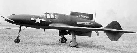
Curtiss-Wright P-55 Ascender
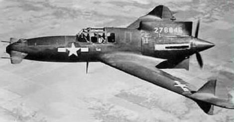
The XP-55 (Curtiss Model 249C), along with the XP-54 and XP-56, resulted from Army Air Corps proposal R-40C calling for unconventional aircraft designs. Like the XP-54, the Ascender was initially designed for the Pratt & Whitney X-1800 engine and had to be redesigned when the engine project was canceled. The XP-55 first flew on 13 July 1943 with an Allison V-1710 engine. It was to be one of the last projects supervised by Donovan Berlin before he left Curtiss to work on the P-75 project for Fisher.
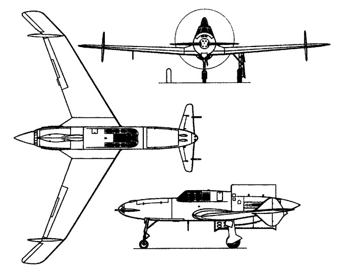
The XP-55 had a pusher engine mounted at rear, swept-back wings and forward canard mountings. The foreplane was not a canard in the true sense, but a free-floating surface with no fixed stabilizer. Its limits were 68 degrees up and down, although the down angle was restricted to 17 degrees for take-offs. Entry to the cockpit was said by test pilots to be rather awkward, requiring a telescoping ladder that was stored behind the pilot’s seat. The XP-55 was essentially a flying wing, having only vestigial vertical surfaces which were distributed on the rear fuselage and outer wings.
The XP-55 was a single-seat single-engine design. The pusher-type engine was mounted to the extreme rear and the wings were highly swept. First drawings and scale models were completed and assessed as early as 1940 to which the Army Air Corps needed more convincing. As a result, Curtiss took it upon itself to produce a flyable full scale model – this one to be designated in-house as the CW-24B. The test aircraft differed some from the final three prototypes developed from the granted contract of 1942. The test bed flew with a Menasco C68-5 powerplant, whereas the final prototype models were fitted each with the Allison V-1710 engine.
Curtiss built a full-scale flying testbed, the company Model CW-24B, powered by a Menasco C65-5 engine. The fabric-covered CW-24B went to a new US Army test site, the airfield at Muroc Dry Lake, California, for 1942 tests. These revealed serious stability problems which were only partly resolved by moving its vertical fins farther out from their initial mid-way position on the swept-back wing. The Curtiss 24 B was not a true canard, in that it had no fixed forward ‘tail’ surface. Essentially it was a flying wing with a nose mounted elevator. The 24 B made 169 flights from California’s Muroc Dry Lake, but after Curtiss-Wright had validated its concept with the CW-24B flying mock-up the USAAC ordered three XP-55 prototypes, on July 10, 1942. Armament for the XP-55 was originally drawn up to include a pair of 20mm cannon to go along with twin 12.7mm (.50 caliber) machine guns. This arrangement was revisited and revised to a quad .50 caliber array during the testing phase and this standard armament stayed with the life of the program.
For Curtiss, it would be its first design to feature a powered tricycle landing gear assembly (though fixed on the initial test models). The absence of a true rudder resulted in smaller vertical surfaces mounted far off onto the wings. The use of forward canards was also revolutionary as was the ejection system – the propeller had to be jettisoned before the pilot could eject himself. The XP-55 used a single rotation, three-bladed propeller instead of the co-axial, contra-rotating type which had been planned.
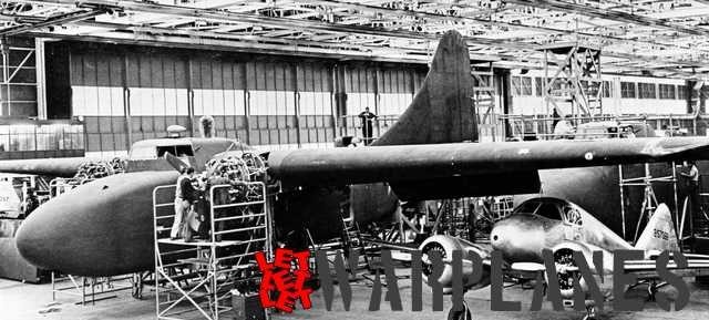
The first XP-55 (42-78845) was completed on July 13, 1943. It made its first test flight on July 19, 1943 from the Army’s Scott Field near the Curtiss-Wright St Louis plant. The aircraft experienced stability problems and underwent several modifications to increase the canard elevator surface, vertical stabilizer area, and eventually received four-foot wing tip extensions to improve stall characteristics. It was found that excessive speed was required in the take-off run before the nose-mounted elevator could become effective. Before this problem could be addressed, the first machine was lost during spin tests at St Louis on 15 November 1943. The first prototype underwent stall testing and on the third attempt the aircraft pitched forward 180 degrees onto its back and fell into the same inverted descent predicted in original Air Corps wind tunnel tests. The engine quit and nothing the pilot did could break the stall. After a perfectly stable fall of 16,000 feet, the pilot, J. Harvey Gray, bailed out safely. The aircraft continued straight down and dug a large smoking hole in the desert floor. After modifications, stall tests were performed satisfactorily, although the complete lack of any warning prior to the stall and the excessive loss of altitude necessary to return to level flight after the stall were undesirable characteristics.
The second XP-55 was flown in St Louis on 9 January 1944. The third followed on 25 April 1944 and, soon after, went to Eglin Field, Florida, for tests of its nose-mounted 12.7mm machine-guns.
The XP-55 had the advantage of being constructed largely from non-strategic materials and for a time a jet version, the company Model CW-24C, was contemplated. But lingering problems, including generally poor stability, remained unsolved when the third XP-55 was returned to Wright Field, Ohio, for further tests continuing into 1945.
An artificial stall warning device was introduced to try and correct some of these problems, and between September 16 and October 2, 1944, the second Ascender underwent official USAAF trials. The trials indicated that the XP-55 had satisfactory handling characteristics during level and climbing flight, but at low speeds and during landings there was a tendency on the part of the pilot to over-control on the elevators because of a lack of any useful “feel”. Pilot, Russ Schleeh, commented that it was terribly unstable, and that if you took your eyes off the horizon for a moment, even in the landing pattern, the plane would drift wildly off course.
The performance of the XP-55 prototype aircraft built (S/N 42-39347, 42-78845-7) was not very impressive and was in fact inferior to that of the more conventional fighters already in service. Performance was mediocre with the Allison V-1710 engine attaining only 377 mph instead of the hoped-for 500 mph. Engine cooling was also a problem. In addition, by 1944, jet-powered fighter aircraft were clearly the wave of the future. Consequently, no production was undertaken, and further development was abandoned. The third prototype survived the testing program, but was destroyed in an accident on May 27, 1945, at Wright Field, Ohio. The pilot, Captain William C. Glascow, came in low over the field during an air show, attempted a barrel roll at low altitude, and crashed. Not only was the aircraft destroyed but the pilot was killed as well as a passing motorist. The sole surviving XP-55 (42-78846) was flow to Warner Robins Field in Georgia in May of 1945. It was later taken to Freeman Field to await transfer to the National Air Museum at the Smithsonian Institution in Washington. Currently the aircraft is in the Kalamazoo Aviation History Museum undergoing a complete restoration.
The second XP-55 has survived and is among numerous historically valuable airframes held by the Smithsonian Institue’s National Air and Space Museum in Washington D.C.
The name Ascender had originated as a joke on the part of a Curtiss engineer, a reference to the aircrafts rather odd design which was not appreciated by the congressional oversight committee. The name stuck, and eventually became official.
Curtiss-Wright XP-55 Ascender
Engine: 1 x Allison V-1710-95 liquid-cooled V12, 1,275hp, 951kW
Length: 29 ft 7 in (9.02 m)
Wingspan: 40 ft 7 in (later 44 ft 6 ft)
Wing area: 209.0 sq ft / 19.41 sq.m later 21.83 sq.m / 234.98 sq ft
Height: 9.84ft (3.00m)
Empty Weight: 6,354lbs (2,882kg)
Maximum Take-Off Weight: 7,710lbs (3,497kg)
Maximum Speed: 390mph (628kmh; 339kts) at 19,300 ft (5,885 m)
Service Ceiling: 34,600ft (10,500m)
Climb to 20,000 ft (6,095 m): 7 minutes 6 seconds
Range: 635 miles (1,022 km)
Armament: 4 x 12.7mm (0.5 in) Colt Browning M2 machine guns in nose
Crew: 1
CW-24B
Engine: Menasco C68-5, 275 hp, 633kW
Curtiss-Wright C-76 Caravan
Transport, USA, 1943
Engine: 2 x Pratt & Whitney R 1830-92 Twin Wasp, 1184 hp
Length: 68.34 ft / 20.83 m
Wingspan: 108.169 ft / 32.97 m
Max take off weight: 28003.5 lb / 12700.0 kg
Max. speed: 174 kts / 322 km/h
