UK The Fane Aircraft Company Limited was a British company formed by the aviator Captain Gerard Fane, DSC, and based at Norbury, London, England.
It was originally formed as Comper Fane Aircraft Limited (sometimes C.F. Aircraft) in August 1939, incorporating the name of his former collaborator and aircraft designer, the late Nicholas Comper. On 6 April 1940 the name was changed to the Fane Aircraft Company Limited.
The company’s only aircraft was based on the Comper Scamp. The Scamp had been designed by Nicholas Comper as a two-seater but he had not built it, redesigning it as a single seater, the Comper Fly. Fane took the Scamp design and reworked it as the Fane F.1/40 which first flew in 1941; with no orders from the Air Ministry only one was built.
On 10 August 1944 the company changed its name to Fane Engineering Designs Limited.
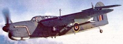
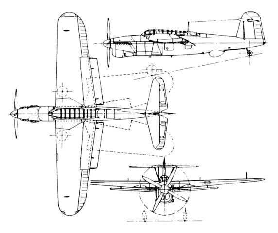
The original S.24/37 Barracuda was designed around the Rolls-Royce Exe 24-cylinder X-type engine but early in the construction stage the power plant was changed to the Rolls-Royce Merlin 30. This Merlin-engined prototype first flew on 7 December 1940. The first prototype Barracuda had an unbraced tailplane in line with the top of the fuselage but during the early trials it was found that when the flaps were in the diving position the disturbed air caused serious tail flutter. To overcome this the tailplane of the second prototype was raised 1.22m to clear the wake from the flaps and also to clear the folding wings. The first trials with the repositioned tail unit were made in July 1941 and eliminated the problem. The Barracuda was first used operationally in September 1941 in raids from HMS Victorious on Kirkenes in northern Norway and on Petsamo in Finland. The first monoplane torpedo bomber to go into service with the FAA. In 1942 Barracudas took part in sweeps over French ports and in the invasion of Madagascar. The first major action in which Barracuda squadrons took part was the successful bombing attack on the German battleship Tirpitz in Alten Fiord, north Norway on 3 April 1944. It was in action against the Japanese for the first time in an attack on enemy installations at Sabang, on the island of Sumatra on 19 April 1944. Production of the Barracuda ended in 1946, by which time 2582 had been built: as the Barracuda I with a Merlin 30 engine; Barracuda II with a 1,222kW Merlin 32 engine; Barracuda III, similar to the Mk II but with ASV 10 radar equipment in a bulge under the fuselage; and Barracuda V (first flown in June 1945) with a Rolls-Royce Griffon VII engine driving a Rotol four-bladed propeller, increased wing span, larger rudder and fin, generally strengthened structure, no rear armament but one 12.7mm forward-firing machine-gun.
Fairey Barracuda Mk II Length: 39 ft 9 in / 12.12 m Height: 15 ft 1 in / 4.6 m Wingspan : 49 ft 2 in / 14.99 m Wing area : 413.983 sqft / 38.46 sq.m Max take off weight : 14253.1 lb / 6464.0 kg Weight empty : 10819.9 lb / 4907.0 kg Max. speed : 208 kts / 386 km/h Cruising speed : 178 kts / 330 km/h Service ceiling : 16601 ft / 5060 m Wing load : 34.44 lbs/sq.ft / 168.0 kg/sq.m Maximum range : 999 nm / 1851 km Engine : Rolls Royce Merlin 32, 1618 hp / 1223kW Crew : 3 Armament : 2x cal.303 MG (7,7mm), Torpedo 735kg / 726kg Bomb
In September 1934 Fairey produced a brochure which described and illustrated the Fairey P27/32 as a universal design, being able to take on a number of different shapes each suited to a particular operational role.
Their first venture into the all-metal monoplane field, in which light-alloy stressed-skin construction was employed, the oval-section monocoque portion was of light-alloy hoop frames, pressed out in single pieces, each being notched to receive four special section longerons and the pre-formed skin plating. The skin plating was cut to form strips of clinker construction with the upper edge rolled to form an integral U-section stringer. After the first strip of fuselage skin had been attached to the frames, the next strip was applied with a small overlap on the previous skin, along which a closing rivet line was centred. This “stringerless” method of construction thus saved the weight of numerous long rivet lines which would have attached the separate stringers had they been employed.
The four TT-sectioned longerons, arranged as upper and lower pairs, ran three-quarters the length of the fuselage, with the inner flanges of each longeron connecting to each frame by of small brackets. A butted flat skin joint was arranged above each longeron, closure being made by a double rivet line through each skin and the outer flange on each side of the longeron.
The fuselage forward of the pilot’s bulkhead comprised the steel tube structure supporting the pilot’s cockpit flooring and the fireproof bulkhead. Light alloy subframes and sections formed the fuselage profile and sections to which fixed and detachable light-alloy panels were fitted. The power plant picked up with fittings on the firewall together with a light tubular structure which carried the detachable cowling panels.
The small centre section to the wing comprised two short lengths of spar, built up from light-alloy box sections into a girder structure, joining four heavy wing ribs. The spaces formed by the two pairs of ribs at the outboard ends each housed a large fuel tank, whilst the larger space between the inner ribs formed the bomb aimer’s compartment which was entered from the cockpit interior by means of a large aperture in the top skinning of the centre section.
Battle production in Fairey’s Stockport factory
The outer wing panels were of two-spar construction, the inner ends of girder form, changing in section to flanged beams on the outboard sections. Wing ribs containing large circular flanged lightening holes and further strengthened by deep edge flanges were pressed from light-alloy and were attached to the spars by means of angle brackets. Notched in a similar way to the fuselage frames, the wing ribs supported continuous Z section spanwise stringers, this time separate from the wing skinning. The lightalloy wing skin was applied in long flat strips, overlapped as on the fuselage skins, with single rows of rivets through the overlap and the Z stringer flange below. The underside skinning was fitted with screwed panels running spanwise, adjacent to the flying control runs and bomb release gear.
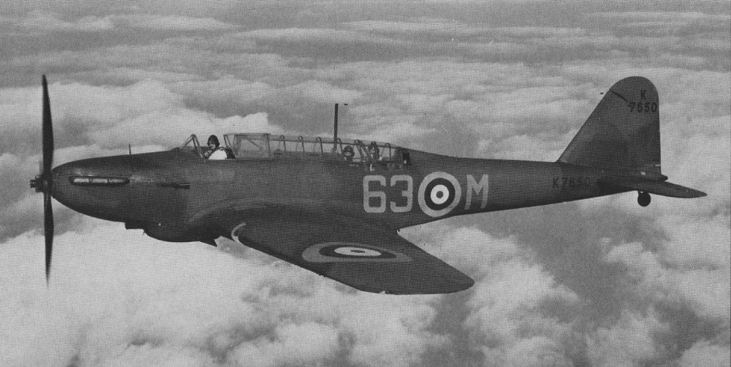
All of the movable control surfaces were of metal framing with fabric covering. The split trailing edge flaps were of metal throughout and were interconnected at their inner ends via universal joints. A simple hydraulic system was provided which powered the flaps, main undercarriage legs, and the bomb mounting crutches. The latter permitted the bombs to be lowered clear of the wings during dive bombing. The undercarriage jack bodies were fixed attachments, whilst the ram was free to run within guides to which the leg radius rod was attached. From the fully retracted position, the first half-inch of movement of the ram unlocked the holding-up latch allowing the leg to drop down. When fully extended, self-locking was provided by the angular position of the radius rod. The separate cockpit hoodings as on the mock-up were dispensed with on the prototype P27/32, and a single long glazed hooding was fitted which joined the two positions. Although this subsequently was found to have spoiled the pilot’s rearward view, it did much to improve the air flow and lessen wind noise around the cockpit area as discovered on wind tunnel model tests. However before the prototype machine had reached the flying stage, a contract was received for an updated airframe with the specific requirement that a third crew member must be carried so that the rear gun could be manned at all times. This was regarded with complete horror at Hayes, and brought forth further demands from C. R. Fairey that the single-engined design be replaced with the twin-engined design. In subsequent meetings it soon became clear that a production contract was being offered provided a minimum performance could be guaranteed by the company. When Mr Fairey asked what that would be in terms of speed, the answer was not less than 195mph at 15,000 feet with full load and a crew of three. Because Mr Fairey was expecting nothing less than 270mph at that altitude with a crew of two, the guarantee was given and the production contract to Specification P23/35 was issued for no less than 155 machines. However further slippage in the delivery date of the first Merlin ‘C’ engine to Hayes, coupled with less satisfactory power output figures, did much to cause frustration in the experimental flight shed at Heathrow and greater concern at the Hayes Design Office end that the performance of the P27/32 would not reach the expected 270mph figure. In the meantime everything possible was being done to make the prototype as aerodynamically clean as possible and a further weight saving campaign was initiated. The prototype made its first flight from the Great West Aerodrome, in the hands of Flt Lt Chris Staniland, on March 10, 1936. Then fitted with a fixed-pitch three-bladed Fairey metal propeller it soon brought praise from an enthusiastic Staniland, although he was later to report that during high speed flight with the hood open the entire canopy was in danger of being ripped off. This matter was put to right when the final mock-up of the rear gun installation was approved, which enabled the final form of the hooding to be settled. The single Vickers ‘K’ gun was mounted on the familiar Fairey high-speed gun mounting, only this time with the difference that the mounting could be collapsed into a rotating cone which enabled the retracted gun to be rotated beneath the fuselage skin leaving a completely unbroken and smooth line to the rear fuselage. When finally flying in this form, and with the de Havilland two-position, three-bladed propeller, and the new letter-box exhaust manifolds as fitted to the RollsRoyce F25 engine, the Battle probably reached the peak of its perfection. Shallow dive bombing with the pilot aiming and releasing the bomb load was thought to be the P27/32’s most suited role, and was one it was thought possible to operate with a two-man crew; but at this stage the fate of the machine was more or less sealed as an underpowered, three-seat, light, day reconnaissance/bomber. On paper at any rate the Martlesham Heath trials showed that even under these limitations the Battle could almost make 260mph and could nearly cover 1,100 miles when flying at 200mph, and during the late summer of 1937 the Hayes Design Office concentrated on a weight saving version under the official classification of, the Battle Mk II in an effort to make the best of what had been conditioned by the Air Ministry. The first production Battle Mk I had flown from Ringway at some time during April 1937 and first arrived at the Great West Aerodrome on May 10, 1937, and subsequently went to Martlesham Heath on July 6 for its acceptance trials. Here some grim revelations were recorded, for at the new increased all-up weight the Battle Mk I K7558 could only reach 238mph at 15,000 feet. On this basis comparative figures for the light, long-range Mk II project appeared more promising indicating a restoration of the maximum speed to 255mph at 15,000 feet, with a range in excess of 1,400 miles. But in August 1937 all such hopes of performance improvement came to a halt.
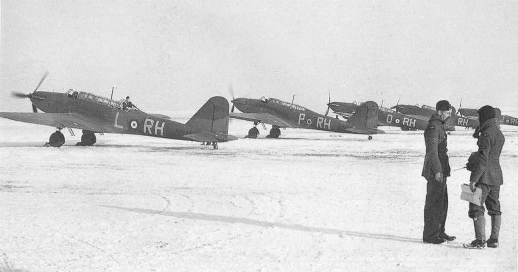
No.88 Sqn RAF
Already hundreds of Battles were beginning to take shape under the Shadow Factory Scheme and interest from Dominion and several other governments was strong. Starting in late 1935 with the company’s desire to fit a super power unit in place of the thwarted P16, designs soon evolved using first the Vulture and then the P24. When the virtual failure of the Vulture led to its replacement by the Exe and the Sabre, it was soon established that the Battle was capable of easily being converted to any suitable power unit, and the idea of a flying engine test bed was soon established. In response to demands for dual-control trainers and bombing and gunnery training conversions, detailed project drawings soon established that the changes could easily be effected at minimum cost in time, money, materials and manhours. When these facts were realised and that ex operational airframes could be retrospectively converted, the Battle appeared to have the chance of an extremely long and active life, thus in a short time hundreds more Battle orders were rushed through. Fairey production and technical resources were stretched to the limit with these undertakings in spite of having the separate Stockport factories to undertake most of the development work. The 10 squadrons of Battle bombers of the Advanced Air Striking Force found themselves in France on September 1, 1939. With no visible signs of war taking place and prevented from aggressive action by the British Government ruling that bombing could not be directed against land targets, the Battles were employed on high altitude – photo-reconnaissance work across the German frontier, and later still to leaflet dropping sorties. These missions were undertaken in daylight without fighter protection and losses were severe, but these actions were nothing in comparison with the odds faced some six hours after the German attack had been launched on May 10, 1940, when the remains of the Battle squadrons were released to carry out their first bombing attacks on the enemy. The rear gunner of a Battle of No 88 Squadron Advanced Air Striking Force shot down a Messerschmitt Bf 109E over France on 20 September 1939: the first RAF aircraft to shoot down a German aircraft during World War II. All told, the Air Ministry ordered some 2,419 Battles for the RAF, Dominion and foreign air forces. Of this total only 2,185 were built (1 by Hayes; 1,155 by Stockport and 1,029 by Austin). Sixteen were ordered by Belgium, which were built separately by Stockport, thus the total number of Battles constructed was 2,201.
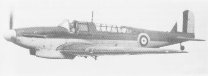
Battle T66
The type also served with the air forces of Australia, South Africa and Turkey.
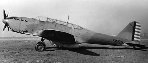
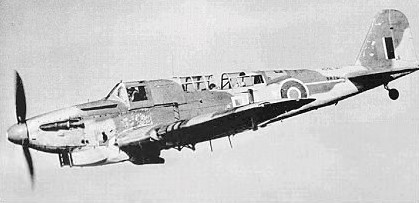
One Battle, serial K9370, was fitted with the Fairey P.24 engine and Fairey electrically operated contra-rotating constant-speed propellers – the first propellers of this type to be flight tested in the UK. First flying on 30 June 1939, to 5 December 1941 the aircraft accumulated about 86 flying hours at the hands of Flt Lieut Christopher Staniland, Mr F. H. Dixon (the company’s subsequent chief test pilot) and a number of RAF pilots.
Fairey Battle with Fairy P24 Monarch engine and coaxial propellers
It was then shipped to the USA.
Fairey Battle with Fairy P24 Monarch engine and coaxial propellers
Prototype Battle Mk I Engine: Rolls-Royce Merlin F, 12-cylinder 60 deg Vee, liquid cooled, 890bhp for take-off, 1,035bhp at 12,000ft. Wing span 54ft. Length 42ft 7in (tail up). Height 15ft (tail up). Root chord 11ft 4 in. Tip chord 5ft. Propeller dia: 11 ft 6in (or 12ft). Wing area: 422 sq ft. Track 9ft 8in. Empty wt: 6,647 lb. Loaded wt: 10,792 lb. Wing loading: 25.6 lb/sq ft. Power loading: 10.4 lb/hp (take-off), Power loading: 10.9 lb/hp (supercharged). Max speed, level: at SL: 210mph Max speed, level: at 5,000ft: 226mph Max speed, level: at 10,000ft: 240mph Max speed, level: at 15,000ft: 257mph Max speed, level: at 20,000ft: 245mph Max speed, level: at 25,000ft: 215mph. Cruise at 16,000ft: 200mph. Landing speed: SL 60mph. Climb to 5,000ft: 4 min 6 sec Climb to to 10,000ft: 8min 24sec Climb to to 15,000ft: 13min 36sec Range at 16,000ft at 200mph: 1,100 mile Range at 16,000ft at 257mph: 650 mile.
Fairey Battle Mk.I Engine : Rolls Royce Merlin Mk.I, 1016 hp Length: 52.067 ft / 15.87 m Height: 15.486 ft / 4.72 m Wingspan : 54.003 ft / 16.46 m Max take off weight : 10793.5 lb / 4895.0 kg Max. speed : 210 kts / 388 km/h Service ceiling : 23491 ft / 7160 m Range : 913 nm / 1690 km Crew : 3 Armament : 2 MG 455 kg Bomb
Mk.III Engine: Rolls-Royce Merlin III, 1440 hp / 755kW Wingspan: 16.5 m / 54 ft 2 in Length: 15.9 m / 52 ft 2 in Height: 4.7 m / 15 ft 5 in Wing area: 39.2 sq.m / 421.94 sq ft Max take-off weight: 4900 kg / 10803 lb Empty weight: 3000 kg / 6614 lb Max speed: 257 mph @ 15,000 ft Cruise speed: 338 km/h / 210 mph Ceiling: 7000 m / 22950 ft Range w/max.fuel: 1600 km / 994 miles Armament: 2 x .303 machine-guns, 500kg of bombs Crew: 3
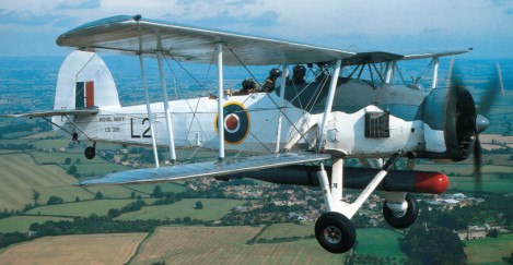
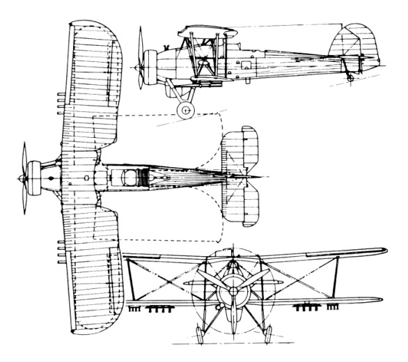
In 1933 the Fairey Aviation Company privately financed and built the TSR.1, a biplane torpedo spotter reconnaissance aircraft, from which the Swordfish evolved. Although the first TSR.I crashed, it had undergone sufficient tests to prove the feasibility of the design, and Fairey built the TSR.II, a slightly larger aircraft. It was designed by Marcelle Lobelle to meet the Naval Spec S.15/33.
First flying from Harmondsworth on 17 April 1934, and after numerous modifications a specification (S.38/34) was written around the aircraft. Official testing proved it to be a stable and reliable aircraft. The fuselage, 36ft 4in long, was rectangular in section and featured a bolted steel tube frame. The aft portion was fabric covered, but detachable metal panels, for easy access, were fitted from the cockpit forward. The crew consisted of a pilot, navigator and bomb-aimer. The equal span biplane wings were of fabric covered metal construction, and the upper wing centre section was attached to the fuselage by a pyramid structure and carried the hoisting sling. The lower wings were braced to the fuselage by an inverted V strut. The wing cellules could be manually folded for compact storage. The leading edge of the upper wing was fitted with Handley Page slots, and ailerons were fitted to both upper and lower wings. The undercarriage used medium pressure tyres and pneumatic brakes. Each of the main units consisted of an oleo shock absorber leg connected to the lower centre section front spar, and two inner struts hinged to the fuselage. The design was strengthened to withstand catapult launches and arrester hook landings. Early production Swordfish, built to Air Ministry Specification S.33/34, were powered by an air cooled 690 hp Bristol Pegasus IIIM3 radial engine. Blessed with superb handling characteristics, the Swordfish performed extremely well on carrier borne operations, being able to operate from pitching decks in stormy conditions. It had a range of 546 miles and a maximum speed of 138 mph at 5,000ft.
The propeller was a three-blade Fairey-Reed metal.
The Swordfish carried 155 Imp.Gal / 705 lt of fuel in its min tank and 12.5 Imp.Gal / 57 lt in a gravity tank, both behind the Pegasus IIIM3 or Mk.30 engine.
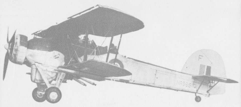
The first batch of production Fairey Swordfish rolled off the assembly line during December 1935, and were operating with the Royal Navy’s Fleet Air Arm (FAA) within two months. By 1939, on the eve of the Second World War, there were 13 operational squadrons of the type. A total of 689 aircraft had been delivered or were on order. The Swordfish Mk I’s defensive armament comprised a fixed forward firing synchronised Vickers machine gun and a movable Vickers K gun on a Fairey high speed mounting in the rear cockpit. The offensive load could be a single 18in 1,610 lb torpedo, or one 1,500 lb mine, or 1,500 lb of bombs. The Mk II, which appeared in 1943, had a strengthened lower wing capable of carrying eight 601b rocket projectiles. The final production version, the Mk III, had an ASV Mk X radar scanner in a radome under the fuselage. In Canada, canopy equipped Mk.IIs and IIIs were designated Mk IVs. The No 1 Naval Air Gunners School at Yarmouth, Nova Scotia, operated 105 Swordfish. Considered obsolete at the beginning of the war, the Swordfish outlived its successors and survived the war with an impressive battle record; the type is credited with sinking a greater tonnage of Axis shipping than any other torpedo bomber.
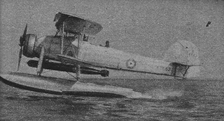
The Swordfish first made big news in the seaplane form, when a Swordfish catapulted from HMS Warspite not only spotted for the British naval force during the battle in Ofot Fiord, Norway, on April 13, 1940, but itself bombed and sank a submarine and fin¬ished off an enemy destroyer that had been dam¬aged by the ships. Seven months later, Swordfish from the carrier Illustrious achieved one of the most spectacular successes in naval air warfare. In two waves or twelve and nine aircraft, they dived into Taranto Harbour under cover of darkness and launched their bombs and torpedoes to such effect that three Italian battleships, a cruiser and two destroyers were seriously damaged, two naval auxiliaries sunk and shore installations heavily damaged all for a loss of two Swordfish. Another major success was achieved on May 26, 1941, when Swordfish of 818 Squadron so crippled the battleship Bismarck that the Navy was able to intercept and sink it. The well remembered attack on the Scharnhorst and Gneisenau in the Channel cost the lives of 13 of the 18 men who took part. Outliving its intended replacements, the Fairey Albacore and Barracuda, the Swordfish served until the war’s end. Production ended on 18 August 1944, by which time a total of 2,396 Swordfish were built.
Engine: Bristol Pegasus, 690 hp Wingspan: 45 ft 6 in Length: 36 ft 4 in Takeoff weight: 9250 lb Max speed: 139 mph Seats: 2-3
Swordfish Mk II Engine: 1 x Bristol Pegasus XXX, 559kW / 740 hp Max take-off weight: 3406 kg / 7509 lb Empty weight: 2132 kg / 4700 lb Wing loading: 12.3 lb/sq.ft / 60.0 kg/sq.m Wingspan: 13.87 m / 45 ft 6 in Length: 10.87 m / 35 ft 8 in Height: 3.76 m / 12 ft 4 in Wing area: 56.39 sq.m / 606.98 sq ft Max. speed: 120 kt / 222 km/h / 138 mph Cruise speed: 104 kt / 193 km/h / 120 mph Service ceiling: 3260 m / 10700 ft Range: 1658 km / 1030 miles Armament: 2 x 7.7mm machine-guns, 1 x 730kg torpedo or 680kg of bombs Crew: 2-3
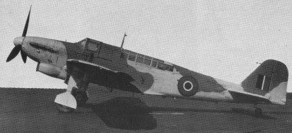
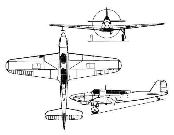
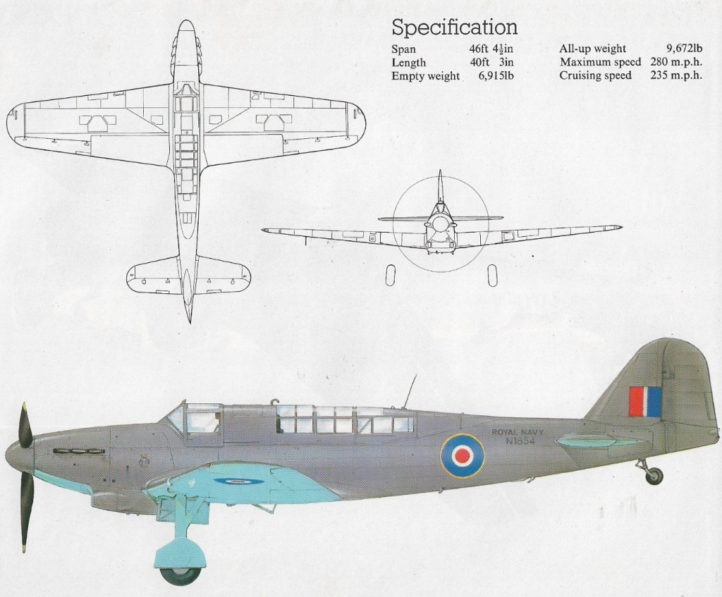
First flown on 4 January 1940, there was no prototype as such for the Fulmar, which was evolved in 1939 from the P.4/34 lightweight development of the Fairey Battle day bomber. The urgent need by the Fleet Air Arm (FAA) for a new fighter led to a rapid trials programme, beginning on January 4, 1940, with the maiden flight of N1854, the first production Fulmar, of which 250 were ordered. The Fulmar I was an all metal cantilever monoplane, with folding wings for carrier stowage; the semimonocoque fuselage housed the deck arrester gear and catapult points, and space was provided for an inflatable dinghy.
The pilot’s cockpit was separated from that of the observer/navigator, and both were enclosed by perspex canopies following the contours of the fuselage. The wide track undercarriage retracted inwards towards the wing roots. The powerplant for all except two early Fulmar 1 aircraft was the 1080 hp Rolls¬Royce Merlin VIII engine. Due to the additional weight of a second crew member, and the special equipment required for carrier operation, the Fulmar did not achieve the same rate of climb or airspeed as its land-based counterparts although this was not necessarily required by the Royal Navy. Armament was very similar to the best in the RAF, consisting of eight 0.303 in (7.7 mm) Browning machine guns four in each wing with twice the ammunition capacity of the Spitfire and Hurricane. The lack of a rear defensive gun was one of the Fulmar’s principal deficiencies, and some crews unofficially fitted an additional gun of their own choice in the rear cockpit.
N1858 – the 5th Fulmar I
Deliveries of the Fulmar I began in June 1940, to 806 Squadron, and it became operational aboard the aircraft carrier Illustrious about two months later. A total of 250 853kW Rolls-Royce Merlin VIII-powered Mk Is were built. At this time, Fairey had plans for the development of the Fulmar II, to be powered by the 1300 hp / 969kW Merlin 30, and with weight reductions brought about by the use of lighter constructional materials. This enabled the Fulmar II to carry the originally intended bombload in the form of a single 113.4 kg (250 1b) or 227 kg (500 1b) bomb beneath the fuselage (the Mk I being limited to eight 9 kg [20 1b] or 11.3 kg [25 1b] bombs under the wings). The Fulmar Mk II with nearly 300 more horsepower, was only 16km/h faster than the Mk I.
Orders for 350 Fulmar IIs were placed during the autumn of 1940, bringing the total number on order to 600. With conversions to Fulmar II beginning on the Mk I production line, the eventual result was that well over 400 were completed as Mk IIs. Ammunition capacity of the Fulmar II was eventually increased from 750 to 1000 rounds per gun but, despite this, the aircraft’s fighting ability was still disappointing. Although short on speed and manoeuvrabil¬ity, it served with 14 FAA squadrons, accounting for more than 100 enemy aircraft until the appearance of more advanced types such as the Seafire and Firefly. During the summer of 1941, four 0.3 in (12.7 mm) machine guns were fitted to one Fulmar. Firing trials proved satisfactory, and the last 100 aircraft were adapted for such an armament, but not all were equipped due to an insufficient supply of the heavier guns. Fulmars were used quite successfully as convoy escorts during the mid war years, and about 100 were converted into makeshift night fighters. In 1943 they were gradually withdrawn from front line service and reassigned to training duties.
Fairey Fulmar Mk.I Engine: 1 x Rolls-Royce Merlin VIII, 805kW / 1065 hp Max take-off weight: 4853 kg / 10699 lb Empty weight: 3955 kg / 8719 lb Wing loading: 31.37 lb/sq.ft / 153.0 kg/sq.m Wingspan: 14.14 m / 46 ft 5 in Length: 12.24 m / 40 ft 2 in Height: 4.27 m / 14 ft 0 in Wing area: 31.77 sq.m / 341.97 sq ft Max. speed: 215 kts / 398 km/h / 247 mph Service ceiling: 6555 m / 21500 ft Endurance: 4 h Armament: 8 x .303in / 7.7mm machine-guns Bombload: eight 9 kg [20 1b] or 11.3 kg [25 1b] bombs Crew: 2
Fairey Fulmar Mk.II Engine: 1 x Rolls-Royce Merlin 30, 1300 hp / 969kW Span: 14.13 m (46 ft 4.5 in) Length: 12.24 m (40ft 2 in) Gross weight: 4695 kg (10350 lb) Maximum speed: 417 km/h (259 mph) Bombload: 113.4 kg (250 1b) or 227 kg (500 1b) bomb
Founded by C R. (later Sir Richard) Fairey, initially to build 12 Short 827 seaplanes. Leased premises at Hayes, Middlesex, replaced by new factory 1917-1918. Became a public company March 5,1929 and the following year opened new airfield at Harmondsworth, later requisitioned and incorporated in site for London’s Heathrow Airport. Reorganized as holding company The Fairey Company Ltd. March 31,1959, aircraft manufacturing subsidiary becoming Fairey Aviation Ltd. and the Stockport plant Fairey Engineering Ltd. Fairey Aviation Ltd. merged with Westland Aircraft Ltd. in 1960. Britten-Norman (Bembridge) Ltd. acquired 1972. Fairey group into liquidation 1977; engineering activities acquired by National Enterprise Board; Britten-Norman operated by liquidator pending sale.
Company designs included F.2 twin-engined biplane fighter; camber-changing trailing-edge flaps introduced on Hamble Baby. Fairey III series introduced 1917; final model IIIF entered production 1926 and declared obsolete 1940. Fairey Hendon (1930) was the first British cantilever monoplane heavy bomber; Long-range Monoplane captured absolute distance record for Britain 1933. The famous Fairey Swordfish (“Stringbag”) torpedo bomber entered production in 1936; 2,392 were built by Fairey and Blackburn; it was the only biplane to remain in service throughout Second World War. Other famous aircraft included Battle light bomber, Fulmar fleet fighter, and Barracuda dive-bomber. Firefly name revived for Rolls-Royce Griffon-powered monoplane which entered FAA service in 1943, serving in Korea in 1950. First FAA aircraft to combine search and strike roles was the Gannet with Double Mamba coupled turbines; developed Gyrodyne convertible helicopter 1946; Jet Gyrodyne 1953; Rotodyne compound helicopter airliner 1957. Fairey Delta 2 research aircraft set world air speed record of 1,822km/h on March 10, 1956.
Sir Richard Fairey died at the end of 1956
Britten-Norman became Fairey Britten-Norman in 1974. Faiery Aviation joined Westland in 1961.
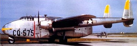
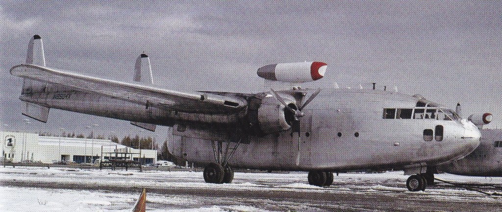
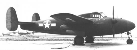
For a US Army requirement of 1941 for a specialised military freighter, Fairchild began work on the design of its Fairchiid F-78. Following approval of the design and a mock-up in 1942, a contract for a single prototype was awarded and the designation XC-82 allocated.
The XC-82 was a cantilever high-wing monoplane of all-metal construction, the fuselage incorporated a flight deck for a crew of five and a large-capacity cabin/cargo hold with clamshell doors at the rear to provide easy access for wheeled ortracked vehicles. The rear doors could be removed completely for the deployment of heavy loads by parachute extraction techniques, could accommodate 78 persons for emergency evacuation, 42 fully-equipped paratroopers or 34 stretches.
The undercarriage was a retractable tricycle and power was two 1566kW Pratt & Whitney R-2800-34 Double Wasp 18-cylinder radial engines in wing-mounted nacelles. Extending aft from these nacelles were tail-booms carrying twin fins and rudders and united at the rear by the tailplane mounting a single elevator.
First flown on 10 September 1944, the US Army Air Force placed an initial contract for 100 C-82A aircraft, named Packet. The first were delivered for evaluation in 1945 and a contract for 100 more followed.
Fifty-two were modified as AC-119G Shadow and AC-119K Stinger gunships.
Because of wartime demands a second production line was laid down by North American Aviation at Dallas, Texas, but from a contract for 792 C-82N only three were completed as North American NA-135 before the contract cancellations that followed VJ Day. Fairchild eventually built a total of 220 with deliveries ending in 1948.
The Packet serviced to the USAF’s Tactical Air Command and Military Air Transport Service until it was retired in 1954.
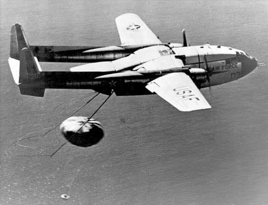
During 1947 Fairchiid developed an improved version of the C-82, the XC-82B prototype being a conversion from a production C-82A. It differed primarily by having the flight deck resited into the nose of the aircraft and the installation of 1976kW Pratt & Whitney R-4360-4 Wasp Major 28-cylinder radial engines. Following service tests it was further modified and ordered into production as the C-119B Flying Boxcar.
In 1964 Steward-Davis Inc converted C-82A N74127 to a Skytruck I with higher weights, performance, and hot-air de-icing system. The MTOW increased to 60,000 lb.
The 1965 Steward-Davis Inc Skypallet was a C-82A design with the fuselage floor separating from the aircraft from nose to tail for large cargoes, and fitted with an internal hoist. One was converted; N4828V.
C-82A Engines; 2 x Pratt & Whitney R-2800 Double Wasp, 1566kW Wingspan; 32.46 m / 106 ft 6 in Length; 23.5 m / 77 ft 1 in Height; 8.03 m / 26 ft 4 in Loaded weight; 24300 kg / 53573 lb Max. speed; 400 km/h / 249 mph Cruise speed; 260 km/h / 162 mph Ceiling; 8000 m / 26250 ft Range w/max.fuel; 3400 km / 2113 miles Crew; 5 Payload; 78 passangers or 42 paratroopers
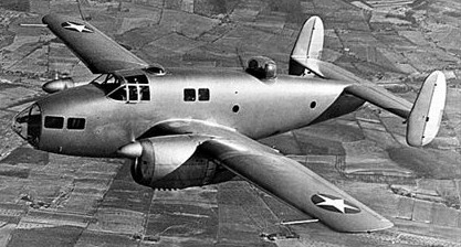
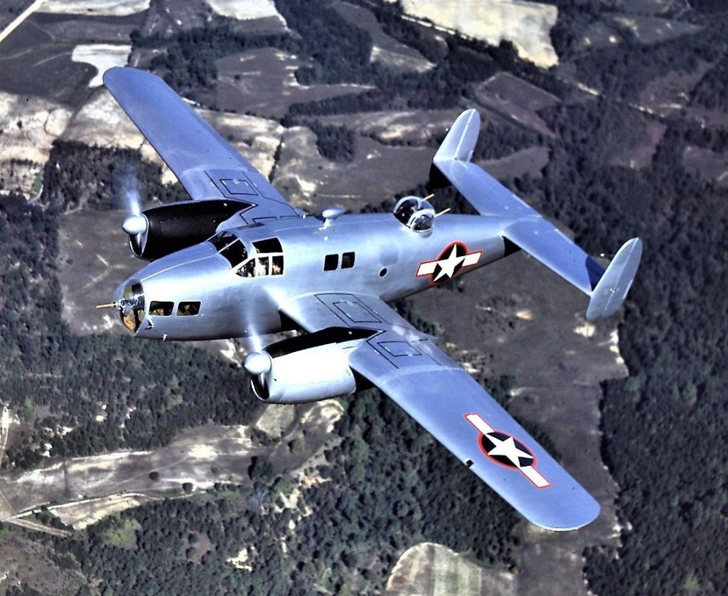
The increasing importance and complexity of multi-engined aircratt fitted with power-operated turrets compelled the development for the USAAF of a specialist trainer. The all-plywood XAT-13 medium bomber crew trainer with two 447-kW (600-hp) R-1340-AN-1 radials, a ball-mounted nose gun, a turret-mounted dorsal gun, a small bomb bay and, in addition to an instructor, stations for a pilot, bomb-¬aimer, navigator, gunner and radio operator, met that requirement.
The USAAC ordered two specialised gunnery trainer prototypes from Fairchild. The first (XAT-13) was intended to provide team training for a bomber aircraft’s entire crew, and this aircraft was powered by two Pratt & Whitney R-1340-AN1 Wasp 9-cylinder radial engines.
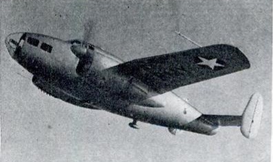
The second prototype (XAT-14) was of similar layout and powered by two 388kW (520-hp) Ranger V-770-6 inline engines. It was adapted subsequently as a specialised trainer for bomb-aimers, with its defensive guns removed, under the designation XAT-14A. Testing and evaluation of these aircraft resulted in the procurement of a specialised gunnery trainer under the designation AT-21 Gunner.
A cantilever mid-wing monoplane of mixed construction, the AT-21 had a deep oval-section fuselage, a tail unit incorporating twin fins and rudders and retractable tricycle landing gear. Accommodation was provided for a crew of five, including pilot, co-pilot/gunnery instructor and three pupils.
The AT-21 production type, was optimised for gunnery training with a two-gun turret but no bomb bay.
AT-21-BL
Of the 175 AT-21s constructed, 106 were built by Fairchild and, to speed deliveries to the USAAF, 39 were built by Bellanca Aircraft Corporation and 30 by the McDonnell Aircraft Corporation at St Louis. Entering service with newly-established air gunnery schools, the AT-21s remained in service until 1944, when they were displaced by training examples of the operational aircraft in which the air gunners would eventually serve. Many of these surplus aircraft were then converted for use as target tugs.
XAT-13 Engines: 2 x R-1340-AN-1 radials, 447-kW (600-hp).
XAT-14 Engines: 2 x Ranger V-770-6 inlines, 388-kW (520-hp).
AT-21 Engine; 2 x Ranger V-770-11/-15, 388kW / 513 hp Max take-off weight: 5129 kg / 11308 lb Empty weight: 3925 kg / 8653 lb Wingspan: 16.05 m / 52 ft 8 in Length: 11.58 m / 38 ft 0 in Height: 4.0 m / 13 ft 1 in Wing area: 35.12 sq.m / 378.03 sq ft Wing loading: 29.93 lb/sq.ft / 146.0 kg/sq.m Max. speed: 195 kts / 362 km/h / 225 mph Cruise speed: 170 kts / 315 km/h / 196 mph Service ceiling: 6750 m / 22150 ft Cruising altitude: 12008 ft / 3660 m Range: 791 nm / 1460 km / 907 miles Armament: 3x MG cal.30 (7.62mm) Seats: 5
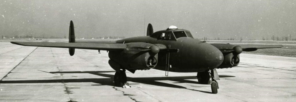
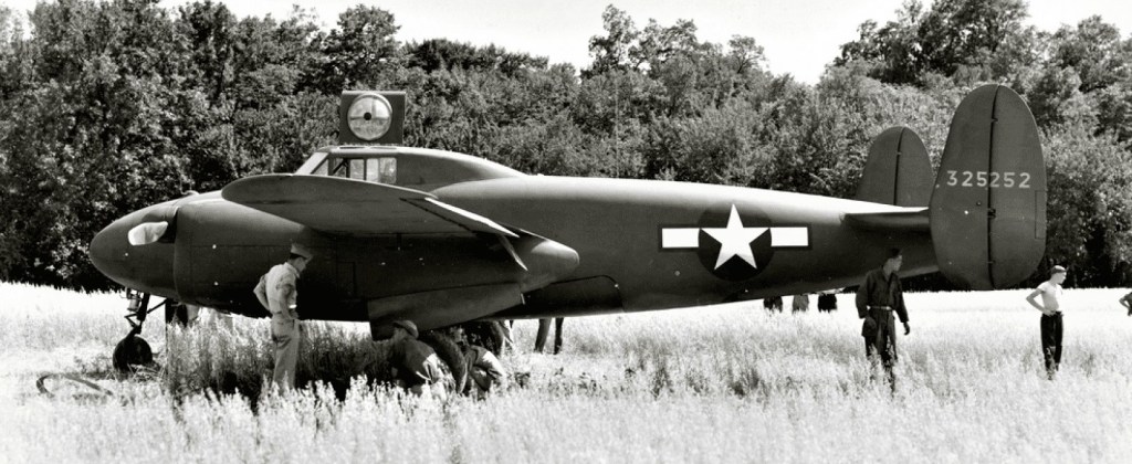
The Fairchild BQ-3, Model 79, was an early expendable unmanned aerial vehicle – referred to at the time as an “assault drone”. Development of the BQ-3 began in October, 1942, under a program for the development of “aerial torpedoes” that had been instigated in March of that year. Fairchild was awarded a contract for the construction of two XBQ-3 prototypes, based largely on the AT-21 Gunner advanced gunnery trainer already in United States Army Air Forces service.
XBQ-3 Serial # 43-25253
The XBQ-3 was a twin-engined, low-wing aircraft, fitted with retractable tricycle landing gear and a twin-finned empennage; although the aircraft was intended to be operated by radio control with television assist, a two-seat cockpit was included in the design for testing and ferry flights. Power was provided by two Ranger V-770 inline piston engines of 520 horsepower (390 kW) each; up to 4,000 pounds (1,800 kg) of explosives could be carried by the aircraft in unmanned configuration. The aircraft would be destroyed in the act of striking the target.
The first flight of the XBQ-3 took place in July 1944; later that month, one of the prototypes was severely damaged in a forced landing. Despite the accident, flight testing continued; however, the assault drone was determined to have no significant advantage over conventional bombers, and advances in the field of guided missiles were rapidly rendering the concept obsolete. As a result, the program was cancelled towards the end of 1944.
XBQ-3 Engines: 2 × Ranger V-770-15, 520 hp (390 kW) each Wingspan: 37 ft (11 m) Length: 52 ft 8 in (16.05 m) Height: 31 ft 1 in (9.47 m) Gross weight: 15,300 lb (6,940 kg) Maximum speed: 220 mph (350 km/h, 190 kn) Range: 1,500 mi (2,400 km, 1,300 nmi) 4,000 pounds (1,800 kg) warhead Crew: 1 (optional)
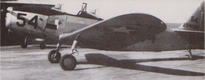
The Fairchild M-62 first flew in March 1939 and was used by the USAAF as a primary trainer. Between February 1940 and May 1944, some 8,000 aircraft were produced in the United States, Canada and Brazil.
M.62A
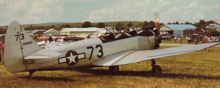
The PT-19 basic trainer was the military version of the M-62. The aeroplane was ordered in 1940 as the PT-19 with open cockpits and the 130.5-kW (175-hp) Ranger L-440-1 inline. These 270 aircraft proved to be only the beginning of a veritable flood, for next came 3,703 PT-19As with minor improvements and the 149-kW (200-hp) L-440-3 engine, and 917 PT-19B blind-flying trainers with a hooded front cockpit. Sales commenced in 1940 but so many orders resulted in licence production. Airframe production out-stripped engines and the Continental R-670 was substituted in 1942 resulting in the PT-23; the PT-23A was the blind-flying equivalent of which 261 were built.
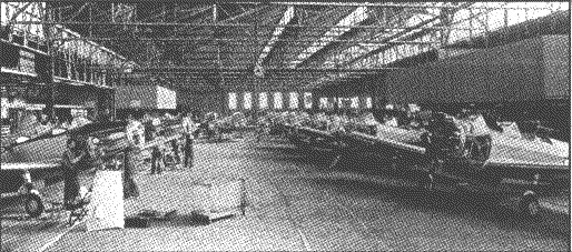
The St. Louis Aircraft Corporation built 44 Fairchild PT 19 and 306 PT 23. The Army gave St. Louis Aircraft production contracts for the Fairchild designed PT-19 trainer. During 1942-44, St. Louis Aircraft built and delivered 350 of these primary trainers, in two versions: the PT-19A, with a Ranger in-line engine, and PT-23/PT-23A, with a Continental radial. These trainers were all test-flown at St. Louis Aircraft’s own flying field, adjacent to the St. Louis Car factory on North Broadway in St. Louis.
Fairchild PT-19A (left) and PT-23A (right) trainers in St. Louis Aircraft factory, 1944
PT-19s were operated by Civilian Pilot Training schools throughout the war in conjunction with the Army Air Force, the principal user.
The RCAF adopted the PT-23 and PT-26 as the Cornell, built by Fleet Aircraft Ltd, Toronto. country Fleet Aircraft Company of Canada built 1642 Cornells under license, and they were designated either as PT-23s or PT-26s. The latter were distinguished by their cold-weather, enclosed canopy. The RCAF selected the Cornell as a successor to the Tiger Moth and Fleet Finch. The RCAF first flew Cornells in 1940 and retired the last one in 1947.
The more advanced PT-26 was fitted with an enclosed heated cockpit and IF instruments. 1,727 of this type were built in PT-26, PT-26A and PT-26B variants.
Two developments of the Fairchild M-62s appeared in the 1960s. One was the Funk F-23 built at Broken Arrow in Oklahoma and first flown in 1962, and the other was the Weatherly WM62C. An overall total of 7260 were eventually constructed by mid-1944.
Fairchild PT 19 A Cornell Engine : Ranger L-440-C5, 197 hp Length : 27.723 ft / 8.45 m Height : 7.612 ft / 2.32 m Wingspan : 35.991 ft / 10.97 m Wing area : 199.995 sqft / 18.58 sq.m Max take off weight : 2736.4 lbs / 1241.0 kg Weight empty : 2022.0 lbs / 917.0 kg Max. speed : 106 kts / 196 km/h Cruising speed : 88 kts / 163 km/h Service ceiling : 13205 ft / 4025 m Wing load : 13.74 lb/sq.ft / 67.00 kg/sq.m Range : 348 nm / 644 km
PT-23 Engine: Continental R-670-4, 220 hp.
PT-23A Engine: 1 x Continental R-670-4, -5 or-11, 164kW (240hp). Span: 10.97m (36ft ). Length: 7.9m (25ft 11 in) Max TO weight: 1111 kg (2,450 lb) Max speed: 128 mph at sea level. Operational range: 330 miles.