Fleetwings XBTK

In early 1942 the U.S. Navy’s Bureau of Aeronautics (BuAer) was planning the replacements for the Curtiss SB2C Helldiver dive bomber and the Grumman TBM Avenger torpedo bomber. The aircraft was to carry the torpedo in an internal bomb bay. By late 1943 it became obvious that the proposed VBT design like the Douglas SB2D had drastically increased in size and weight. Therefore the U.S. Navy was initiating a smaller dive bomber design. The BuAer recognized the engineering workload for the major wartime programs and therefore assigned the design to companies without a major wartime production. BuAer selected Fleetwings at Bristol, Pennsylvania (USA), which was acquired by Henry J. Kaiser in 1943.

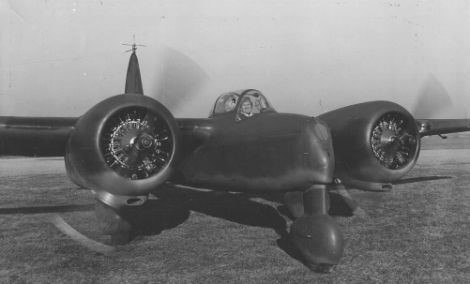
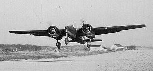
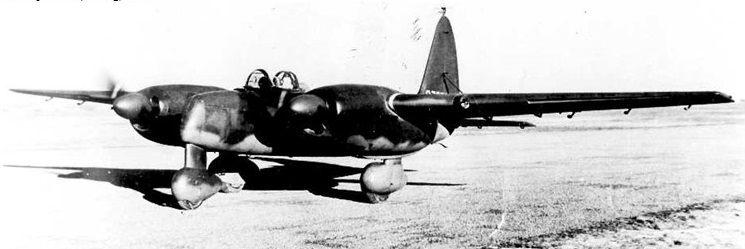
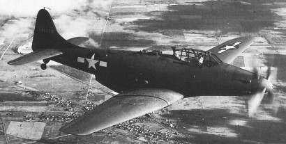
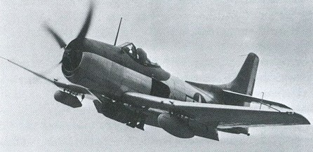
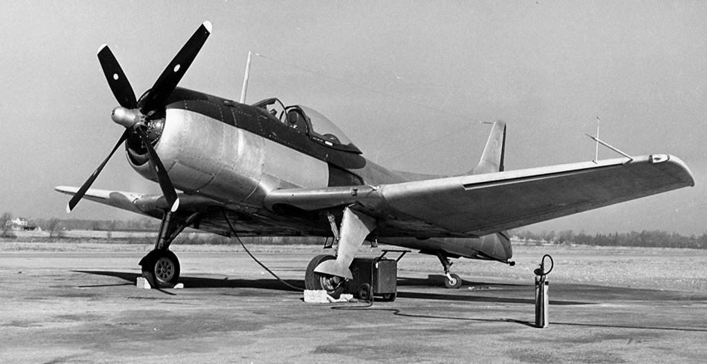
The XBK dive bomber program was initiated in February 1944 with a contract for two prototypes. To keep the airplane size down it was decided that all stores would be carried externally. A radar could be carried underneath the left wing. The dive brakes were of the lower and upper picket fence type at the inboard wing trailing edge. The horizontal tail was mounted on the tail fin above the fuselage. This feature should also avoid buffeting when the dive brakes were open. Unusual was the placement of the engine exhausts almost aft of the cockpit. It was hoped that this feature would significantly decrease drag.

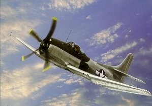
A mockup inspection without engine was already in April 1944. The engine was installed in May 1944 and the completion of the first prototype was scheduled for November 1944. To speed up later production the U.S. Navy even constructed a new airfield at the Fleetwing plant. In early 1945 BuAer requested that the plane would be able to carry a torpedo. The weapon was fitted to a new centreline station and the designation was changed to BTK. The first XBTK-1 was finally completed in March 1945, making its first flight in May 1945.

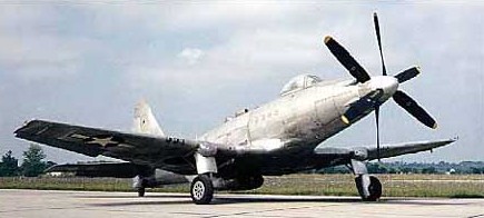
The flight testing revealed an inadequate engine cooling and a major fuselage vibration. These problems were corrected up to July 1945, and the R-2800-22W engine, which was already out of production, was replaced by the -34W. The flight testing continued at the U.S. Navy Naval Air Test Center at Naval Air Station Patuxent River, Maryland (USA), in August 1945. After the end of the Second World War the U.S. Navy cut orders to ten planes. The major redesign the NATC recommended was the use of a standard engine exhaust, as the cockpit temperature was very high and cockpit egress and access after an engine shutdown was extremely difficult. Also a new propeller should be installed. The plane was transported back to Fleetwings where redesign began. The second production aircraft first flew in March 1946 and featured built-in leading edge slots which greatly increased the stall performance of the aircraft. However, by early 1946 procurement of new planes was drastically cut down and the BTK found its role already filled by the Douglas AD Skyraider and Martin AM Mauler. In May 1946 it was decided to delay corrections of the design and complete five airframes already in production. Although a promising design, the U.S. Navy finally terminated the contract on 3 September 1946, as there was no need for the aircraft anymore. The five prototypes were scrapped.

Fleetwings XBQ-2

XBQ-2A

Development of the BQ-2 began on July 10, 1942, under a program for the development of “aerial torpedoes” – unmanned flying bombs – that had been instigated in March of that year. Fleetwings was contracted to build a single XBQ-2 assault drone, powered by two Lycoming XO-435 opposed piston engines, and fitted with a fixed landing gear in tricycle configuration; the landing gear was jettisonable for better aerodynamics.

XBQ-2A

Together with the XBQ-1, the USAAF also ordered a single XBQ-2. This was to be identical to the XBQ-1 except for Lycoming XO-435-3 engines and a jettisonable landing gear. The XBQ-2 was not built, however, being replaced by a single XBQ-2A. The XBQ-2A replaced the XO-435 engines by two Lycoming R-680-13 radial engines.

The BQ-2 was optionally piloted; a single-seat cockpit was installed for ferry and training flights; a fairing would replace the cockpit canopy on operational missions. The BQ-2 was intended to carry a 2,000 pounds (910 kg) warhead over a range of 1,717 miles (2,763 km) at 225 miles per hour (362 km/h); the aircraft would be destroyed in the act of striking the target. A single BQ-1 was to be constructed as well under the same contract.

XBQ-2A

Following trials of the television-based command guidance system using a PQ-12 target drone, the XBQ-2A flew in mid 1943; following flight trials, the design was determined to be too expensive for operational use, and the program was cancelled in December of that year. The aircraft was subsequently redesignated as ZXBQ-2A to denote its obsolescence.

XBQ-2A

Variants: Fleetwings BQ-1

XBQ-2A
Engines: 2 × Lycoming R-680-13, 280 hp (210 kW) each
Wingspan: 48 ft 7 in (14.81 m)
Gross weight: 7,700 lb (3,493 kg)
Crew: 1 (optional)
Warhead: 2,000 pounds (910 kg)

Fleetwings XBQ-1

XBQ-1

In March 1942, the USAAF initiated a program to develop radio-controlled assault drones, frequently called “aerial torpedoes” at that time. These aerial torpedoes were to be unmanned expendable aircraft (either purpose-built or converted from existing types), fitted with a large payload of high-explosive, remote-control equipment and a forward-looking TV camera. The drones were to be directed to the target by radio commands from a control aircraft, where the operator would “fly” the drone watching the video transmitted by the camera.

Development of the BQ-1 began on July 10, 1942. Fleetwings was contracted to build a single XBQ-1 assault drone, powered by two Franklin O-405-7 opposed piston engines, and fitted with a fixed landing gear in tricycle configuration. The aircraft was optionally piloted; a single-seat cockpit was installed for ferry and training flights; a fairing would replace the cockpit canopy on operational missions. The BQ-1 was intended to carry a 2,000 pounds (910 kg) warhead over a range of 1,717 miles (2,763 km) at 225 miles per hour (362 km/h); the aircraft would be destroyed in the act of striking the target. A single BQ-2 was to be constructed as well under the same contract.

Following trials of the television-based command guidance system using a PQ-12 target drone, and earlier trials of the XBQ-2A, the XBQ-1 flew in May 1944; however, the aircraft crashed on its maiden flight. Following the loss of the lone prototype BQ-1, the project was cancelled.

Variants: Fleetwings BQ-2

XBQ-1
Engine: 2 × Franklin O-405-7, 225 hp (168 kW) each
Wingspan: 48 ft 7 in (14.81 m)
Gross weight: 7,700 lb (3,493 kg)
Cruise speed: 225 mph (196 kn; 362 km/h)
Range: 1,717 mi (1,492 nmi; 2,763 km)
Crew: 1 (optional)
Warhead: 2,000 pounds (910 kg)

Fleetwings Division of Kaiser Cargo Inc

Fleetwings Division Of Kaiser Cargo Inc was formed 1929 and acquired Keystone Aircraft Corporation factory in 1934. Specialized in stainless-steel structure, including wings for the Douglas Dolphin and company’s own Sea Bird amphibian, the first stainless-steel aircraft to receive U.S. Approved Type Certificate. Wartime production included subcontract parts manufacture. Acquired by shipbuilder Henry J. Kaiser in March 1943 and developed Model 23 Tandem and Model 33 trainers. Designed XBTK-1 torpedo bomber in 1943; only three completed.

Fleet 60 Fort

The Fort was the first all-metal monoplane built by Fleet Aircraft of Canada (Fort Erie); and it was intended as a cheaper version of the Harvard, also an intermediate trainer.
The Fleet Fort Model 60K was designed and built by Canadians in World War II. The Fort’s maiden flight occurred in 1940.
Initially, the RCAF did not want to order the Model 60K, and their doubts proved valid. The Fort was relatively easy for pilot trainees to master, thereby making it unsuitable for transition to combat aircraft. The RCAF took 100 on strength in 1941. Also, the RCAF decided that pilots who had soloed in Finches and Tiger Moths could proceed to Harvards without training on Forts. The Forts were then used to train wireless operators until the last Model 60K was retired in 1946.

Fleet 60K Fort I
Engine : Jacobs R-915-7, 330 hp
Wing Span : 36ft (11m)
Length : 26ft 10in (8.18m)
Height : 8ft 3in (2.5m)
Speed : 162 Mph (260km/h)
Seats: 2

Fleet 7 Fawn / 8 / 9 / 10 / 11 / PT-6 / Fleet 16 Finch / CNIAR IAR-10

Fleet 7

The Fleet 7 flew first in 1930, a total of 374 were built, including the Fleet 10 designed for the European market.

Forty-eight of the Fleet Model 7 version with Kinner B-5 engine were built, plus several converted from Model 2 by Fleet in Canada.

Fleet 7A

The Fleet Model 7B was a Canadian production version, as were the Fleet Model 7C with Armstrong Siddeley Civet engine and Fleet Model 7G with de Havilland Gipsy III engine.

One Model 7 with 100-hp Kinner R-370-1 (Kinner K5) engine was acquired by the US Army Air Corps for service tests as XPT-6. Ten YPT-6 followed, similar to the XPT-6, used by the US Army Air Corps for service tests and evaluation. The YPT-6A was a modified version of the Model 7 fitted with an enlarged cockpit. Used by the US Army Air Corps for service tests and evaluation.

Fleet F.7C Trainer

The Fleet F.7C Trainer was built in 1937.

The Fleet Model 8 was a three-seat version similar to Model 7 (seven built), and Fleet Model 9 was a refined version of the Model 8 (12 built).

Fleet 8

The Fleet Model 10 was a refined version of the Model 7 for export to Europe, replaced the 1928-origin “looped” landing gear radius rod of the Models 2 & 7 for their left mainwheel with a center-hinged design for both mainwheels, using a V-form transverse cabane strut to provide the hinge-point.

The Model 10A version had a 100 hp Kinner engine, Model 10B with 125 hp Kinner engine, and Model 10D a 160 hp Kinner engine. The Model 10-32D was generally similar to the Model 10D, but with an increased 4-ft 0-in (1.22-m) wingspan.

The Fleet Model 10E version was powered with a 125 hp Warner engine and Model 10F with a 145 hp Warner engine.

The Fleet Model 10G was built for the governments of Portugal and Romania, with about 70 built in Romania by ICAR as Fleet-IAR 10, sometimes listed simply as IAR-10, all powered with a de Havilland Gypsy Major engine.

The Fleet Model 10H was powered with a Menasco C-4S engine, and Fleet Model 11 with a Kinner R-5 engine. Some Model 11 were exported to Argentina, China and Mexico.

The Fleet Model 16, or Fleet Finch, was a strengthened Canadian production version with sliding canopy, powered by a 130 hp de Havilland Gipsy Major engine, about 600 were built. The Fleet Model 16B, or Fleet Finch Mk II, was a strengthened Canadian production version, powered by a Kinner B5 engine. The Model 16D was similar to the Model 16B, but fitted with a Kinner B5 engine.

The Fleet Model 16R, or Fleet Finch Mk I, was the designation of the Fleet 16D built in Canada for the RCAF.

Finch 16B

The Fleet 16B Finch II is a progressive development of the original Consolidated Fleet primary trainer, manufacture of which was commenced in Canada by Fleet Aircraft in 1930. The Fleet Finch Model 16 was developed specifically for the RCAF. In 1938 Fleet Aricraft was exporting Model 10s, when the RCAF examined a 10D for possible use as a primary trainer. The Air Force needed an aeroplane that could perform aerobatics with full military equipment; therefore, numerous modifications were made, and the aircraft built for the RCAF were designated Model 16s. The first Finch 16B for the RCAF flew in March 1940.
The Fleet 16 first entered RCAF service with tandem open cockpits, but the severity of the Canadian winter necessitated the introduction of a sliding canopy at an early stage in the trainer’s service career.

The Fleet Model 16, or Fleet Finch, was a strengthened Canadian production version with sliding canopy, powered by a 130 hp de Havilland Gipsy Major engine, about 600 were built. The Fleet Model 16B, or Fleet Finch Mk II, was a strengthened Canadian production version, powered by a Kinner B5 engine. The Model 16D was similar to the Model 16B, but fitted with a Kinner B5 engine.

The Fleet Model 16R, or Fleet Finch Mk I, was the designation of the Fleet 16D built in Canada for the RCAF.

Fleet 16B

A total of 437 Fleet Finches were produced as Model 16s, the majority (430) for the RCAF. They were used as initial trainers in the BCATP at twelve EFTS’s across Canada in parallel with the Tiger Moth. They were replaced eventually by Fairchld PT-26 Cornells, and the last of the Model 16s stayed on RCAF inventory until 1947.

Fleet 16B

The Canadian manufacturing was a great success, with some 600 examples built for the Royal Canadian Air Force as the Fleet Fawn (Model 7) and Fleet Finch (Model 16).

United States manufacturing rights were eventually sold to Brewster Aeronautical Corporation, which intended to produce the Brewster B-1 based on the Canadian Model 16F prototype, built for Brewster.

Gallery

Fleet Model 7
Engine: Kinner B-5
48 built, plus several converted from Model 2 by Fleet in Canada

Fleet Model 7A
Engine: 125 hp Kinner B-5 or 100 hp Kinner K-5
Wingspan: 28 ft
Wing area: 194 sq.ft
Length: 21 ft 6 in
Height: 7 ft 11.5 in
Max speed: 115 mph
Cruise: 90 mph
ROC: 730 fpm
Ceiling: 16,000 ft

Fleet Model 7B

Fleet F.7C
Engine: Armstrong Siddeley Genet Major, 135 hp

Fleet Model 7G
Engine: de Havilland Gipsy III

XPT-6
One Model 7 for US Army Air Corps for service tests.
Engine: 100-hp Kinner R-370-1 (Kinner K5)

YPT-6
ten built

YPT-6A
Model 7 fitted with enlarged cockpit.

Fleet Model 8
seven built
Seats: 3

Fleet Model 9
12 built

Fleet Model 10

Fleet Model 10A
Engine: 100 hp Kinner

Fleet Model 10B
Engine: 125 hp Kinner

Fleet F 10 D
Engine: Kinner K 5 radial, 160 hp

Fleet Model 10-32D
increased 4-ft 0-in (1.22-m) wingspan

Fleet Model 10E
Engine: 125 hp Warner

Fleet Model 10F
Engine: 145 hp Warner

Fleet Model 10G
Engine: de Havilland Gypsy Major

Fleet Model 10H
Engine: Menasco C-4S

Fleet Model 11
Engine: Kinner R-5

Fleet Model 16 / Fleet Finch
Engine: 130 hp de Havilland Gipsy Major

Fleet 16B Finch Mk II
Engine: Kinner B-5 five cylinder radial, 125 hp
Maximum speed: 113 mph
Empty weight: 1,102 lb (500 kg)
Loaded weight: 1,860 lb (844 kg)
Span: 28 ft (8.5 m)
Length: 21 ft 8 in (6.6 m)
Height: 7 ft 9 in (2.4 m)
Wing area: 194 sq ft (18 sq m)
Seats: 2

Fleet Model 16D
Engine: Kinner B5

Fleet Model 16F
prototype for Brewster B-1

Fleet Model 16R / Fleet Finch Mk I
Fleet 16D built in Canada for the RCAF

Fleet Aircraft Inc

Reuben H.Fleet launched in 1923 in Buffalo, N.Y. the Consolidated Aircraft Co. Consolidated built flying boats for the U.S. Navy. The creation of the civil Model 14 “Husky”trainer led to the creation of the Fleet Aircraft Division in 1929.

Originally created as a means for Consolidated to enter the civil market, the company abandoned this ambition shortly before the completion of the first prototype. The manufacturing rights were purchased by the designer and Consolidated company president Reuben Fleet to put into production under his new enterprise, Fleet Aircraft. It was an immediate success, and in the first year of production alone, over 300 machines were sold. Consolidated quickly responded by buying Fleet Aircraft and retaining it as a subsidiary while opening a second production line at Fort Erie, Ontario, Canada.

Fleet produced the Fleet Model 2 with Kinner engine, and built a military two-seat primary trainer for the U.S. Army Air Service. Designated PT-6, it was an improved version of the PT series initiated by Consolidated Aircraft Corporation.

Manufacturing rights of the Fleet trainers were sold in 1939 to Brewster Aeronautical Corp.

Fleet Model 80 Canuck two-seat light-plane also built in quantity 1946- 1947, after which aircraft production ceased. In 1952 Fleet acquired type certificate for Super-V twin-engined Beech Bonanza conversion from Bay Aviation Services Co, Oakland, California.

Fisher XP-75 Eagle

XP-75

In February of 1942, the USAAF issued a Request For Proposals for a fighter/interceptor of high performance. Maximum speed was to be 440 mph at 2000 feet, operational ceiling was to be 38,000 feet, and range was to be 2500 miles. A special requirement was added for the initial climb rate, which was to be no less than 5600 feet per minute.

P-75A Eagle

In April of 1942, Donovan Berlin (who had been responsible for the P-36 and the P-40) left the Curtiss company to take over the directorship of the Aircraft Development Division of the Fisher Body Division of the General Motors Corporation. One of his first assignments was in response to the USAAF request. In September of 1942, Fisher submitted their proposal using the most powerful liquid-cooled engine then available, the 2,885-hp twenty-four cylinder Allison V-3420. This engine was basically a pair of coupled V-1710 engines, mounted side-by-side in a W-type configuration. Significant savings in cost and time were to be gained by employing major assemblies from existing aircraft already in production in the manufacture of the new interceptor.

Fisher XP-75 Eagle Article

The first of two proto¬type XP-75s that flew on 17 November 1943 was built with P-51 Mustang outer panels, F4U Corsair landing gear and A-24 Dauntless empennage.

On October 10, 1942, a contract for two prototypes was awarded to Fisher under the designation XP-75.

Serial numbers 43-46950 and 43-46951 were assigned to the two XP-75 prototypes. The Allison engine was to be located behind the cockpit and was to drive a set of contra-rotating propellers via an extension shaft and a reduction gearbox. The engine was cooled by a duct in the ventral fuselage. Initially, it was planned that the outer wing panels of the P-51 Mustang would be used in an inverted-gull configuration. However, at an early stage it was decided to drop the inverted gull-wing configuration and go with a straight wing design utilizing outer wing panels from a P-40.

By the summer of 1943, the USAAF had a more urgent need for long-range escort fighters than it did for fast-climbing interceptors. The urgent demand to exploit existing components was abruptly dropped. On July 6, 1943, the USAAF ordered six more prototypes that would be adapted to fulfill the long-range escort role. They were assigned the designation XP-75A, and the serial numbers were 44-32161/32166. They were to be powered by an Allison V-3420-23 engine, and were to be armed with six 0.50-inch machine guns in the wings and four 0.50-inch guns in the fuselage nose. At the same time, the USAAF decided to order 2500 production P-75As, although they did stipulate in the contract that if the production aircraft did not meet specifications the order might be cancelled. Maximum speed was to be 434 mph at 20,000 feet and 389 mph at sea level. These production P-75As were to be built at the Fisher plant in Cleveland, Ohio.

The first XP-75 flew on November 17, 1943. It was powered by an Allison V-3420-19 engine rated at 2600 hp for takeoff and driving a pair of contra rotating propellers. As planned, the wing was of a straight center section with P-40 outer panels with modified tips. The tail assembly was from an A-24, and the main undercarriage members were taken from an F4U Corsair.

The ‘hybrid’ test ships were fol¬lowed by six production XP-75As with bubble canopy rather than the braced hood of earlier machines and a modified tail assembly. The first of these flew on 15 Septem¬ber 1944 and had most compo¬nents designed new from the out¬set. It featured the V-3420-23 engine of the XP-75A.

All six XP-75A long-range escort versions were in the test program by the spring of 1944. Some problems were encountered with instability, since errors had been made in the initial estimate of the aircraft’s center of mass. The coupled Allison engine failed to give its full rated power. The engine cooling was inadequate, aileron forces were excessively high, and the spinning characteristics were poor. Though it could reach a speed of 400 mph, the XP-75 was disappointing in almost every other aspect.

At that stage in the war, the Republic P-47D Thunderbolt and the North American P-51D Mustang were more than adequately fulfilling the long-range escort role, and the USAAF decided that there was no longer any need for a new escort fighter.

Consequently, the USAAF decided to terminate the P-75 development program, and the production contract for the P-75A was cancelled on October 27, 1944. The serial numbers of the six P-75As built were 44-44549/44553.

By the time of contract termination, the first and second P-75A had been delivered to Elgin Field, Florida for tactical suitability trials, the third machine was in the shop being fitted with an experimental intercooler, and the fourth and fifth machines were almost complete.

Although the USAAF no longer had any need for the P-75, it was decided to go ahead and finish these machines and use them for development work. The sixth machine was to be placed in storage and scavenged for spare parts to keep the rest flying.
The five production P-75As never completed official performance trials, but enough testing was performed to confirm the fact that the maximum speed was at least 30 mph below that guaranteed by the manufacturer. The third machine received an experimental intercooler installation which permitted substantial increases in engine power.

The improved version was still unsatisfactory and after three Eagles had crashed, the entire program was cancelled on November 8, 1944. Only eight XP-75s and six P-75As were built.
The last production P-75A (serial number 44-44553) was on display in the Annex at the Wright-Patterson Air Force Base Museum in Dayton, Ohio, in 1992. This was apparently the aircraft that had been scavenged to keep the other P-75s flying, so more than a few things may be missing. The P-75A on display was loaned to the USAF Museum by the National Air and Space Museum of the Smithsonian Institution in 1977.

XP-75
Engine: Allison V-3420-23, 2885 hp
Span: 49 ft. 4 in.
Length: 40 ft. 5 in.
Height: 15 ft. 6 in.
Wing area: 347 sq.ft
Empty weight: 11,495 lb
Normal loaded weight: 13,807 lb
MTOW: 18,210 lb
Maximum speed: 404 mph.
Max speed: 433 mph at 20,000 ft
Cruising speed: 250 mph.
Range: 2,600 miles
Range max external fuel: 3500 miles
Service Ceiling: 29,500 ft.
Absolute ceiling: 36,400 ft.
Initial climb rate: 4200 fpm at 10,000 ft
Climb rate: 3900 fpm at 20,000 ft
Crew: One
Armament: six 0.50-inch machine guns wings (235 rpm) / four 0.50-in machine guns fuselage (300 rpm) / two 500-pound bombs