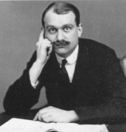
Handley Page

Frederick Handley Page
Age 27 (March 1913)

Born at Cranham Villa, Kings Road, Cheltenham, Gloucestershire, on November 15, 1885, Frederick Handley was the second son of Frederick Joseph Page and his Wife Arm Eliza, nee Handley. He always used the combination of “Handley Page”. A Cheltenham Grammar School report of 1896 placed him first in his class of 13 boys. He then studied electrical engineering at Finsbury Technical College, and in 1906 became chief designer for electrical machinery manufacturers Johnson & Phillips.

Handley Page Article

Already interested in mechanical flight, Frederick began experimenting with model gliders and ornithopters, eventually being invited to assist Maj R.F. Moore ,on the “Wings Committee” of the Aeronautical Society of Great Britain (ASGB).
In 1908 he was introduced to landscape artist Jose Weiss, who had patented a wing of distinctive shape, but Weiss was no engineer, so his gliders were rather crude. On June 10, 1908, FHP joined the Weiss Aeroplane & Launcher Syndicate.
While still at Johnson & Phillips he instituted some unauthorised aeronautical work using the factory track, but his employers took a dim view of this and dismissed him. Undeterred, FHP set up an office in a shed in Woolwich, even taking a stand at the Olympia Aero & Motor Boat Show in 1909, featuring the Weiss gliders and his own canard glider, of better construction but having the Weiss patent wing. He attempted to fly this from marshlands near Barking Creek, Dagenham, but without success. He was also manufacturing Weiss propellers and supplying small parts to budding aeronautical engineers and experimenters.

Frederick floated his new business as a private company on June 17, 1909, registering “Handley Page Ltd” for the express purpose of the design and manufacture of aircraft at Berking Creek, Essex. He always claimed that his was the first such company in the UK, but by this time Short Bros was well established as an aeroplane
manufacturer. However, Short Bros was a partnership, not a company.

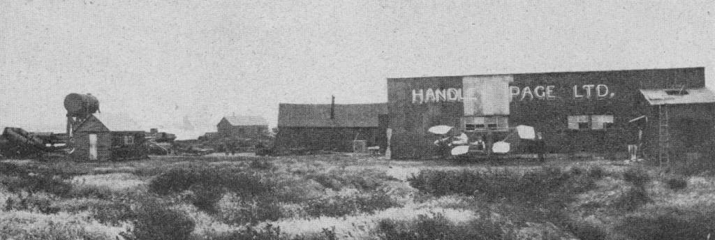
The first Handley Page factory were some wooden huts on the banks of the Thames at Barking, operating from 1909 to 1912. The company’s aerodrome was a playing field at Fairlop.

Handley Page factory 1911

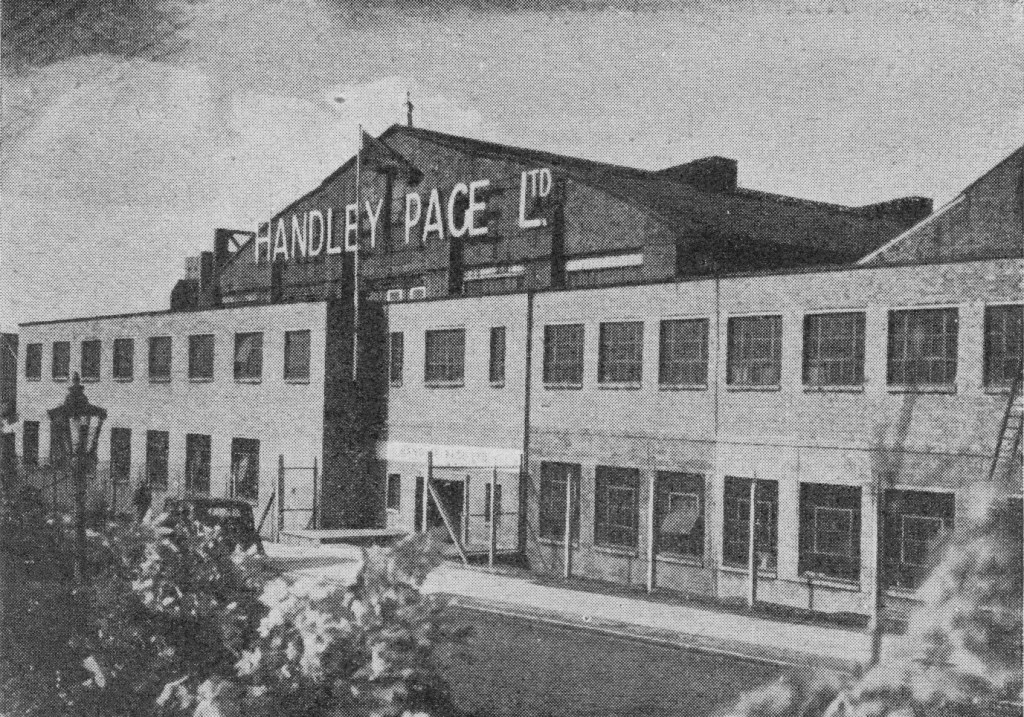
In September 1912, the H.P. works moved to 20,000 sq.ft of converted riding stables in Cricklewood, north London.

Handley Page Cricklewood 1949

From Cricklewood, final assembly and flying was done from Radlett.

Until the start of the First World War the young company built very few aircraft.

As soon as civil aviation was permitted after the war’s end, FHP formed his own airline, using converted O/400 bombers and flying to France and the Netherlands. It was taken over by Imperial Airways in 1924. He also exported six aircraft to China.
A big coup was his acquisition, using a company called the Aircraft Disposal Co Ltd, of some 10,000 government surplus military airframes, 30,000 engines and a huge amount of stores, in 1920.
At the end of World War One orders and military work ceased abruptly. FHP weathered the ensuing lean years remarkably well, with a minimal staff. Volkert and his assistant, S.T.A. Richards, produced an inspired series of designs comprising different fuselages combined with a standard set of biplane wings and tail. This was the “W” series of airliners and bombers, built throughout the decade. They also introduced air-cooled engines and metal structures.
24 October 1919 Patent No 157567 is issued for the HP slotted wing.

During the rearmament programme of the mid-1930s the company developed modern monoplane wings for its stopgap Harrow aircraft, and also started designing for dispersed production of components with final “flowline” assembly. The H.R 52 Hampden medium bomber continued this principle, and was the first H.R aircraft to have a retractable undercarriage. Two-thirds of the Hampdens produced were built by other firms.
Despite his strong and prescient urging for a change in bombing policy, from large bombers with heavy and draggy defensive armament to smaller unarmed bombers relying on high speed, Volkert designed the Halifax to an Air Ministry specification. Neither the span limitation of less than 100 ft nor the use of watercooled engines were to his liking, and only when Bristol Hercules engines and increased span were introduced in 1942-43 did the aircraft became competitive with the Avro Lancaster. Nevertheless, the “Halibag” proved capable of operation in all theatres, particularly the Far East. The parent firm built only 1,590 of the 6,177 produced, the rest being made in “shadow” factories.

Handley Page (Reading) Ltd was formed on 5 July 1948 to take over Miles Aircraft Ltd of Woodley for production of Marathon four-engined feederliner aircraft.

Handley Page (Reading) produced the aircraft as a navigational trainer for the RAF, and also as a short-haul airliner. The Reading-based company was also responsible for development of the HPR.3 Herald airliner, which flew initially with four piston engines in 1955, and was subsequently manufactured with two Rolls-Royce turbines as the Dart Herald.

January 1951

Sir Frederick died on April 21, 1962

The Handley Page company had completed the move of its headquarters from Cricklewood to its aerodrome at Radlett by 1966. It had facilities at Radlett and at Cricklewood for the manufacture and assembly of major components and the erection of complete aircraft. Total floor space available to the company was 971400 sq.ft and it employed some 4000 people.

Test facilities include a structural test rig for any specimen or structure up to 120 ft long by 70 ft wide and 26 ft high with a total applied load capacity of up to 400 tons; fatigue test equipment for 100 ton fluctuating load; water pressure tanks and a range of equipment for standard mechanical environmental, pneumatic and hydraulic tests, chemical and photoelastic analysis, metallography and radiography, and high- and low-speed wind tunnels. The aerodrome, which occupies more than 400 acres, has two paved runways, the longest being 6990 ft.

Directors of the Handley-Page company in 1966 were Air Chief Marshal Sir Walter Dawson, chairman; J. H. S. Green, managing director; C. F. Joy, chief designer; R. S. Stafford, technical director; G. C. D. Russell; S. L. Hastings; and E. Manley Walker. Senior executives are E. W. Pickston, general works manager; D. F Corbett, works manager at Radlett; K. Pratt chief engineer; E. P. Hessey, sales manager; J. Duthie, secretary; J. W. Allam, chief test pilot; and S. A. H. Scuffham, public relations manager.

The major sources of revenue of the company were aircraft sales, sub-contract manufacture, design and test facilities, aircraft overhaul, aviation equipment, domestic and industrial heating and ventilation equipment, food and chemical processing plant, and factory airconveyance installations. The factories were engaged on military contracts in connection with the conversion of Victor bombers, production and overhaul of the Herald, and the design and development of its new 8/18-seater HP137 Jetstream for which the first production line was being laid down in 1966. The company had sold 58 Heralds and was about to start production of more than 20 “off-the-drawing-board” Jetstream orders.

In 1966 feasibility and market studies revealed a definite market for a medium-sized turboprop mini-airliner for commuter and executive use. The H.P.137 Jetstrearn was launched, attracting nearly 200 orders and options in the first year. it even won the United States Air Force contest for the C- 10A transport. But it was a difficult aircraft for a firm used to large and expensive military designs, and development was prolonged. Its airworthiness category imposed a nominal limit in all-up weight which severely affected range/load performance. This was improved with the advent of higher-power engines and a change in category, which allowed take-off weight to rise to the level for which the Jetstream was designed. But it was too late. Development costs had risen to £13 million, and the backers pulled out; the company went into administration.

The death knell came on August 8,1969, when the company went into receivership. A reprieve seemed at hand when it was bought up by an American consortium, the K.R. Cravens Corporation, in January 1970 and rebranded Handley Page Aircraft Ltd. At the same time, however, the consortium’s head was diagnosed with terminal cancer and all foreign interests were dropped. By the end of February the company had ceased trading and on June 1, 1970, the name of Handley Page was consigned to history – after some six decades of aeronautical achievement.

Hamburger Flugzeugbau

Formed originally by Blohm und Voss in 1933. Aircraft production resumed 1956 with license manufacture of Nord Noratlas for Luftwaffe. Co-operated in license-production of Luftwaffe Lockheed F-104Gs and assisted with design work of Fokker F28 and Dornier Do 31E V/STOL project. HFB 320 Hansa Jet 6/11 -seat business jet first flew 1964.
Merged with Messerschmitt-Bolkow in 1969 to form MBB.

Hall Aluminium Co

USA
Founded 1927 to develop a prototype naval flying-boat based on the hull design of Britain’s Felixstowe F.5 for the U.S. Naval Aircraft Factory. The twin-engined Hall PH-1 was superseded by PH-2 and PH-3 variants which served in small numbers with the U.S. Coast Guard during the Second World War. In 1936 Hall flew the XP2H-1 four-engined patrol bomber, largest American-built flying-boat at that time.

Halford H1 / de Havilland Goblin / Allis-Chalmers J36

de Havilland Goblin

An offshoot of the Whittle design was the Frank Halford designed Halford H1. It was more powerful at around 2,300 lbs thrust but also larger and heavier. Design of the engine was carried out by Frank Halford at his London consulting firm starting in April 1941. It was based on the basic design pioneered by Frank Whittle, using a centrifugal compressor providing compressed air to sixteen individual flame cans with a straight through flow from the inlet at the front to the jet pipe, from which the exhaust powered a single-stage axial turbine. Compared to Whittle designs, the H-1 was “cleaned up” in that it used a single-sided compressor with the inlet at the front, and a “straight through” layout with the flame cans exhausting straight onto the turbine. Whittle’s designs used a “reverse flow” layout that piped the hot air back to the middle of the engine, in order to “fold” it and reduce its length. Halford’s changes made his engine somewhat simpler than Whittle’s designs, notably allowing one of the main bearings to be removed. Nevertheless it was a fairly compact design, even without the Whittle-style “folding”.

The H-1 first ran on 13 April 1942, and quickly matured to produce its full design thrust within two months. It first flew on 5 March 1943 in the Gloster Meteor DG206, and on 26 September in the de Havilland Vampire. The Goblin was the second British jet engine to fly, and the first to pass type tests and receive a “Gas Turbine” class type rating. It was around this time that de Havilland purchased Halford’s company and set him up as the chairman of the de Havilland Engine Company, with the engine name changing from H-1 to “Goblin”, while the new H-2 design became the “Ghost” – de Havilland jet and rocket engines were all named after spectral apparitions.

In July 1943, one of the two H-1s then available (actually the spare engine intended as a backup for the one installed in the Vampire prototype) was sent to the United States, where it was selected to become the primary engine of the Lockheed P-80 Shooting Star. This engine was fitted to the prototype which first flew on 9 January 1944. The engine was later accidentally destroyed in ground testing, and was replaced by the only remaining H-1 from the prototype Vampire. Allis-Chalmers was selected to produce the engine in the US as the J36, but ran into lengthy delays. Instead, the Allison J33, developed by a General Electric as the I-40 (their greatly improved 4,000 lbf (18 kN) version of the J31, itself based on Whittle’s W.1), was selected for the production P-80A.

“One example of the Allis-Chalmers licensed de Havilland Halford H-1 jet engine prototype was near Wichita Kansas in 2012. Ernst Nutsch had an Allis-Chalmers private museum in Washington Kansas. He had bought the jet engine at an auction in Iowa circa 1998. The condition was fair to good and it was on a repair stand. The Serial plate had Allis-Chalmers name on it as license from de Havilland, model of H-1, plus if I remember correctly it had a US Navy contract number.
The museum was sold off and Ernst passed away in 2010 however at the time the engine was not sold. The family still had it five years ago (in 2012).”
Alan Jones

Variants:

H.1/Goblin I
Developed about 2,300 lbf (10.2 kN) thrust (nominal thrust for prototype) and 2,700 lbf (12.0 kN) for production models.

Goblin II
3,100 lbf (13.8 kN)

Goblin 3
3,350 lbf (14.9 kN)

Goblin 35
3,500 lbf (15.6 kN)

Goblin 4
3,750 lbf (16.7 kN)

Allis-Chalmers J36
Licence production in the United States by Allis-Chalmers.

Aircraft applications:

de Havilland Vampire
de Havilland Swallow
Curtiss XF15C-1
Fiat G.80
Gloster Meteor
Lockheed XP-80
Saab 21R

Alternative applications:

Bluebird K4

Specifications :

D.H Goblin II D.Gn 27
Type: Turbojet
Length: 107 in (2,718 mm)
Diameter: 50 in (1,270 mm)
Dry weight: 1,550 lb (703 kg)
Compressor: Single sided, centrifugal flow
Combustors: 16 chambers
Turbine: Single stage axial flow
Fuel type: Kerosene (R.D.E. / F / KER)
Oil system: metered pressure spray at 50 psi (344.7 kPa) dry sump, 40 S.U. secs (13 cs) (Intavia 620) grade oil
Maximum thrust: 3,000 lbf (13.34 kN) at 10,200 rpm at sea level
Overall pressure ratio: 3.3:1
Turbine inlet temperature: 1,472 °F (800 °C)
Fuel consumption: 3,720 lb/hr (465 imp.gal/hr), (1,687 kg/hr) or (2,114 l/hr)
Specific fuel consumption: 1.18 lb/lbf/hr (120.285 kg/kW/hr)
Thrust-to-weight ratio: 1.9 lbf/lb (0.0186 kN/kg)

Hafner Rotachute

Rotachute Mk.V

By 1940, Hafner had taken charge of the rotorcraft team established at the Airborne Forces Experimental Establishment at Ringway, Manchester, and the idea of using a rotor instead of a parachute as a more accurate means of landing personnel in enemy territory was developed. Work on what was to become known as the Rotachute began on October 3, 1940, and practical tests began only eight days later with 3 ft (0.91 m) diameter balsa and spruce rotor blades attached to lead ballast weights. Preliminary drops from a Whitley showed that these models were not strong enough but also demonstrated that a properly ballasted rotor could achieve stable flight.
The Rotachute consisted of a soldered steel tube framework, carrying the rotor and having its rear part covered with rubberized fabric in which there were two small vertical shutters.
The rotor had two wooden blades articulating on the hub by means of steel hinges. The hub was attached to a small upright component by a rubber block acting as a universal joint, so that some vertical displacement could occur but vibrations were not transmitted to the main structure.
The rotor controls operated in the opposite way from those on an aircraft. To raise the nose, the control column was pushed forward; to bank to the right, the column was moved to the left.
The undercarriage originally consisted of two main wheels joined by an axle and placed almost directly below the rotor. Following towing tests behind a car, changes were made and in the Mark 2 a skid was added.
A new model, called M.3, was constructed with greater length, a rigid tail, and two metal blades with a total weight of 5 lb (2.26 kg). Launches from a Whitley on October 16, 1940 and from the interplane struts of a Tiger Moth on November 7th were only partially successful, but on November 1 5th a completely successful descent was made from the Tiger Moth, and the first important milestone was passed in the development of the Rotachute as a substitute for an ordinary parachute. Further successful descents were made, from the Tiger Moth and from an Avro 504, during November and December.
The next step was to build a larger model, the M.10, with a diameter of 10 ft (3.05 m) and weight of 100 lb (45.3 kg). After stability tests on the ground on February 19, 1942, this model was mounted on a special outrigger structure and launching gear attached to the interplane struts of a Boulton Paul Overstrand bomber and the first successful launch was made over Tatton Park, near Manchester, on March 14th. The model descended from 2,000 ft (609.6 m) at 1,500 ft/min (7.6 m/sec.).
While the model tests were proceeding, Hafner had been busy designing the full scale Rotachute, the preliminary layout drawing for which was dated November 16, 1940. The design was known as the H.8, and the idea at this stage was to use the Rotachutes in conjunction with a specially constructed or modified troop ¬carrying aircraft, in which they would be carried in a row on a rail running along the top of the cabin The launching gear was to be in the tail and it was hoped to achieve a launching rate of one every fifteen seconds. By adjusting their angle of glide ¬which would be in the same direction as the flight of the launching aircraft, the Rotachutes would join up to land in a tight for¬mation or such, at least was the theory.
The Rotachute comprised, basically, a steel tube frame to seat the pilot, a two blade rotor with freely flapping blades and a rubber ¬mounted skid. The rotor hub was also rubber mounted, this mounting combining the functions of a control hinge with that of a damper for vertical as well as horizontal vibrations. The fuse¬lage framework was open at the front but had a tapered fairing behind the pilot to, provide stability in the yaw and pitch axes. This fairing was to be made entirely of rubberised fabric, with no framework, and was to be inflated to maintain the required shape, a feature selected to minimise the stowage space in the launching aircraft
Control was obtained by means of a hanging stick directly attached to the rotor hub. Movement of the stick tilted the entire hub and rotor. No means of yaw control were provided, turns being made simply by banking by means of a rotor tilt to left or right.
As designed in 1940, the Rotachute had a structure weight of 50 lb (22.7 kg) and could carry a useful load of about 240 lb (109 kg) comprising a pilot and parachute plus a Bren gun Mk.1 with 300 rounds. The rotor had a diameter of 15 ft (4.57 m). At the time of the trials, it was the smallest man carrying vehicle capable of controlled flight to have been built.
Contracts for the construction of prototype Rotachutes were placed by the. Ministry of Aircraft Production with F. Hills and Sons of Manchester and the Air¬work General Trading Company of Hounslow. Both companies subcontracted the production of a number of specialised components. Before flight trials began a full scale rotor was tested at the A.F.E.E. mounted on the back of a modified Ford truck. Racing up and down the runway at Ringway, this test rig provided photographic and other records on the performance of the rotor. The same lorry was then modified to carry the complete Rotachute, attached to a pylon by means of a flexible linkage which permitted 6 inches (15. 2 cm) of vertical and lateral movement, and 6 degrees of rotation about the centre of gravity in any direction. A number of runs was made with a pilot in the Rotachute, which provided preliminary information on the handling and control characteristics.
Early in 1942, enough progress had been made for the first tentative flights to take place. Throughout the development programme the policy was one of taking small steps at a time, and for the first flights, it was decided to tow the machine behind a 28 hp Humber car. Since the Rotachute had no wheeled under-carriage, a two wheeled truck was used, to which the aircraft was lightly attached. As soon as flying speed was obtained, the pilot released the restraining cable, remaining directly attached to the towing car.
Two trial runs at Ringway, on February 2 and 16, 1942 ended in heavy landings in which the Rotachute overturned and the blades were broken. A third run, using the 6,000 ft (1 829 m) runway at Snaith on February 24th, was little better and it was concluded that, at least for training purposes, a three point undercarriage would be needed, and that more tail fin area was required for directional stability.
These modifications produced the Rotachute Mk. II, with two small wheels carried on an axle below the centre of gravity (the forward end of the landing skid provided the third point of contact). The original rear fuselage fairing, as already described, comprised a rubber fabric bag with air scoops to maintain inflation during flight. With the need to lengthen this fairing, the frameless construction was no longer acceptable because the flexible bag might foul the rotor. Therefore the Rotachute Mk.II had a single wooden member running round the profile of the tail fin, with vertical members interspaced and covered with rubber fabric. The tailplane was wholly flexible and the entire fairing inflated through ram effect with forward speed.
Concurrently with this modification, a more conventional light wooden framework, fabric covered, was designed as an alter¬native and this was used for the Rotachute Mk. III.
The Rotachute II was first flown on May 29, 1942, towed by a Jeep. It was in free flight for only 15 seconds but made a successful landing. Five more flights were made on May 31 and three on June 1, each of two to three minutes duration. This concluded work with the Mk.II, and all efforts then became concentrated on the Mk.III. By this time, interest in the Rotachute as a substitute for a parachute had waned, but the possibility of using rotors to ferry supplies, including vehicles and tanks, from air to ground was of interest in official circles. Two Specifications were issued to cover the work in hand at the A.F.E.E. 10/42 for Hafner’s proposed Rotabuggy and 11/42 for his Rotachutes.
Towed tests with the Rotachute III began at Ringway on June 2, 1942, with two flights of four minutes each. These and several subsequent flights ended with controlled landings while still on tow, the first free landing being made successfully on June 9.
In all seventeen ground towed flights were made by the Mk. III, in which heights of up to 100 ft (30.5 m) were reached. The average take off run was 300 ft (91.4 m), the minimum take off speed was 28 mph (45 kph) and the landing run, depending on wind force, was from zero to 50 ft (15.2 m).
Proceeding to the next stage, a Tiger Moth was chosen for the initial airborne tow tests. This aircraft had already been equipped for glider towing. A 300 ft (91.4 m) cable was used, with the pilot in the rear cockpit and an observer facing rearwards in the front cockpit. On June 15th, a taxi run was made behind the Tiger Moth and then came two two minute flights on June 17th in which the Rotachute, but not the tug, became airborne. Two later flights on June 17th behind the Tiger Moth ended in releases and free landings.
In this series of trials the Rotachute III made fourteen free flights in all from Tiger Moth tows, the last being made on August 18, 1942. In the course of these flights, the machine reached a maximum height of 3,900 ft (1189 m), released at a maximum of 3,700 ft (1128 m), recorded a top speed of 93 mph (150 kph), and made one flight of 40 minutes duration. Total flight time on these fourteen sorties was 3 hr 10 min. Subsequently, numerous flights were made for pilot training, using a Jeep as the tug.
Later work with the Rotachute was concerned with development of the rotor for the Rotabuggy, and improvement of the handling characteristics, particularly a tendency to fall into slow speed turns at low speeds. The Rotabuggy was to use a rotor with fixed coning angle and two flights were made with a rotor of this type on the Rotachute III, on September 21 and 25, 1942, towed first by a Jeep and then by the Tiger Moth. For the next few months, the Mk. III was used for some test and performance flights, towed by the Tiger Moth or a Jeep. Flying at a weight of 295 lb (134 kg), the minimum rate of descent was found to be 960 ft/min (4.9 m/sec.), rather higher than had been hoped.
To increase directional stability, small fins were added at the end of the tailplane, and the modified machine became the Rotachute IV, first flown behind a Tiger Moth on April 29, 1943. Adjustable trimming tabs were later added to the fins, to reduce a tendency to yaw to port and these were first flown on May 20, 1943. On September 7, 1943, a single flight was made behind the AFEE’s Avro Tutor and then on October 18, 1943, the Tiger Moth made the last aerial tow of a Rotachute.
In the final analysis, the Rotachute had been found to be a comparatively simple machine to fly and easy to land in a very restricted area. Its drag proved to be larger than expected but overall performance was satisfactory. The operational need for which the Rotachute had originally been conceived did not materialize but from this work by Hafner and his team at the AFEE derived a great deal of today’s knowledge of light rotorcraft. One of the Rotachutes was shipped to the USA during the war.

Rotachute
Number of seats: 1
Rotor diameter: 4.57m
Height: 2.08m
Weight fully loaded: 134kg
Empty weight: 34kg
Cruising speed: 136km/h

Guiberson A-980 / A-1020

Guiberson T-1020

The Guiberson A-1020 (ATC 220) is a four-stroke diesel radial engine developed by for use in aircraft and tanks.
Development started in the 1930s with the A-918 designed by C C Spangenberger and A-980 designed by Fred A. Thaheld, which was first flown in 1931. It is a single-row direct drive nine cylinder-four cycle engine. Four A-918 were built.

Production A-1020’s and T-1020’s were designed and sold by Guiberson and produced by Buda Engine Co.

A T-1020 version was coincidentally produced for use in tanks. To demonstrate its capability to military and civil aviation officials in 1940, a 1500-mile flight from Dallas to Washington DC took 10h:35m flying time at an average 142mph. Cruising at 3000′ altitude at 1800rpm on Caterpillar tractor fuel (6 cents a gallon) consumed at the rate of 11.5 gph, cost was only $6.90. Three gallons of lubricating oil added $4.20—a total of $11.10 for fuel and oil for the flight. Its fuel cost of less than 12 cents a mile was an unheard-of figure for flight operations at the time.

Variants:

Guiberson A-980
210hp – the initial development model for use on aircraft.

Guiberson A-1020
340hp – production engines for aircraft use.

Guiberson T-1020
250hp for use in light tanks such as the M5 Stuart

Applications:
Waco 10 – A-980
Stinson Reliant – A-1020
M5 Stuart light tank – T-1020

Specifications:

A-918
1934
250hp

A-980
1932
ATC 79
185hp

A-1020
Type: 9-cyl air-cooled radial diesel piston engine
Bore: 5.125 in (130.18 mm)
Stroke: 5.5 in (139.70 mm)
Displacement: 1,021 cu in (16.73 l)
Dry weight: 650 lb (294.84 kg)
Designer: F. A. Thaheld
Power output: 340 hp (253.54 kW)
Compression ratio: 15:1
Specific fuel consumption: .42 lb/hp/hr (0.14 kg/kW/hr)
Oil consumption: 0.33 US gall/hr (1.25 l/hr
Power-to-weight ratio: 0.52 hp/lb (0.85 kW/kg)

Gudkov GU-1

The Gu-1 single-seat fighter designed by Mikhail Gudkov had a liquid-cooled engine installed aft of the pilot’s cockpit, close to the CG, and driving the propeller via an extension shaft and reduction gear. Design of the Gu-1 was commenced in 1940, and the fighter was of mixed construction, with welded steel-tube forward and centre fuselage covered by duralumin skinning and metal wing mainspars, the remainder of the airframe being of wood. Power was provided by a Mikulin AM-41 12-cylinder liquid-cooled engine, the main coolant radiators for which were buried in the wings. The Mikulin bureau experienced difficulties with the extension shaft and reduction gear which were not ready for testing until 1942. Armament comprised a single 37-mm Taubin cannon firing through the propeller shaft. In the event, the Gu-1 proved to be seriously overweight.

The initial flight test was performed by A I Nikashin on 12 July 1943, but after reaching some 650 ft (200 m), the fighter dived into the ground, killing the pilot, and further development of the Gu-1 was abandoned. No illustrations of the Gu-1 appear to have survived and the only available data are the weights.

Engine: Mikulin AM-41 12-cylinder liquid-cooled
Empty weight, 8,249 lb (3 742 kg).
Loaded weight, 10, 163 lb (4610 kg).
Armament: 1 x 37-mm Taubin cannon

Gudkov

Mikhail Ivanovich Gudkov, who had been with the Lavochkin OKB before the team Lavochkin, Gorbunov and Gudkov (of LaGG fame) split up, had his doubts about the objectivity of the then deputy People’s Com¬missar for scientific research and experimental construction in the field of aviation, Alexandr Sergeyevich Yakovlev. He put his design on Stalin’s personal desk and hoped for the best. Stalin called Yakovlev in and asked what he thought of the design and ordered Yakovlev to go ahead with it, saying: “We’ll risk the millions and I’ll take the blame if necessary.” Yakovlev couldn’t very well back down and the Gu 1 was built. Gudkov never designed another plane.