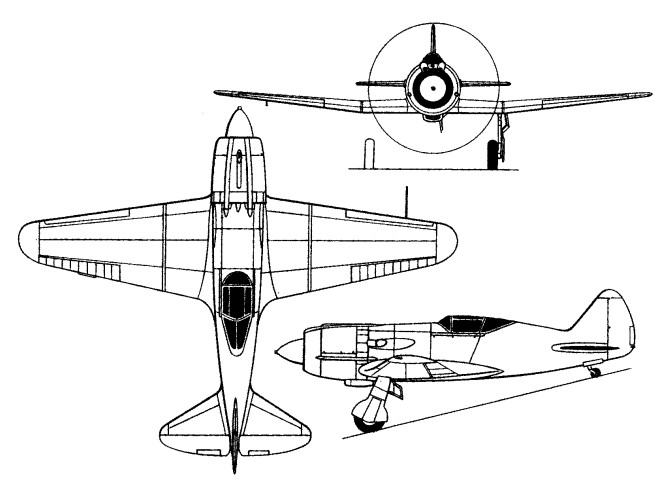
Late in 1941, series production of the MiG-3 was being phased out. The AM-35A engine manufacture was being discontinued as priority having been assigned to the AM-38 for the IL-2 Shturmovik. An attempt was made to adapt the basic airframe to take the 1700hp Shvetsov M-82A 14-cylinder air-cooled radial.
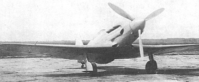
Assigned the Izdeliye designation IKh by the OKB and the provisional official designation I-210, and also referred to unofficially as the MiG-3M-82, the first of five airframes adapted to take the new engine was flown in December 1941.
The M-82A weighed only 20kg more than the AM-35A that it supplanted, but was 38cm wider, a new forward fuselage being necessary to cater for the cross section translation from the circular cowling to the oval centre fuselage. The armament consisted of three 12.7mm guns.
Plans were prepared to initiate IKh production as the MiG-9, but flight test revealed a serious drag problem, severe tail vibration and poor control characteristics. Despite the disappointing results of factory testing, the first aircraft was fitted with yet two more 7.62mm guns and sent to the Kalinin Front. The TsAGI, meanwhile, conducted full-scale wind tunnel testing with one of the IKh aircraft, resulting in development of the I-211.
Engine: 1700hp Shvetsov M-82A 14-cylinder air-cooled radial Take-off weight: 3382 kg / 7456 lb Empty weight: 2720 kg / 5997 lb Wingspan: 10.20 m / 33 ft 6 in Length: 8.08 m / 26 ft 6 in Wing area: 17.44 sq.m / 187.72 sq ft Max. speed: 565 km/h / 351 mph Range: 1070 km / 665 miles
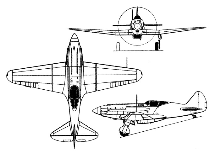
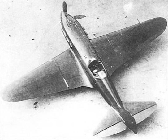
With the primary objective of improving the aerodynamics of the basic MiG-3 design, the OKB began work late in 1941 on an enhanced version of the fighter to which it gave the Izdeliye designation of D. Known officially as the I-230, and later as the MiG-3U – the suffix letter signifying uluchshenyi (improved) – the new fighter was first flown in August 1942.
Whereas the fuselage of the MiG-3 was primarily of steel tube with duralumin skinning, that of the I-230 was almost entirely of wood owing to the contemporary metal shortages. By comparison with the MiG-3, the fuselage was lengthened by 37cm, but the Mikulin AM-35A engine was retained and the wing of the first prototype was unchanged, armament consisting of two 20mm SP-20 (ShVAK) cannon mounted above the engine.
The second prototype differed in having a larger wing of 18.00sq.m area and spanning 11.00m. Performance proved good during factory and state trials, but it was not possible to reinstate production of the AM-35A and production of the I-230 was therefore restricted to a pre-series of five aircraft which were assigned to a Guards Regiment (1 GvIAP) on the Kalinin front for service evaluation.
Prototype 1 Engine: Mikulin AM-35A, 1200 hp Wingspan: 10.20 m / 33 ft 6 in Length: 8.62 m / 28 ft 3 in Wing area: 17.44 sq.m / 187.72 sq ft Max take-off weight: 3285 kg / 7242 lb Empty weight: 2612 kg / 5759 lb Max. speed: 660 km/h / 410 mph Range: 1350 km / 839 miles
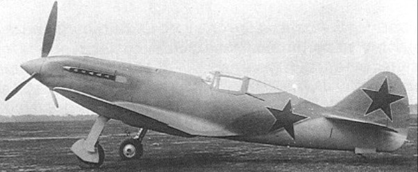
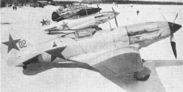
Lacking the time for a redesign of the MiG-1 to eradicate the fighter’s less acceptable characteristics, a series of ‘fixes’ were applied to the basic design to result in the MiG-3. Power plant and (initially) armament remained unchanged, but some structural simplification and strengthening was introduced. The engine was moved forward 10cm and dihedral of the outer wing panels was increased by one degree. A 250 lt supplementary fuel tank was introduced beneath the pilot’s seat, the aft fuselage decking was cut down, and the radiator bath fairing was enlarged and extended forward. The supercharger intakes were revised; 9mm seat armour was provided, together with radio, and four wing hardpoints were introduced for a maximum external load of 220kg.
The first MiG-3 left the factory in December 1940, 11 being completed by the end of the month. 140 were produced in January 1941, and, by June, production had peaked at 25 aircraft every 24 hours. The first MiG-3 was delivered to a VVS regiment in April 1941, simultaneously with the MiG-1, and production continued until 23 December 1941 with approximately 3,120 built, but 50 more were completed from component stocks in the early summer of 1942.
Some MiG-3s had a supplementary pair of 12.7mm BK machine guns under the wings, raising take-off weight to 3510kg, and others were fitted with two 12.7mm UBK guns in the wings.
Tests were also performed with two fuselage-mounted 20mm ShVAK cannon.
Engine: Mikulin AM-35A, 1200 hp. Wingspan: 10.20 m / 33 ft 6 in Length: 8.25 m / 27 ft 1 in Height: 2.65 m / 8 ft 8 in Wing area: 17.44 sq.m / 187.72 sq ft Max take-off weight: 3350 kg / 7386 lb Empty weight: 2699 kg / 5950 lb Max. speed: 360 mph Range: 820 km / 510 miles Armament: 2 x 50 mg, 2 x .30 mg
The first design to achieve production status of an OKB (Experimental Construction Bureau) headed by Artem I Mikoyan and Mikhail Y Gurevich, the MiG-1 was conceived as a high-altitude interceptor under the OKB’s Izdeliye (Product) designation Kh.
Also assigned the initial military designation I-200, the first of three prototypes was flown on 5 April 1940, attaining 648.5km/h at 6900m on the following 24 May. Second and third prototypes flew on 9 May and 6 June 1940 respectively, factory and state testing being performed in parallel, with the factory testing completed on 25 August and the state testing on 12 September 1940.
The MiG-1 was powered by a 1350hp Mikulin AM-35A and carried an armament of one 12.7mm UBS and two 7.62mm ShKAS guns. Manoeuvrability and handling were considered inadequate, longitudinal stability and control responses were poor, and a programme of peripheral redesign paralleled manufacture of an initial batch of 100 aircraft, the last of which was completed in December 1940. The first eight MiG-1s had non-jettisonable side-hinged cockpit canopies, the remainder having jettisonable aft-sliding canopies.
The first MiG-1 was delivered to a VVS regiment in April 1941, by which time this fighter had been supplanted in production by the MiG-3.
MiG-1 Engine: 1350hp Mikulin AM-35A Max take-off weight: 3099 kg / 6832 lb Empty weight: 2602 kg / 5736 lb Wingspan: 10.20 m / 33 ft 6 in Length: 8.16 m / 26 ft 9 in Height: 2.62 m / 8 ft 7 in Wing area: 17.44 sq.m / 187.72 sq ft Max. speed: 628 km/h / 390 mph Range: 580 km / 360 miles
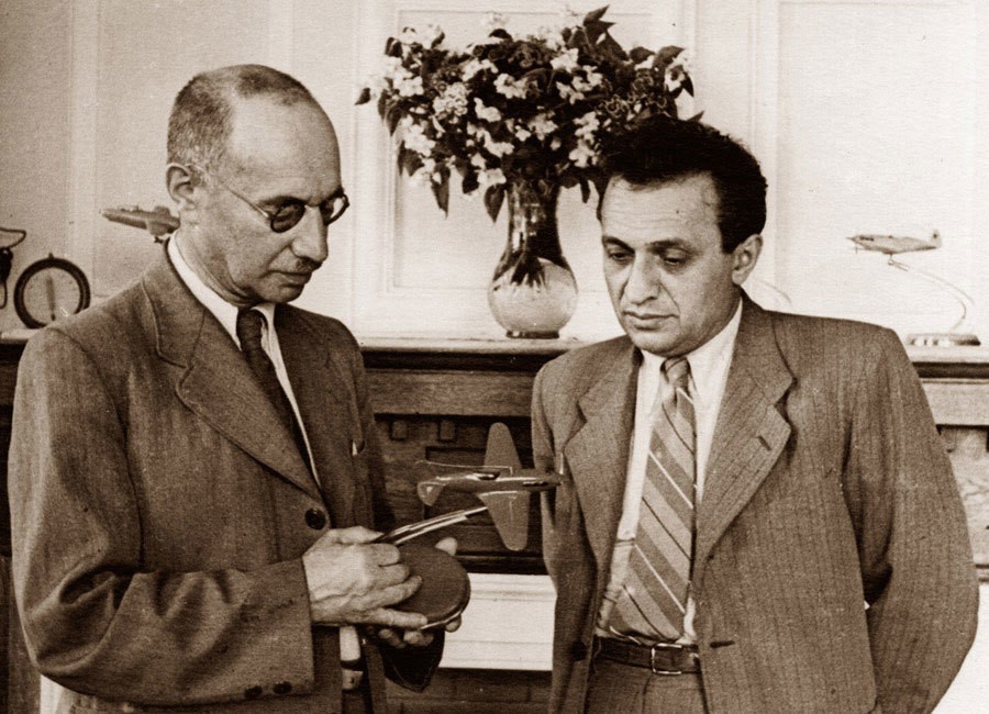
Mikhail Iosifovich Gurevich and Artem Ivanovich Mikoyan with a model of the MiG-3 fighter
A. Mikoyan and G. Gurevich design bureau established December 1939; still operating in 1990 as MAPO “MiG” as part of MIG “MAPO-M” organization, although Gurevich retired in early 1960s and Mikoyan died December 9,1970.
MiG-1 fighters with AM-35 engine produced 1940-1941; developed MiG-3 produced until 1942. First jet aircraft built in quantity was MiG-9 with twin RD-20 (BMW 003A) engines, flown 24 April 1946. Swept-wing MiG-15 with Russian copy of Rolls-Royce Nene introduced 1947, built under license in Czechoslovakia and Poland. Followed by approximately 9,000 of derived MiG-17, with redesigned wing, manufactured 1950-1957. Twin Mikulin AM-5-powered MiG-19 flown September 1953, built under license in Czechoslovakia, Poland, and China. Superseded by delta-winged MiG-21, in service in the USSR from 1959 and, when built in India, was first Russian aircraft manufactured in non-communist country.
Col-Gen Mikoyan died in 1970.
As ANPK “MiG” named after A.I. Mikoyan Aviation Scientific- Production Complex, produced MiG-23 (4,278 constructed 1969-1985; also built in India) and MiG-27 (over 900 between 1973 and 1983) related variable-geometry fighter and ground-attack aircraft, MiG-25 Mach 2.8+ reconnaissance aircraft and interceptor (some 1,200 built up to 1985), and MiG-31 long-range interceptor (about 400, operational from 1983).
MAPO ‘MiG’ produced MiG-21 upgrade as MiG-21 -93, MiG-29 Fulcrum lightweight close-air-combat fighter (first flown October 1977 and over 1,500 built, serving since 1983), improved MiG-29M (first flown April 1986) and MiG-33 export version, MiG-29K shipborne fighter prototype (first flown July 1988, first landing on aircraft carrier Admiral KuznetsovNovember 1989, and development restarted in 1996 after earlier program halt), MiG-35 multirole fighter (first flight 1999?), MiG 1-44 uniquely configured newgeneration combat aircraft (first seen February 1999), and MiG-AT/UTS/AC series of advanced and combat trainers. MiG-301/321 are reported hypersonic reconnaissance aircraft, thought to be under development. Also developing MiG-110 light multipurpose transport and MiG-115 and MiG-125 transports.
Migavia – the first national aircraft manufacturer in Russia aircraft corporations. RAC “MiG” is integrated company in which all technologies of design, production and improvement of aircraft are collected together in one legal frame. Corporation Migavia holds the shares of other corporations which are included into the complex of firms developing and producing the aircraft engines.
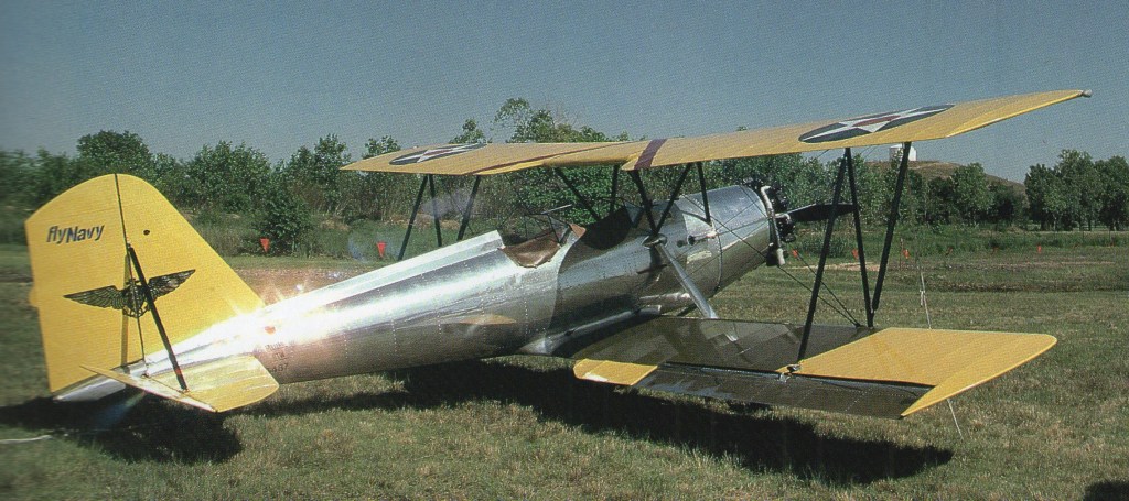
Meyers developed the OTW-160 biplane trainer and MEW-165W monoplane trainer for U.S. schools within CAA War Training scheme. The OTW featured an all metal fuselage mated with fabric-covered wings and horizontal stabiliser. A total of 102 were built.
Formed 1936 at Tecumseh, Michigan. Developed OTW- 160 biplane trainer and MEW-165W monoplane trainer for U.S. schools within CAA War Training scheme. Postwar production included MAC 125 and MAC 145 two-seat cabin monoplanes with Continental engines. Meyers 200 four-seat cabin monoplane flown 8 September 1953, deliveries began 1959. Acquired by Rockwell-Standard Corporation 12 July 1965, and marketed Model 200 as Aero Commander 200. Manufacturing rights in this model were acquired in 1977 by Meyers Aircraft Manufacturing Company of Broomfield, Colorado, to build the Meyers 200D. 1980: Meyer Aircraft, 576 Abby Dr, Corpus Christi, TX 78413, USA.
Alan Arnold Griffith published a seminal paper in 1926, An Aerodynamic Theory of Turbine Design, that for the first time clearly demonstrated that a gas turbine could be used as a practical, and even desirable, aircraft powerplant. The paper started by demonstrating that existing axial compressor designs were “flying stalled” due to their use of flat blades, and that dramatic improvements could be made by using aerofoil designs instead, improvements that made a gas turbine practical. It went on to outline a complete compressor and turbine design, using the extra exhaust power to drive a second turbine that would power a propeller. In today’s terminology the design was a turboprop. In order to prove the design, Griffith and several other engineers at the Royal Aircraft Establishment built a testbed example of the compressor in 1928 known as Anne, the machinery being built for them by Fraser and Chalmers. After Anne’s successful testing they planned to follow this up with a complete engine known as Betty.
In 1929 Frank Whittle’s thesis on pure jet engines was published, and sent to Griffith for comment. After pointing out an error in Whittle’s mathematics, he went on to deride the entire concept, saying that the centrifugal compressor Whittle used would be impractical for aircraft use due to its large frontal area, and that the use of the jet exhaust directly for power would be extremely inefficient. Whittle was distraught, but was convinced that he should patent the idea anyway. Five years later a group of investors persuaded him to start work on what would be the first working British jet engine.
Griffith continued development of his own concepts, eventually developing an advanced compressor design using two contra-rotating stages that improved efficiency. His partner, Hayne Constant, started discussions in 1937 with Manchester-based Metrovick, a maker of steam turbines, to produce the new machinery. Incidentally, Metrovick had recently merged with British Thomson-Houston, another turbine builder who were supporting Whittle’s efforts.
A contract for development work was eventually given by the Air Ministry the next year, and work on Betty, also known as the B.10, started. In 1939 the team, including Metrovick engineers led by David Smith, started work on a flyable design, the F.1. Compared to the centrifugal-flow Whittle designs, the F.1 was extremely advanced, using a nine-stage axial compressor, annular combustion chamber, and a two-stage turbine (the second driving a propeller).
In April 1939, Whittle gave a startling demonstration of his experimental engine, the WU, running it for 20 minutes at high power. This led to a rash of contracts to build a production quality design suitable for aircraft use. Development had just started on the F.1 when Whittle started building his W.1 design, planning to install one for flight in the Gloster E.28/39 the next year. Smith decided to end development of the F.1 and move on to a pure-jet instead, starting work on the otherwise similar F.2, Freda, in July 1940.
Development of the F.2 progressed rapidly, and the engine ran for the first time in November 1941. By this point there were a number of engines in development based on the Whittle concept, but the F.2 looked considerably more capable than any of them. Flyable versions, the F.2/1, received its test rating in 1942 and were flown on an Avro Lancaster test-bed (the first prototype Lancaster, s/n BT308) on 29 June 1943, mounted in the rear fuselage. Production quality versions were tested on the F.9/40M (Gloster Meteor) s/n DG204/G which made its first flight on November 13, 1943. These were installed in Messerschmitt Me 262 type underslung nacelles.
As expected, the engines were more powerful than the Whittle design, first delivering 1,800 lbf (8 kN) but soon scaling up to well over 2,000 lbf (8.9 kN). Around this time, the Whittle W.2B was developing 1,600 lbf (7.11 kN). However, the engine suffered from a number of problems that cast doubts on its reliability. These were primarily due to hot spots building up on the turbine bearing and combustion chamber. The latter, in turn, caused warping and fractures of the turbine inlet nozzles.
To address these problems, in August 1942 a minor redesign delivered the F.2/2, which changed the turbine material from Rex 75 to Nimonic 75, and lengthened the combustion chamber by 6 inches (150 mm). Thrust was improved to 2,400 lbf (11,000 N) static, but the problems with overheating remained.
Another attempt to solve the overheating problems resulted in the more highly modified F.2/3 during 1943. This version replaced the original annular combustion chamber with can-type burners like those on the Whittle designs. This appears to have solved the problems, raising the thrust to 2,700 lbf (12,000 N) in the process. However, by this time it was decided to move on to a much more powerful version of the engine.
Development of the F.2 continued on a version using a ten-stage compressor for additional airflow driven by a single stage turbine. The new F.2/4 – the Beryl – initially developed 3,250 lbf (14.45 kN) and was test flown in Avro Lancaster Mk.II s/n LL735 before being installed in the Saunders-Roe SR.A/1 flying boat fighter. Thrust had already improved to 3,850 lbf (17.1 kN) for the third prototype, and eventually settled at 4,000 lbf (17.8 kN). In comparison, the Derwent developed only 10.9 kN in its ultimate form; making the Beryl one of the most powerful engines of the era. Development of the SR.A/1 ended in 1947, ending development of the Beryl along with it. Nevertheless a Beryl from the SR.A/1 prototype was removed and used by Donald Campbell for early runs in his famous 1955 Bluebird K7 hydroplane in which he set seven water speed records between 1955 and 1964.
In 1942 MV started work on thrust augmentation. The resulting Metropolitan-Vickers F.3 was the first British turbofan engine to be designed, built and tested. Indeed, it could be said that the F.3 was also the very first 3-shaft jet engine to be built, although the configuration was completely different to that of the much later Rolls-Royce RB211 turbofan series, since the fan was located at the rear of the engine, not unlike that of the General Electric CJ805-23. Using a stock F.2/2, MV added a separate module to the rear of the engine (directly behind the HP turbine) which comprised contra-rotating LP turbines attached to two contra-rotating fans. Apart from the first stage nozzle guide vanes, the LP turbine was completely statorless, with four consecutive rotor stages. Rotors 1 and 3 drove the front fan clockwise (viewed from front), whereas the rear fan was driven anticlockwise by rotors 2 and 4. Although the front fan had inlet guide vanes, there were no vanes between the contra-rotating fan rotors or, downstream, any exit guide vanes. The core and bypass streams exhausted through separate coaxial propelling nozzles.
The project was generally successful, raising static thrust from around 2,400 lbf (11,000 N) to 4,000 lbf (18 kN). More importantly, specific fuel consumption fell from 1.05 to 0.65 lb/hr/lbf, which was the true aim of the project. The weight increase for all the extra turbomachinery and ducting was fairly significant, however. A bonus was that the team noticed that the cold air from the fan mixed with the hot exhaust from the gas generator, resulted in a marked decrease in noise levels, the first time such an effect had been recorded (it was re-discovered during a major NASA project in the 1960s).
Although the F.3 progressed nicely, development was curtailed by the pressures of war. When the war ended the F.2/2 was no longer current, so some of the ideas were applied to the more up-to-date F.2/4 to produce the Metropolitan-Vickers F.5 propfan.
Following on where the F.3 left off, the F.5 was a version of the F.2/4 with an open rotor (unducted) thrust augmenter added to the end of the jet pipe, somewhat remote from the HP turbine The 5 ft 6 in diameter fixed pitch propellers, which contra-rotated, were driven by a 4-stage statorless LP turbine unit, similar to that of the F.3. The General Electric GE36 UDF demonstrator of the 1980s also used a similar LP turbine arrangement, albeit with many more stages. In addition, the GE36 propellers were variable pitch. With both propfans, the LP turbine arrangement enabled the propellers to rotate at optimum speed, without the need for a reduction gearbox.
Static thrust increased from the 3500lbf of the F.2/2 to in excess of 4,710 lbf (21,000 N), with a corresponding reduction in specific fuel consumption. Relative to the parent turbojet, the weight increase for this propfan configuration was about 26%, compared to 53% for the F.3 turbofan. Unfortunately, the company cancelled development when they sold their gas turbine business to Armstrong Siddeley in 1946.
Development of the F.2 ended in 1944. Development of the basic concept continued, however, eventually leading to the considerably larger F.9 Sapphire. However, in 1947, Metrovick left jet engine production and their design team moved to Armstrong Siddeley. The Sapphire matured into a successful design, initially besting the power of its Rolls-Royce contemporary, the Avon. Design features of the Metrovick line were worked into Armstrong Siddeley’s own line of axial compressor turboprops, although Armstrong Siddeley dropped Metrovick’s use of gemstone names for their engines in favour of continuing with animal names, in particular snakes.
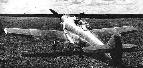
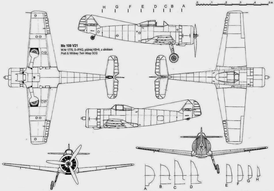
After the success of a demonstration at Zürich in 1937, Udet was receptive to the idea of developing an export version of the Bf 109 but with a different engine than the DB 601.
The engine chosen was the P&W “Twin Wasp” SC-G of 1200 hp. The Messerschmitt company received a contract from RLM/LC on 13 June 1938 to fit the P&W Twin Wasp on the Bf 109 V21 (21st prototype) Werknummer 1770 (D-IFKQ).
Even the maiden flight date is not known; it is established that Hermann Wurster flew it at Augsburg on 17 August 1939 and in September 1940 it was part of the DVL (Deutsche Versuchsanstalt für Luftfahrt) at Brauschweig-Völkenrode with the Stammkennzeichen code KB+II. Its fate is not known.
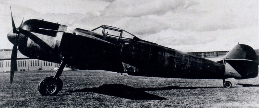
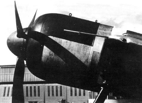
As the BMW 801 radial engine became available, a Bf 109F, Werknummer 5608, callsign D-ITXP was converted with a BMW 801 A-0. This aircraft became a prototype for the Bf 109X.
The fuselage had a wider cross-section, and a new canopy was fitted. The wing tips were similar to that of the Bf 109E.
The prototype was first flown by Flugkapitän Fritz Wendel on 2 September 1940, and the test flights continued despite troubles with the BMW 801A powerplant.