Petlyakov was a Russian designer who headed a bureau before and during Second World War. Notable designs were the PE-2 light bomber and PE-8 four-engined heavy bomber, the latter a development of the 1936 ANT-42 with more powerful engines. The PE-8 entered service in 1941.
World War 2
Percival Aircraft Ltd
Percival Aircraft Ltd formed in 1932 by Australian born aircraft designer Edgar. W. Percival and E. W. B. Leake at Gravesend, Kent, moving to Luton, Bedfordshire, in 1937. Built series of successful light aircraft beginning with the single-engine Gull and later twin-engine Q-6 six/seven seat cabin monoplane. Percival Gulls were used for a number of record-breaking flights, and the type was developed into the Proctor light communications aircraft. Several Mew Gull racers were built in the late 1930s. After Second World War, production of the Proctor continued for civilian customers, while a new three-seat trainer, the Prentice, appeared in 1946 and was built in quantity for the RAF and several overseas air forces. It was followed by the Provost trainer, ordered for the RAF in 1951. Following the experimental Merganser light transport of 1946, a larger version, the Prince, flew in 1948 and was produced in civil and military versions.
During 1944 the Percival Company was absorbed by the Hunting Group in the UK.
A change of name is announced in April 1954, by Percival Aircraft, Ltd. who will be known as Hunting Percival Aircraft, Ltd. The change of name was to provide more complete identification with the parent Hunting Group, and then Hunting Aircraft in 1957.
Pause, Rudolf
In 1929 Rudolf Pause caused a sensation with a muscle-powered swing plane developed in his company. From a hill on what is now Bodenseestrasse, Pause takes “incredible” leaps in the air, according to the archive authors, with a range of twelve meters.
According to the plans of designer Adalbert Schmid, who works for him, they build a swing-wing glider. On June 26, 1942, the muscular-strength aircraft will set out on a 900-meter flight on a meadow on Agnes-Bernauer-Strasse, where the Westbad is today. If you believe the pause experts from the Pasinger Archive, then it was the world’s first manned swing flight.
As a result, Schmid and Pause will of course equip the swing wing with motors, but the project comes to an abrupt end. The Nazi rulers believe that it is not important to the war effort.
Paulista CAP-8
The Companhia Aeronáutica Paulista CAP-8 of 1944 was a four-seat, single-engine low-wing monoplane with enclosed cockpit and fixed (retractable planned in series aircraft) undercarriage, inspired by Messerschmitt Bf 108 Taifun. Only one was built.
Pashinin I-21 / IP-21

In 1939 Pashinin was appointed chief builder of the OKB at Factory No.21. This small collective presented in November of that year the conceptual drawings of a new M-105 powered fighter, which in the factory was called IP-21 (Factory Pashinin Fighter 21 – И стребитель П ашинина завода № 21) or just I-21, a development of the Polikarpov I-16.
Using an M-105 engine, between 60 and 70% of the parts of the new fighter were similar to those used in the I-16, which was calculated to allow the new model to be quickly introduced into the production lines.
The calculations presented by the OKB recorded a takeoff weight of no more than 2400 kg. The calculated maximum speed at sea level reached 523 km/h and at 5000 meters it was 613 km/h (the NII VVS specialists set it at 605 km/h. The ceiling was calculated at 10,400 meters and the ascent time to 5,000 meters – 4.75 minutes.
This new fighter was designed with the M-107 liquid-cooled 1,650 hp inline enginebut the problems presented during the tuning of the engine delayed its production, so the project had to be redesigned to install the M-105 of 1050 hp.
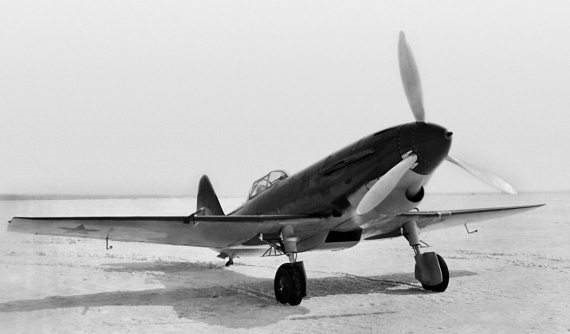
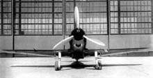
Structurally the I-21 was designed as a conventional monoplane tail, low-wing fighter of mixed construction. The forward section of the fuselage up to the cockpit was based on a structure of welded steel tubes covered with duralumin slats. The tail section featured a monocoque structure covered with wood veneers on a pine wood structure. The frames were similar to those of the I-16 with a 3mm skin tapering to 1.5mm at the tail.
The three-section wings featured a centerplane constructed of chrome steel tubing with aluminum ribbing and covered with plywood. A totally new feature was the symmetrical wing configuration with NACA-0012-0009 profile (at the ends). This new wing theoretically allowed speeds of up to 950 km/h to be reached in a dive. Detachable consoles with rounded ends, were constructed of plywood-faced wood and featured control surfaces along the full span of the trailing edge.

The tail was of a conventional monoplane type. The empennage was made of wood and was removable. The stabilizers were also projected in wood. The control surfaces were similar to those of the Polikarpov I-16, constructed of cloth-covered duralumin.
The landing gear was of the conventional type with a tailwheel. The main units featured a single 600х180 mm wheel that retracted backwards making a 90º turn. Once stowed, the main units and wheels were covered by a cover that projected forward of the wing leading edge where the oil coolers were located.
The cockpit was enclosed and featured a closed bubble-type canopy, allowing visibility in all directions. The deck was unarmored.
The fuel system consisted of five 400-litre tanks, two in the fuselage and three in the midplane.
The I-21’s armament consisted of a ShBAK cannon firing through the engine shaft with 190 rounds and two ShKAS synchronized machine guns with 500 rounds each.
After some revisions, on January 3, 1940, the NKAP leadership approved the construction of the prototype at Factory No.21, granting it the manufacturing index “ Object 30 ”.
On April 4, 1940 the construction of a prototype of the I-21 single-engine fighter with M-105P power plant was approved (the first version produced in series. It could accommodate an automatic cannon between the two rows of cylinders), which was finished in June.
On July 11, 1940, the first prototype of the I-21 took flight for the first time with P. U Fokin at the controls in a flight that lasted 18 minutes. In the factory tests, 33 flights were carried out with a total of 16 hours and included the execution of acrobatics. Pavel Fokin considered that the plane behaved well during takeoff, responded well to controls, was stable in a dive, and both takeoff and landing was easier than the I-16. Preliminary data predicted a speed of 628 km/h and a range of 780 km/h. It was recommended to work on directional stability.
In August the I-21 was transferred to Moscow, being shown on 18 August 1940 at the air festival in Tushino and then delivered for state tests at the Moscow Central Airfield.
During the development of the tests carried out by the test pilots P. Stefanovsky and S. Suprún, it was found that the I-21 had little longitudinal stability in the air, so it was returned to the factory to correct the defect. It was also found that it had a tendency to dive on the wing at large angles of attack, which led to the redesign of the wing and the installation of automatic control surfaces.
However, the NKAP had high hopes for this fighter, so at the end of 1940 the people’s commissar AI Shajurin approved the construction of another pair of prototypes. They were to solve the problems raised by the military. The second example with factory number No.21A213 was ready by August 18, also with an M-105P engine instead of the M-107.
To reduce the stability problem, the builders on the second model introduced a wing with a small sagging on the leading edge.
On October 6 it was taken to the aerodrome and on October 8 the first flight took place, again piloted by Fokin and lasting 17 minutes. The second flight took place on September 12, followed by a third on the 17th with factory pilot Bolshakov and another two in September, finishing factory tests in October 1940. In all flights the plane behaved without difficulties. Weapons tests were at the Factory No.21 until November 14.
The first example was damaged during a landing in the factory tests and it was decided not to repair it, so the state tests were continued on November 21, 1940 with the second example and lasted until the end of 1940. The results obtained were disappointing. The noted defects had not been fixed and furthermore, the modifications had slowed down and other features had deteriorated. The test results showed a maximum speed at sea level of 488 km/h and 573 km/h at 5000 meters. The landing speed increased considerably.
Taking into account the indications of the NII VVS during the tests of the first two examples, a third I-21 prototype was built in January 1941, which flew for the first time on April 5 of that year.
This example had a wing with greater rake on the leading edge and rectangular endings. Each wing console was decreased by 78 cm. The two underwing oil radiators of the previous examples were replaced by a single radiator located in the lower part of the power plant. The height of the water radiator was decreased. On the engine, instead of the independent exhausts, a manifold was located. The surface of the empennage was slightly increased (0.21 sq.m).
The armament of the third prototype was strengthened by replacing the 20 mm ShBAK cannon with a 23 mm BT- 23 cannon in the engine, keeping the two synchronized ShKAS machine guns.

By that time, NN Polikarpov had already developed his modernized version of the I-16, which was released as I-180 and had features not inferior to those of the I-21. Factory No.21 had been selected for series production, but despite the order being given, Pashinin diverted a large number of engineers to development of the I-21, virtually preventing the introduction of Polikarpov’s model into production. The factory management supported Pashinin ‘s work and by 1941 production plans were prepared for the I-21 instead of the I-180. This “misstep” prepared by Pashinin would soon turn against him, and while Nikolai Polikarpov managed to produce at least a few pre-series aircraft, Pashinin’s luck was not on his side.
On November 10, 1940, by order of the NKAP, Semyon Lavochkin ‘s OKB was transferred to Factory No.21. In this document itself, the construction and testing of the I-21-3 was completed.
Between May and June 1941, the I-21-3 was delivered to the LII for tests, in which a speed of 506 km/h and 580 km/h at 4750 meters was reached, which meant 66 km/h more at sea level and 34 km/h higher than the Messerschmitt Bf-109E, the main German fighter at the time. The I-21 also had more firepower than the German fighter, due to the caliber of the cannon being higher, as was the initial velocity of the bullets. The I-21-3 presented better stability and handling, as well as simplicity in piloting, but its landing characteristics required long runways.
The report with the results of these tests was sent by the LII to the Deputy People’s Commissar for the Aircraft Industry AS Yakovlev. It highlighted:
“The I-21 was tested twice at the NII VVS, where it presented several defects for which the tests were interrupted and the prototype was returned to the factory for modifications. For the third time the I-21 with improvements was delivered for control tests to the LII, as a result of which the main conclusions obtained by the NII VVS are confirmed”.
As a result, it was decided not to submit the I-21 to state tests. With this, the development of the model came to an end. The development of a pre-series of 5 copies was stopped.
I-21-3
Powerplant: 1 x 1050 hp M-105P
Wingspan: 9.40 m
Wing area: 15.46 m²
Length: 8.29m
Height: 3.24m
Empty weight: 1210 kg
Takeoff weight: 2670 kg
Wing loading: 173 kg/m²
Power load: 2.5 kg/hp
Maximum speed at sea level: 488 km/h
Speed at altitude: 573 km/h
Landing speed: 165 km/h
Practical range: 760 km
Endurance: 2 hours
Turning time: 25 sec.
Ascent time to 5000 m: 6 min
Take-off run: 282 m
Maximum rate of climb: 1260 m/min (21 m/sec)
Service ceiling: 10600 m
Accommodation: 1
Armament: One 23mm BT-23 cannon and two 7.62mm ShKAS machine guns

Packard XJ49
In 1943, Packard leased a government-owned manufacturing plant located on the outskirts of Toledo, Ohio. The plant was previously operated by the defunct Aviation Corporation. Packard used the leased plant to manufacture parts for the Rolls-Royce Merlin engine, and referred to it as its Toledo Division. In the early-summer of 1944, the Army Air Force Material Command contracted with Packard to carry out “advanced aircraft engine development” on both the Merlin and gas-turbine engines. To oversee the new project, Packard hired Allison Engine Company’s Robert M. Williams as their chief design engineer at the Toledo facility in July of that year. In October 1946 Williams and Dr. George F. Wislicenus, one of the engineers working under him, discussed ways of improving the efficiency of turbojet engines. They came up with an engine design which they called a “ducted fan”. The resulting engine was Packard’s model PT-205, with the military designation Packard XJ49-V-1 turbofan engine.
The XJ49 design was a break from conventional design practices of the time. Most turbojet engines then used one centrifugal compressor, one turbine wheel and multiple combustion chambers that resembled long cylinders arranged in a conical pattern. The XJ49 design had a two-stage compressor made up of an axial-flow supersonic compressor at the engine intake, driven by the second power turbine wheel, followed by a spirally-shaped mixed flow compressor, driven by the first turbine wheel, giving an over-all compression ratio of 6:1.
Power from the annular combustion chamber exhaust drives the complex two-stage turbine. The discharge flow from the first turbine stage drives an independent two-stage turbine. The blades of the last stage of the second turbine are extended beyond the engine core to form a supersonic fan that provides air flow around the engine core for additional thrust and further combustion. Supplementary burning (reheat or afterburning) between the two turbines and in the tailpipe can also be used for additional thrust.
The period between drawing up the basic design theory and a having a complete engine ready to make its first run on a test stand was unusually short, as Packard started testing the first (and only) XJ49 in November 1948. When the testing was complete, the XJ49 proved itself to be the most powerful jet engine in operation at the time.
On September 16, 1959 the United States Air Force released the XJ49 engine to the National Air Museum (now the National Air and Space Museum), and is now in storage at their Silver Hill, Maryland facility.
Specifications:
XJ49-V-1
Type: Ducted Fan (Turbofan)
Compressor: Compound: Two-stage compressor (an axial-flow supersonic 1st stage followed by a mixed flow second stage)
Combustors: Annular
Turbine: Compound: The gas discharge from the first stage turbine drives the following two-stage turbine. The blades of the last stage of the second turbine section extend outside of the engine core to form a supersonic bypass fan.
Maximum thrust: Take-off: 12,000 lb, military: 11,000 lb, normal: 10,000 lb, cruising: 2,560 lb at 35,000 ft.
Overall pressure ratio: Over-all pressure ratio of 6:1
Packard V-1650 / Merlin
In June 1940, Henry Ford had offered to manufacture 1,000 aircraft a day if the government would let him do it his way, and during a discussion with Secretary of the Treasury Henry Morgenthau Jr. regarding what the Ford company might produce, Ford’s son Edsel tentatively agreed to make 6,000 Rolls-Royce liquid-cooled engines for Great Britain and 3,000 for the U.S. However, at the beginning of July, Henry Ford stated that he would manufacture only for defense, not for Britain, and the entire deal was declared off. Members of the Defense Advisory Commission subsequently began negotiations with other manufacturers in an effort to place the $130,000,000 Rolls-Royce order, and Packard Motor Car Company was eventually chosen because the engine’s British parent company was impressed by its high-quality engineering. Agreement was reached in September 1940, and the first Packard-built engine, designated V-1650-1, ran in August 1941.
The first American version of the Merlin was the Packard Merlin 28 (Mark XX), designated the V-1650-1 by the American military. This engine used a single-stage, two-speed supercharger. The two-speed gearing was – as well as for the “R-R” Merlins – from a French Farman patent license. As the Merlin 28, it was used for the Avro Lancaster bomber. The USAAF V-1650-1 version of this engine was used in the Curtiss P-40Fs. The initial Packard modifications to this engine changed the main crankshaft bearings from a copper lead alloy to a silver lead combination and featured indium plating. This had been developed by General Motors’ Pontiac Division to prevent corrosion which was possible with lubricating oils that were used at that time. The bearing coating also improved break-in and load-carrying ability of the surface.
The real improvement Packard incorporated into the Merlin was adopting the Wright supercharger drive quill. This modification was designated the V-1650-3 and became known as the “high altitude” Merlin destined for the P-51. The two-speed, two-stage supercharger section of the V-1650-3 featured two separate impellers on the same shaft that were normally driven through a gear train at a ratio of 6.391:1. A hydraulic gear change arrangement of oil operated clutches could be engaged by an electric solenoid to increase this ratio to 8.095:1 in high speed blower position.
The high speed gear ratio of the impellers was not as high as the ratio used in the Allison, but impeller speed is not the only factor that determines engine performance, which is also a function of the size and pitch of the impeller blades. The gear-driven supercharger is a parasitic accessory; therefore, impeller gearing and blade profiles are carefully designed for maximum power at altitude without compromise of available power at the critical take off stage of flight. The double staging of the compressed fuel/air mixture provided the boost pressure through a diffuser to the intake manifolds that increased the critical altitude of the power plant.
The ability of the supercharger to maintain a sea level atmosphere in the induction system to the cylinders allowed the Packard Merlin to develop more than 1,270 horsepower (950 kW) at altitudes beyond 30,000 feet (9,100 m). The two-stage impeller created extreme heating of the fuel/air mixture during the compression process and to prevent detonation of the compressed charge, it was necessary to cool the mixture prior to entry into the cylinders. The cooling was accomplished in an intercooler passage cast into the wheel case housing between the first and second stage impellers.
Ethylene glycol coolant was circulated by a pump through this passage to carry off the excess heat generated by the impellers. Without the intercooler the temperature of the charge could be as high as 400 °F (204 °C). The intercooler in itself was not adequate to deal with the high temperature and an additional cooling fin and tube core was placed between the outlet of the blower and the induction manifold to the cylinders. This radiator was known as an aftercooler and served as a reservoir for the supercharger cooling system. The glycol mixture used for cooling was independent of the main engine cooling system and used a centrifugal pump driven by the engine to circulate the coolant through an aircraft radiator system at a maximum rate of 36 U.S. gallons (136 litres, 30 Imperial gallons) per minute, depending on engine rpm. This combined system reduced the charge temperature to suitable levels.
Throttle valves in the updraft carburettor throat were controlled by an automatic boost control through the throttle linkage to maintain the selected manifold pressure with changes in altitude. The valves were only partially open during ground and low level operation to prevent overboosting of the engine. As air density decreases with increased altitude, the throttle valves were progressively opened in response to the reducing atmospheric pressure. This system provided full power within engine boost limitations up to the critical altitude of 26,000 feet (7,900 m).
It found its most famous application in the North American P-51 Mustang fighter, where it vastly improved that aircraft’s performance at altitude, transforming the Mustang into an outstanding fighter with the range and performance to escort heavy bombers over the European continent. By 1944, P-51B, P-51C and P-51D “Merlin” Mustangs were able to escort Allied heavy bombers in daylight all the way to Berlin and yet were still capable of combating German fighters attempting to intercept the bombers. By late 1944, the Allies had won air supremacy over the whole of Germany, and Germany’s defeat in World War II began to appear inevitable.
A total of 55,523 were built.
In the United States many war surplus engines and airframes were sold relatively cheaply – two of the most popular items were North American P-51 Mustangs and Packard V-1650 Merlin engines, several of which were “souped up” and modified for air racing in the Bendix Trophy, the Cleveland Air Races, and the Thompson Trophy.
Work continues on increasing the power output of the Merlin for the Unlimited Class racers at the Reno Air Races. Innovations, such as the use of Allison V-1710 connecting rods and the replacement of the intercooler with ADI (Anti-Detonate Injection) (50% Distilled Water and 50% Methanol), essentially the same idea as the Water Injection system used on Pratt & Whitney engines during World War II, have allowed great increases in power output. Many of the fastest Unlimited racers increase Merlin manifold pressures as high as 145 inHg (56.6 psi, 4.8 atm) to obtain the 3,800 horsepower, achieving Mustang speeds up to 490 mph.
Variants:
V-1650-1: 1,390 hp (1,040 kW); Based on Merlin 28, used in P-40 Kittyhawk and Curtiss XP-60 fighters
V-1650-3: 1,280 hp (950 kW); Based on Merlin 63.
V-1650-5: 1,400 hp (1,000 kW); Experimental.
V-1650-7: 1,315 hp (981 kW); Similar to Merlin 66, primary powerplant of the P-51D Mustang.
V-1650-9: 1,380 hp (1,030 kW); 2,218 hp WEP with Water methanol injection.
V-1650-9A: 1,380 hp (1,030 kW);
V-1650-11: 1,380 hp (1,030 kW); Modified fuel system.
V-1650-21: 1,380 hp (1,030 kW); Opposite rotation for P-82 Twin Mustang
V-1650-23:
V-1650-25:
Applications:
Avro Lancaster B Mk III/B Mk X
Bell XP-63
Curtiss P-60
Curtiss P-40F/L Kittyhawk
de Havilland Mosquito B Mk VII/B Mk 25
Hawker Hurricane Mk.X, XI, XII
North American P-51 Mustang
North American F-82 Twin Mustang
Supermarine Spitfire Mk.XVI
Specifications:
V-1650
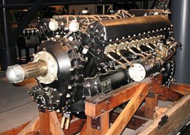
Type: 12-cylinder supercharged liquid-cooled 60° “Vee” piston aircraft engine
Bore: 5.4 in (137.2 mm)
Stroke: 6 in (152.4 mm)
Displacement: 1,649 cu.in (27.04 lt)
Length: 88.7 in (2,253 mm)
Width: 30.8 in (781 mm)
Height: 40 in (1016 mm)
Dry weight: 1,645 lb (746 kg)
Valvetrain: Overhead camshaft-actuated, two intake and two exhaust valves per cylinder, sodium-cooled exhaust valve stems
Supercharger: Two-speed two-stage, boost pressure automatically linked to the throttle, water-air aftercooler installed between the second stage and the engine.
Fuel system: Twin-choke updraft carburettor with automatic mixture control
Fuel type: 100 Octane, from mid 1944 100/150 Grade Aviation fuel
Oil system: Dry sump with one pressure pump and two scavenge pumps.
Cooling system: 70% water and 30% ethylene glycol coolant mixture, pressurized.
Specific power: 0.95 hp/cu.in (43.3 kW/L)
Compression ratio: 6:1
Power-to-weight ratio: 0.80 hp/lb (1.73 kW/kg) take-off; 1.21 hp/lb (2.69 kW/kg) 100/150 grade fuel/MS gear.
Packard
Packard Motor Co
Packard was founded in 1899 by two brothers, James Ward Packard (5 November 1863 – 20 March 1928) and William Doud Packard (November 3, 1861 – November 11, 1923) of Warren, Ohio who ran the Packard Electric Company. In 1926 about 20 New York business men, including James Packard, and a group of US Navy officers expressed an interest in building an airplane designed to break the standing air speed record. Navy officials agreed that they would finance the proposal when funds became available. The aircraft was to be completed in time to participate in the 1927 Schneider Trophy Race, which would be held in Italy.
The engine was designed by Navy Captain Lionel Melville Woolson, an aeronautical engineer at the Packard Motor Company of Detroit. The engine was an “X” configured design similar to one upright and one inverted V-12 engine mounted on the same crankshaft with a common crankcase. With 5.375 in (136.5 mm) bore and 5 in (130 mm) stroke, the resulting displacement was 2,775 cu in (45.47 l). The Packard X-2775 engineering involved in the design of the crankshaft, single piece crankcase and the master/slave rod system was very complex.
Oberursel
Motorenfabrik Oberursel
Motorenfabrik Oberursel A.G. was a German manufacturer of automobile, locomotive and aircraft engines situated in Oberursel (Taunus), near Frankfurt (Main), Germany. The company had its origins in 1891, when Willy Seck invented a new gasoline fuel injection system and produced a small one-cylinder stationary engine of about 4 hp, which he called the Gnom. The following year he founded Willy Seck & Co. to sell the design, which became famous around the world. The engine was improved to achieve more power, but in 1897 the shareholders refused to allow Seck to develop a Gnom-powered car and he left the company. The company was reorganized as Motorenfabrik Oberursel the next year, and by 1900 had built 2,000 engines.
The same year the company granted a license to the Seguin brothers in Lyon to produce the Gnom in France. Sold under the French name Gnome, the engine became so successful that they renamed their company to the same name. In 1908 they developed a rotary version of the basic Gnome system as the Gnome Omega aircraft engine, and from there a series of larger versions of the same basic design. The new Gnome engines were wildly successful, powering many of the early record breaking aircraft.
In 1913 Motorenfabrik Oberursel took out a license on the French Gnome engine design and the similar Le Rhône 9C. They produced both, the Gnomes as the U-series, and the Le Rhônes as the UR-series. During World War I it supplied a major 100 hp-class rotary engine that was used in a number of early-war fighter aircraft designs.
The Gnome Lambda seven-cylinder 80 hp rotary engine was also produced by the Oberursel firm as the Oberursel U.0 Umlaufmotor (the generic German term for a rotary engine) as their first-ever powerplant for German military aircraft, and was used on the initial versions of the Fokker Eindecker fighter, the Fokker E.I.
When World War I started the following year the Oberursel U.I of 100 hp, a clone of the Gnome Delta 100 hp rotary, had the best power-to-weight ratio of any German engine. It went on to power most of the early German fighters, such as the Fokker and Pfalz E-series monoplanes
.
Oberursel also built a copy of Gnome’s 14-cylinder Double Lambda two-row rotary. This 160 hp (120 kW) engine, designated U.III in Germany, was difficult to build and quickly wore out in service. It was used on the Fokker E.IV and D.III designs.
The 110 hp Oberursel UR.II, the clone of the Le Rhône 9J of the same power output, was the next major success. Fokker bought the company in 1916 in order to guarantee supplies of the UR.II. This acquisition proved advantageous because Fokker was partial to rotary powered designs, and because supplies of the Mercedes D.III engine were limited. The UR.II was used in the Fokker Dr.I and Fokker D.VI.
By 1917, the UR.II had been rendered obsolete by its relatively low power and poor performance at altitude. An 11-cylinder development, the UR.III, was not used operationally. Indeed, by 1918, rotary engines had largely fallen from favor with the Idflieg and with pilots. The lack of castor oil and the poor quality of the mineral oil substitute “Voltol” severely reduced engine life and reliability.
Nevertheless, in the summer of 1918, the UR.II was installed in the Fokker D.VIII. The light weight and aerodynamic cleanliness of the D.VIII allowed it to achieve excellent performance even with the outdated UR.II.
After the war the company was purchased in 1921 by Gasmotorenfabrik Deutz, another gasoline engine manufacturer, who moved their two-stroke diesel manufacturing to the Oberursel factories. In 1930 they merged with Humboldt-Deutz, but with only one product line. The factory was eventually closed in 1932 during the Great Depression, reopening in 1934 for small-scale production.
In 1938 the company merged Klöcknerwerke AG. From this point on they were known as the Klöckner-Humboldt-Deutz Oberursel factory, known primarily for their locomotive engines.
In 1940 during World War II all diesel research was relocated to Oberursel, where Dr. Ing. Adolf Schnürle led the development of much larger and more advanced engines for aircraft use. This led to the Klöckner-Humboldt-Deutz DZ 700 8-cylinder radial engine, the DZ 710 16-cylinder boxer engine, and the DZ 720 32-cylinder H-block made from twinned 710’s. None of these designs reached operational use by the end of the war, when the factory was occupied by US troops.
For a short period in 1946 the factories were used as a tanks and trucks repair depot by the US army.
In 1956 the factories were returned to Klöckner-Humboldt-Deutz, and from then on have been used primarily for gas turbine development and production. For the next twenty years they produced a variety of designs, typically under license from other companies. In 1980 they were renamed KHD Luftfahrttechnik GmbH.
In 1990 the company was sold to what was then BMW Rolls-Royce. The new owners decided to use the Oberursel plants to produce an entirely modern engine for the “small end” of the aviation market, and started development of the Rolls-Royce BR700 family in 1991. The engines have since gone on to power a number of aircraft including Bombardier, Gulfstream V and the Boeing 717.
The factory in Oberursel is claimed to be the oldest surviving aircraft engine factory in the world.
Engines:
Gnome designs:
Oberursel U.0
licensed Gnome 7 Lambda, 68 hp (51 kW) seven cylinder rotary.
Oberursel U.I
100 hp (75 kW), nine cylinder.
Oberursel U.II
110 hp (82 kW)
Oberursel U.III
Gnome Lambda-Lambda 14-cylinder, two-row rotary engine copy. 160 hp (120 kW).
Le Rhône designs:
Oberursel Ur.II
Le Rhone 9J 110 hp (82 kW) nine cylinder rotary.
Oberursel Ur.III
11-cylinder development of the Ur.II. 145 hp (108 kW).
Oberlerchner, Joseph
Austria
The firm of Josef Oberlerchner Holzindustrie had become the foremost Austrian sailplane manufacturer, producing over 4,000 gliders and powered aircraft between 1941 and 1967, of which the Mg 19 tandem two-seater trainer and the Mg 23 high performance single-seater were the most important postwar types. Before the war Austria had produced some notable sailplanes, in particular the Mg series designed by Ing Erwin Musger which culminated in the Mg 19 and Mg 23.
A former manufacturer of sailplanes, Oberlerchner flew a prototype all-wood two-seat JOB 5 lightplane in 1958. The developed JOB 15 four-seater, which had metal/wood/glassfibre construction, entered production in 1961, powered by a Lycoming engine. It remained in service with Austrian and other European aero clubs, especially as a glider tug.
