This was the last of the line of reciprocating, liquid-cooled units. The initial design project was conceived toward the end of 1942 as the necessity for a higher-powered engine was foreseen. The Rolls-Royce design team realised that producing a scaled-up version of their Griffon V-12 engine would lead to excessively large combustion chambers and problems with detonation.
Considerations of aspiration and flame travel set a more or less effective limit of about 6 inches to bore size, and with cylinders of this order it has been established that 12 pistons per crankshaft is about the practical limit and considered an X-24 design. This layout had previously caused unreliability with the Rolls-Royce Vulture due to the need to fasten four connecting rods in a complicated arrangement to a common big end bearing.
The designers finally settled on an ‘H’ layout with two crankshafts and ‘blade and fork’ connecting rod attachments, the crankshafts being connected through the propeller speed reduction unit. Sleeve valves were decided upon in view of the fact that they offer advantages over poppet valves from the aspect of maintenance and obviation of adjustment.
The case is split vertically into port and starboard halves of cast light alloy, the front wall carrying the tail bearings for the timing gears uniting the crankshafts. Cylinder blocks are also examples of sandcasting technique in light alloy, the upper and lower rows of cylinders on each side being formed in one casting. Each cylinder is ventilated with three inlet and two exhaust ports, the latter ports of each vertical pair of cylinders discharging to a common pair of ejector stacks.
Sleeve drive is by a worm shaft on each side commonly serving top and bottom rows of sleeves, each shaft running in six split plain bearings.
A two-speed, two-stage supercharger and intercooler were used to compress then cool the air-fuel mixture, following Griffon and Merlin practice. Starting was by Coffman starter. An auxiliary shaft driven by the lower crankshaft operated the main coolant pump, intercooler coolant pump, pressure and scavenge oil pumps and a fuel injection pump. Piston ring failures and cylinder head sealing problems were experienced during early flight testing.
Rolls-Royce Eagle 22
It was designed and built in the early-1940s and first ran in March 1944. The Eagle was never fitted to a production front-line fighter, as it was overshadowed by a new wave of turbojet engines, such as the Rolls-Royce Derwent and turboprops such as the Dart and Armstrong Siddeley Python. Fifteen Eagle 22s were produced to power the prototypes of the Westland Wyvern fighter / torpedo bomber as its intended powerplant, the AS Python was late in development.
Early Eagles (I and II) drove a single airscrew, but the Eagle 22 was arranged for contraprops in view of its application to the Westland Wyvern T.F.1 deck-landing strike fighter. In M. S. gear the Eagle delivered 3,415 h.p. at 3,500 r.p.m. for take-off. The maximum power rating in M. S. gear was 3,500 h.p. at 3,250 ft, and in F. S. gear, 3,020 h.p. at 15,250 ft.
Variants: 46H Eagle I (1944) – Compression ratio 6.5:1
46H Eagle II (1944) – Modified Eagle I
46H Eagle (20 srs) 22 (1946-1949) – Increased compression ratio (7:1), Fifteen engines produced at the Derby Rolls-Royce factory. First flown in a Westland Wyvern on 16 December 1946.
Specifications: Eagle 22 Type: 24-cylinder liquid-cooled H-type aircraft piston engine Bore: 5.4 in (137 mm) Stroke: 5.125 in (130 mm) Displacement: 2,807 in³ (46 L) Length: 135.5 in (3442 mm) Width: 43.4 in (1,102 mm) Height: 50.0 in (1,270 mm) Dry weight: 3,900 lbs (1,769 kg) Valvetrain: Sleeve valves Supercharger: Two-speed, two-stage supercharger, maximum boost +18 lb Fuel type: 115/150 Octane petrol, DERD 2476 Cooling system: Liquid-cooled, 70% water, 30% ethylene glycol Reduction gear: Geared spur, 0.2985:1 reduction ratio. contra-rotating right-hand/left-hand tractor Power output: 3,200 hp (2,387 kW) at 18 lb (124.1 kPa) of boost at 3,500 rpm Specific power: 1.13 hp/in³ (51.7 kW/L) Compression ratio: 7:1 Power-to-weight ratio: 0.82 hp/lb
When Rover was selected for production of Whittle’s designs in 1941 they set up their main jet factory at Barnoldswick, staffed primarily by various Power Jets personnel. Rover felt their own engineers were better at everything, and also set up a parallel effort at Waterloo Mill, Clitheroe. Here Adrian Lombard developed the W.2 into a production quality design, angering Whittle who was left out of the team. Lombard went on to become the Chief Engineer of the Aero Engine Division of Rolls-Royce for years to come.
After a short period Lombard decided to dispense with Whittle’s “reverse flow” design, and instead lay out the engine in a “straight-through” flow with the hot gas exiting directly onto the turbine instead of being piped forward as in Whittle’s version. This layout made the engine somewhat longer and required a redesign of the nacelles on the Meteor, but also made the gas flow simpler and thereby improved reliability. While work at Barnoldswick continued on what was now known as the W.2B/23, Lombard’s new design became the W.2B/26 centrifugal compressor turbojet engine.
By 1941 it was obvious to all that the arrangement was not working; Whittle was constantly frustrated by what he was seeing as Rover’s inability to deliver production-quality parts for a test engine, and became increasingly vocal about his complaints. Likewise Rover was losing interest in the project after the delays and constant harassment from Power Jets in the critical testing process stage, where testing new designs and materials to breaking point is vital. Earlier, in 1940, Stanley Hooker of Rolls-Royce had met with Whittle, and later introduced him to Rolls’ CEO, Ernest Hives. Rolls had a fully developed supercharger division, directed by Hooker, which was naturally suited to jet engine work. Hives agreed to supply key parts to help the project along. Eventually Spencer Wilks of Rover met with Hives and Hooker, and decided to trade the jet factory at Barnoldswick for Rolls’ Meteor tank engine factory in Nottingham. A handshake sealed the deal, turning Rolls-Royce into the powerhouse it remains to this day. Subsequent Rolls-Royce jet engines would be designated in an “RB” series, standing for Rolls Barnoldswick, the /26 Derwent becoming the RB.26.
Problems were soon ironed out, and the original /23 design was ready for flight by late 1943. This gave the team some breathing room, so they redesigned the /26’s inlets for increased air flow, and thus thrust. Adding improved fuel and oil systems, the newly named Derwent Mk.I entered production, the second Rolls-Royce jet engine to enter production, with 2,000 lbf (8.9 kN) of thrust. Mk.II, III and IV’s followed, peaking at 2,400 lbf (10.7 kN) of thrust. The Derwent was the primary engine of all the early Meteors with the exception of the small number of Welland-equipped models which were quickly removed from service. The Mk.II was also modified with an extra turbine stage driving a gearbox and, eventually, a five-bladed propeller, forming the first production turboprop engine, the Rolls-Royce RB.50 Trent.
The project was to be of the same maximum diameter, in order that it might be installed in standard Meteor nacelles, but it was to develop 2,000 lb thrust. Drawings were started in April 1943 and by July the new unit was ready for test. In November of that year it passed its 100-hr type-test at the full 2,000 lb rating and in April the following year it went through its first flight tests in a Meteor, with a Service rating of 1,800 lb and a weight of 920 lb.
The Derwent II gave a thrust of 2,200 lb, and the III was a special unit to provide suction for boundary-layer removal; the Derwent IV was rated at 2,400 lb thrust. The Derwent 5 was an entirely new engine-still of 43in diameter, but developing twice the thrust of the original Derwent I. It was, in effect, a scaled-down version of the Nene, and its development was motivated by the promise shown by the Nene and the knowledge that the Meteor could utilize thrust greatly in excess of the original estimates.
The basic Derwent design was also used to produce a larger 5,000 lbf (22.2 kN) thrust engine known as the Rolls-Royce Nene. Development of the Nene continued in a scaled-down version specifically for use on the Meteor, and to avoid the stigma of the earlier design, this was named the Derwent Mk.V. Several Derwents and Nenes were sold to the Soviet Union by the then Labour government, causing a major political row, as it was the most powerful production-turbojet in the world at the time. The Soviets promptly reverse engineered the Derwent V and produced their own unlicensed version, the Klimov RD-500. The Nene was reverse-engineered to form the populsion unit for the famous MiG-15 jet fighter. The Derwent Mk.V was also used on the Canadian Avro Jetliner, but this was never put into production.
On 7 November 1945, a Meteor powered by the Derwent V set a world air speed record of 606 mph (975 km/h) TAS.
An unusual application of the Derwent V was to propel the former paddle steamer Lucy Ashton. The 1888 ship had her steam machinery removed and replaced by four Derwents in 1950–1951. The purpose of this was to conduct research on the friction and drag produced by a ship hull in real life conditions. Jets were preferable to marine propellers or paddles as these would have created a disturbance in the water, and the force exerted by them was harder to measure. The four engines could propel the Lucy Ashton at a speed in excess of 15 knots (28 km/h; 17 mph).
The Derwent 5 was superseded by the Derwent 8 and 9. The 8 incorporated two outlets to feed compressor-air through piping to heater muffs on the exhaust unit; tappings were taken from these muffs to heat the cabin and the guns and/or camera. The 9 used the same method of heating, but had in addition larger combustion chamber-inter-connectors and high-energy ignition to give more consistent relighting in flight as well as to increase the altitude at which relighting was possible.
Experimental Derwents included the RD.9, which had a 15 per cent increase in mass flow, and the RD.10-a scaled-up version utilizing the rotating parts of the Nene. The RD.11 was another scaled-up development.
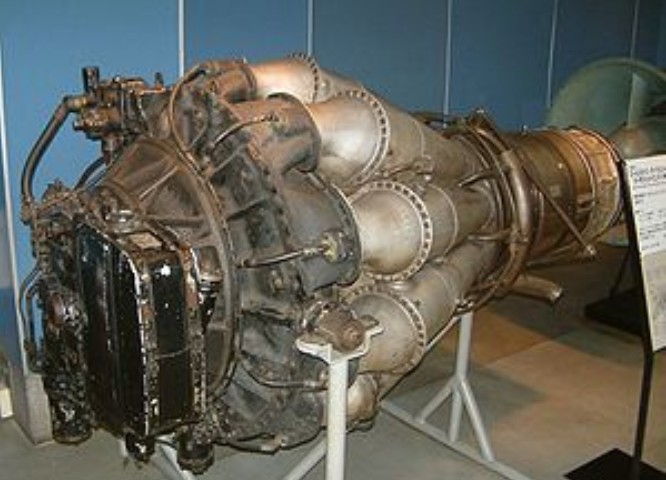
The body of a typical Derwent is built up on the compressor rear casing which, though immensely strong, is very light and is considered by Rolls-Royce to be a fine example of their foundry technique. On the front face are the diffuser ring, the front casing and front air intake, and the wheelcase. To the rear the main structure comprises the rear air intake, the cooling-air casing and the centre and’rear bearing-housings, which successively lead to the nozzle-box assembly. This last takes the gas flow from the combustion chambers and distributes it to the annulus of stationary nozzle-guide vanes; it also carries the auxiliary coolingair ducts leading from the region of the turbine disc and rear bearing housing.
Centrally runs the main rotating assembly, and disposed round the engine, between the compressor casing outlet elbows and the nozzle-box, are the nine combustion chambers. So carefully balanced is the rotating assembly that as much as a minute and a half elapses before it comes to rest after the engine is shut down, At maximum static thrust the characteristic double-sided impeller deals with 62 lb of air per second, with an efficiency of 80 per cent and a compression ratio of 4 : 1. For this task it needs about 8,000 h.p., which is transmitted from the turbine through the coupling. The impeller is 24in in diameter and has 29 vanes on each side. Guide vanes convert axial to radial flow.
Variants: Derwent I – first production version. Straight-thru development of the trombone style W.2 configuration, with compressor and turbine upflowed by 25% to give 2000lbf (8.9 kN) static thrust Derwent II – thrust increased to 2,200 lbf (9.8 kN) Derwent III – experimental variant providing vacuum for wing boundary layer control Derwent IV – thrust increased to 2,400 lbf (10.7 kN) Derwent 5 – scaled-down version of the Rolls-Royce Nene developing 3,500 lbf (15.6 kN) of thrust Derwent 8 – developed version giving 3,600 lbf (16.0 kN) of thrust
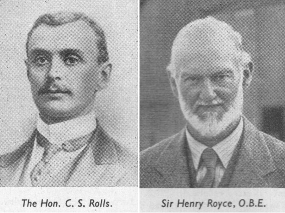
Rolls and Royce, met in Manchester in 1904. Rolls-the Hon. Charles Stewart Rolls-possessed wealth, an Eton-and-Cambridge education, a degree in mathematics and applied science, and a fine record as a motorist. He was a sportsman he had consistently displayed a daring at the wheel and a determined approach to the technical problems of motoring.
In the business of C. S. Rolls and Co., which he established with Claude Johnson in 1902. In 1903 he set a world speed record of 93 m.p.h.; but the car was a 70 h.p. Mors, and by the following year, when his books showed orders for a hundred Continental cars, he could still not find a British product which measured up to his standards.
At ten years of age Henry Royce started work as a telegraph boy, later attending a technical college, and serving a few years in the Great Northern locomotive shops at Peterborough. After a spell in an engineering works at Leeds, he set up a business in Manchester, making arc lamps and dynamos. The slump after the Boer War caused him to turn his ambition to cars. Disappointed with a foreign model which he acquired, he decided to put his own ideas into practice, and in 1903 he completed a two-cylinder car of 10 h.p., having handled much of the precision work himself.
One of his first three cars went to Henry Edmunds, who arranged the meeting in Manchester. The two men took to each other immediately, and having tried out Royce’s car, young Rolls undertook to sell its maker’s entire output. But he began to ply his partner with suggestions and demands.
The “two Rs” were first officially linked in business association at Christmas 1904, by a working agreement between the two firms; and thenceforth the Rolls-Royce car began.
By 1906 Royce’s production was large enough to allow Rolls to stop his sales of other makes of car, and Rolls-Royce, Ltd., was founded. Royce’s old partner, A. E. Claremont, became chairman; Rolls was technical managing director; and Royce was nominated chief engineer and works director.
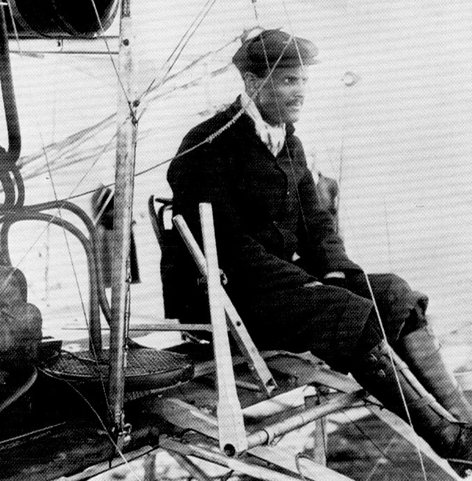
Charles Stewart Rolls
Rolls, who had become a member of the Aeronautical Society in 1901, was already a keen balloonist; then, having met the Wright brothers, he turned to heavier-than–aircraft. He was awarded his pilot’s certificate (No. 2) on March 8th, 1910-the very same day that Lord Brabazon received his No. 1. On the Wright biplane he made the first heavier-than-air crossing of the Channel by an Englishman, and the first double crossing by any aeroplane in history; but soon afterwards-on July 12th, 1910, he crashed to his death at the Bournemouth flying meeting, only 33 years of age. He was the first Englishman to die in an accident to a powered, heavier-than-air machine. His Wright Flyer broke up at 20 ft agl and he cracked his skull.
C.S. Rolls
In 1910 Royce became seriously ill and thereafter was absent for long periods from his new factory at Derby. He worked on in the south of France and on the south coast of England.
Following the British Schneider victory of 1929-made possible by the “R” engine-a baronetcy was conferred upon him, and he heard from his bed how an improved engine of this type sent a Supermarine S.6B to final victory in the Schneider Race of 1931. He died on April 22nd, 1933.
1914 Design of first Rolls-Royce aero engine-later named Eagle started. Company making engines of official pattern at Derby.
1915 Eagle on test six months after design initiated. Hawk designed and developed. Falcon designed
1918 Condor on test at 525 h.p.
1919 Alcock and Brown, in a Vickers Vimy (two Rolls-Royce Eagle Vills), mode first direct crossing of North Atlantic; flying time, 16 hir 12 min. Ross Smith and Keith Smith, in an Eagle-Vimy, made first flight from England to Australia11,130 miles in 124 hr flying time.
1920 Van Ryneveld and Quintin Brand, also in an Eagle-Vimy, made first flight from England to South Africa-6,281 miles in 92 hr 58 min flying time.
Between 1915 and 1924 Rolls-Royce Aero-engine production was: Eagle, 4,674; Hawk, 200; Falcon, 2,185; Condor, 327.
1925 Design of Rolls-Royce “F” series of engines (later called Kestrel) started.
1926 First “F” engine tested and delivered.
1927 The ” H ” engine-later the Buzzard-under development.
1929 Air Ministry decided in February to compete in Schneider Trophy Contest; Rolls-Royce asked to develop a racing engine. Within six months “R” engine was delivering 1,900 h.p. for a weight of 1,350 ]b. Installed in Supermarine S.6, which won Schneider Contest at 328.63 m.p.h.
1931 Rolls-Royce again asked to develop a Schneider Trophy engine to help secure a third victory, which would gain Trophy outright for Gt. Britain. Outcome was improved “R” engine of 2,360 h.p., weighing 1,630 lb. Schneider Trophy won outright. Later “R” engine gave 2,530 h.p. and enabled world speed record to be raised to 407.5 m.p.h.
By 1931, during the Great Depression, Bentley was having financial difficulties. When funds ran out in 1931, the receivers were negotiating with D.Napier & Sons Ltd for the sale of the remains of Bentley. However, Rolls-Royce put in a secret bid through a Liechtenstein company, and secured Bentley Motors for £125,256. For this, Rolls-Royce got the factory equipment, a number of incomplete car chassis, and the services of Walter Bentley for three years.
1932 Design of the P.V.12 engine (later called Merlin) started. (P.V. denoted private venture.)
1934 Merlin completed its first 100 hr run at 790 h.p.
1936 Merlin completed Service Type Test at 975 h.p.
1938 Building of Crewe factory started.
1939 First Merlin built at Crewe. Design and development work started on 37.V.12 engine, later named Griffon. Building of Glasgow factory begun in August. 1
1940 First Merlin built at Glasgow. First test run of Griffon.
1942 Quantity production of Griffon started.
1943 First Rolls-Royce turbojet-the Welland-passed its 100 hr type test; thrust, 1,700 lb, weight, 850 lb. Design of Derwent 1 started.
1944 Deliveries of Welland begun, for installation in Gloster Meteor. Design and development of Nene started.
1945 Meteor powered with Derwent Vs broke world air speed record at 606 m.p.h. In September a Meteor was flown with two Rolls-Royce Trent turboprops, being the first turboprop aircraft to fly. By this year power of Merlin had increased to over 2,000 h.p.
1946 World airspeed record again broken by a Derwent-Meteor; speed 616 m.p.h.
1947 Pratt and Whitney signed licence agreement for manufacture of Rolls-Royce Nene and Toy. Nenes in production at Derby. Trans-Canada Airlines started operations with Merlin powered Canadair North Stars.
1948 First public appearance ofAvon turbojet at S.B.A.C. Display. Belgium signed licence agreement for manufacture of Derwents.
1949 Dart turboprop type-tested at 1,000 h.p. B.O.A.C. intro- duced Merlin-powered Argonauts (similar to North Stars).
1950 Australia signed licence agreement to build Nene and Avon. Hispano signed agreement to make Nene and Toy.
1951 English Electric Canberra, with two Rolls-Royce Avons, made first non-stop transatlantic crossing by a jet aircraft the first of numerous record flights by Avon-Canberras.
1952 Sweden signed licence agreement to build Avon.
1953 Avon-Canberra flew from London Airport to Darwin, Northern Australia, in 22 hr 21 sec. Avon-powered Hawker Hunter established world air speed record of 726.6 m.p.h.; Avon-powered Supermarine Swift later raised record to 735.7 m.p.h. Ministry of Supply opened new factory at East Kilbride, Lanarkshire, to augment production of Avons for the R.A.F. (in addition, Avons were being made by the Bristol Aeroplane Co., Ltd., D. Napier and Son, Ltd., and the Standard Motor Company.)
1954 By May 1954 British-built Rolls-Royce gas turbines had completed 23 million flying hours; Merlins had cornpleted over 5.1 million flying hours in commercial service. By the end of the year over 185,000 Rolls-Royce piston and gas-turbine engines will have been built.
LHTEC (Light Helicopter Turbine Engine Company) is a joint venture between Rolls-Royce and Honeywell founded in 1985. The company was originally a partnership between the Allison Engine Company and AlliedSignal Aerospace . In 1995 Rolls-Royce acquired Allison, and AlliedSignal merged with Honeywell in 1999, and adopted its name.
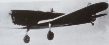
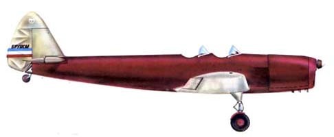
The Rogožarski Brucoš (Freshman, Serbian Cyrillic: Рогожарски Бруцош) was a single-engine, two-seat, low wing monoplane aircraft designed as a trainer in Yugoslavia in 1940. It was designed and built in the Rogožarski aircraft factory in Belgrade. Only one prototype was built.
Engine: 1 × de Havilland Gipsy Major I, 96 kW (129 hp) Propeller: 2-bladed Wingspan: 10.00 m (32 ft 10 in) Wing area: 16.00 sq.m (172.2 sq ft) Length: 8.10 m (26 ft 7 in) Height: 3.10 m (10 ft 2 in) Empty weight: 615 kg (1,356 lb) Gross weight: 872 kg (1,922 lb) Maximum speed: 185 km/h (115 mph; 100 kn) 210 km/h at sea level Range: 840 km (522 mi; 454 nmi) Service ceiling: 4,000 m (13,123 ft) Rate of climb: 2.54 m/s (500 ft/min) Crew: 2
Rockwell-Standard Corp North American Rockwell Corp Rockwell International Corp
In 1919, Colonel W.R. Rockwell reorganised a bankrupt axle company in Oshkosh, Wisconsin. Following the Colonel’s development of the first double reduction axles for heavy-duty vehicles, Timken-Detroit Axle company acquired his axle company in 1928.
In 1953, Timken-Detroit merged with Standard Steel Spring Company to form Rockwell Spring and Axle Company. In 1958, the name of the company was changed to Rockwell-Standard Corporation. Rockwell-Standard embarked on a plan of diversification in the late 1950s and 60s and by 1967, it was a major independent producer of a wide-range of automotive components.
In 1965 Rockwell-Standard acquired Snow Aeronautical, continuing to produce agricultural aircraft at Olney as Snow Commanders (as division of Aero Commander), and acquired Intermountain Manufacturing Company (IMCO) 1966. Single-engined Model 112 delivered to customers from 1972. Low-wing twin-engined Rockwell Commander 700 produced jointly with Fuji in Japan. Thrush Commander was very notable specially-designed agricultural aircraft. The entire Thrush Commander range sold to Ayres Corp and then became known by the Ayres name. Shrike Commander 500S terminated 1980 but Commander Jetprops continued by Gulfstream American Corporation.
In 1967, Rockwell-Standard Corporation and North American Aviation merged to create the North American Rockwell Corporation.
Following company reorganization, the former Aero Commander division of Rockwell became part of NAR, and its Shrike, Commander 685 and Turbo Hawk Commander twin-engined business aircraft were marketed under the new company name, together with Quail, Sparrow, Snipe and Thrush Commander agricultural aircraft, and the Darter and Lark Commander single-engined lightplanes.
The Model 112 Commander lightplane and B-1 swing-wing supersonic bomber projects were started before the company name was changed to Rockwell International in 1973.
In 1973 North American Rockwell and Rockwell Manufacturing Company merged to become Rockwell International Corporation. Aircraft production after the 1967 merger included the Aero Commander line of single and twin-engine aircraft, the turboprop OV-10 Bronco armed reconnaissance aircraft, T-2 Buckeye jet trainer, B-1B Lancer supersonic swing-wing bomber, and the Sabreliner executive and light jet transport. Company’s aerospace and defence units purchased by the Boeing Company on December 6,1996, becoming Boeing North American. Similarly, Rockwell Australia became Boeing Australia Ltd.
In 1977 Rockwell International sold its agricultural airplane operation to the Ayres Corporation of Albany, Georgia. The new owners will continue to manufacture the Models 600 and 800 Thrush Commanders. Fred Ayres, who developed the Turbo Thrush PT6 retrofit, plans to begin producing that airplane at his new plant.
1984: Sabreliner Corporation, a new company formed to acquire the former Sabreliner Division of Rockwell International.
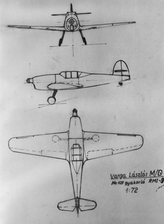
From 1943 the Air Force was gradually getting the Bf-109 advanced jet fighters (F and G versions), but it was not easy to get used to the tight and narrow track undercarriage. The Aero Technical Institute created the RMI-9 M/G specifically for the Messerschmitt pilots in training. The machine was designed with slats, so as to better mimic the Bf-109 flight characteristics.
Designed by Varga László, the RMI-9 M/G [or Me/G] Bf-109 pilot trainer was built but destroyed by US bombing in 1944 in the Ferihegy experimental hangar.
Engine: Argus As-411, 480 hp Wing span: 9.5m Length: 7.2m Height: 2.3m Empty weight: 1,100 kg T/O weight: 1,480 kg Maximum speed: 350 km/h Range: 700 km Ceiling 9,200 m
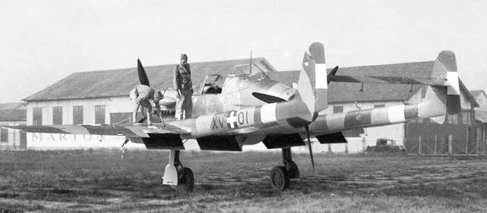
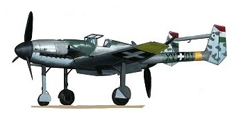
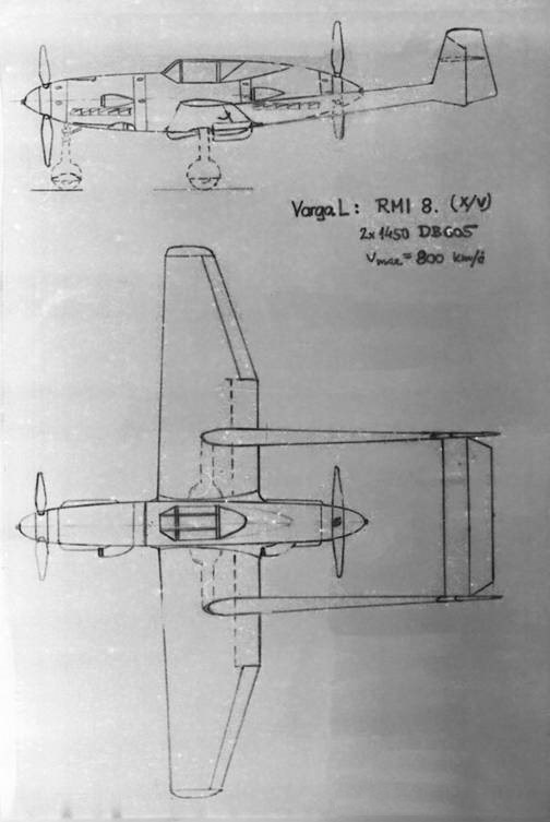
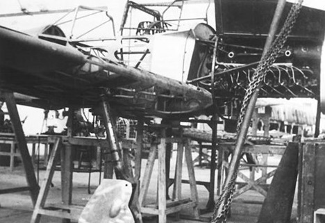
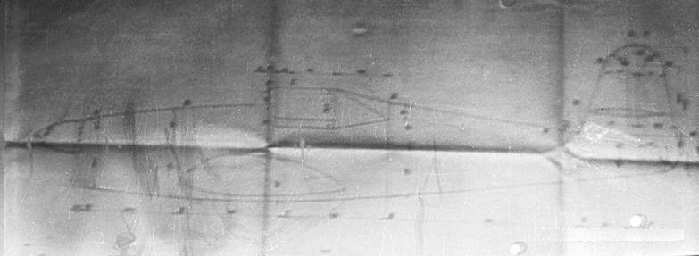
The RMI-8 X/V twin-boom, twin DB605 fighter was designed by Vilmos and Dezso Marton (assisted by László Varga), was also called the Marton X/V after the designers.
The two wings joined to the tail section, which is designed to incorporate the connection points of the high-powered MK-108 (30mm) deck gun.
The prototype (X/V-01) was said to have been destroyed by bombing while the airframe was still incomplete in April 1944.
Engines: 2 x DB-605, 1475 hp Wing span: 11.8m Length: 10.2m Height: 3.5m Empty weight: 2,850 kg T/O weight: 3,800 kg Maximum speed: 800 km/h Range: 1,000 km Ceiling: 11,500 m Armaments: 2 x 8 mm machine guns, 2 x 30mm MK-108 machine guns.
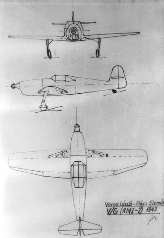
The RMI-7 V/G was a side-by-side trainer powered by an Argus As.410, and equipped with retractable undercarriage. The mixed wood-built machine with torsion wings and hydraulic main landing gear had the same structure as the RMI Z / G.
The V / G was designed from the start serial production. Designed by Varga László and Rácz Elemér, a prototype was built in 1944. In 1944 the prototype was shipped to the Budaörs airport in order to fly but possibly never flew.
Engine: Argus As.410 Wing span: 9.54m Length: 7.81m Height: 2.5m Empty weight: 1,200 kg T/O weight: 1,680 kg Maximum speed: 360 km/h Range: 1,000 km Ceiling: 8,000m