The origins of Rotary Air Force South Africa. date back to 1943 when Bernard J. Haseloh hovered his first experimental helicopter at his shop in Ponoka, Alberta , Canada.
Mr. Haseloh was discouraged from building and testing amateur/experimental built helicopters, by the Government who felt that the technology for the power driven rotor system was too complex for the private individual.
To further complicate matters, at that time the Government had no regulations in place for amateur/experimental built helicopters.
Haseloh did have an experimental helicopter hovering in 1943.
The origins of Rotary Air Force South Africa date back to 1943 when Bernard J. Haseloh hovered his first experimental helicopter at his shop in Ponoka, Alberta, Canada.
Mr. Haseloh was discouraged from building and testing amateur/experimental built helicopters, by the Government who felt that the technology for the power driven rotor system was too complex for the private individual.
To further complicate matters, at that time the Government had no regulations in place for amateur/experimental built helicopters. Therefore, his keen interest in Rotary Winged Aircraft turned toward the development of gyroplanes, the first of which was successfully completed in 1954
Over 30 years, Bernard Haseloh has developed and implemented numerous design and structural innovations for gyroplanes.
Mr. Haseloh has logged more than 2000 hours of flying time on his experimental “HASELOH” designed machines and has spent over 10,000 hours in the development of prototype gyroplanes of “ THE TYPE “ manufactured and sold by Rotary Air Force South Africa.
Bernard Haseloh holds the first Gyro Pilot’s License issued in Canada and is widely recognized as a pioneer in the gyroplane industry. Mr. Haseloh is highly regarded by Federal Aviation Regulators having for many years served as the designated gyroplane instructor for Alberta, Canada. Bernard Haseloh served as a key technical advisor to the development, testing & design of the RAF 2000
1987 the Group forms Rotary Air Force Marketing Inc, First aircraft to go into production is the RAF 1000, recognizing the need for proper flight instruction and to meet the demand for a two place gyroplane the Rotary Air Force team introduces the Two place Gyroplane in 1989.
Incorporated in 1987, Rotary Air Force employed 16 people in 2001.
In May 2001, RAF announced that it would be expanding its activities into commercial applications, including agricultural spraying and paramilitary functions.
As of April 2, 2007, Rotary Air Force Marketing Inc. closes doors.
USA Ross Aircraft Corporation was established in New York and built RS-1 light monoplane in 1940; war stopped production plans. A new model, the RS-2L two-seater, powered by a Lycoming engine, was built in 1942.
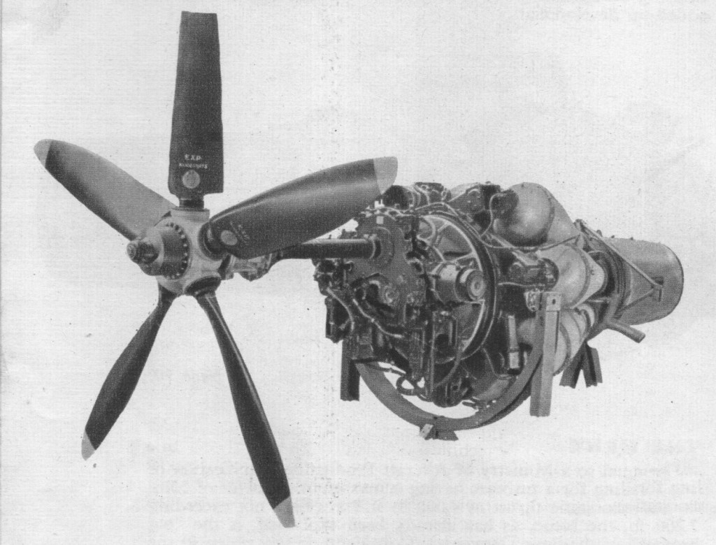
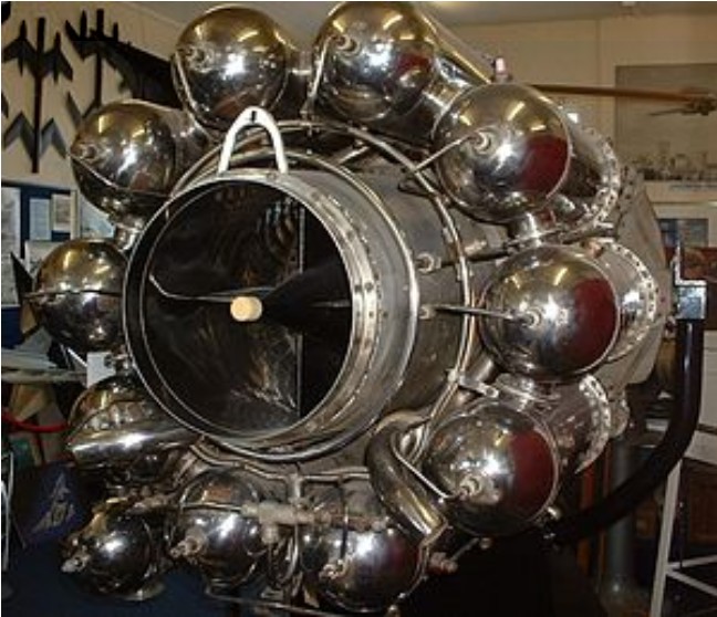
The Trent was based on a concept provided by Sir Frank Whittle and was essentially a Derwent Mark II turbojet engine with an additional turbine stage driving a reduction gearbox (designed by A A Rubbra) connected to a five-bladed Rotol propeller. Experimental work with the Trent (RB.50) actually dated back to May 1944, when a WelIand was equipped with a spur-type reduction gear and tested for shaft horsepower. First run in June 1944, the Trent ran for 633 hours on test before being installed in a Gloster Meteor (Trent Meteor) jet fighter which flew for the first time on 20 September 1945 at the start of a programme comprising 298 hours of flight tests.
The Rolls-Royce RB.50 Trent was the first Rolls-Royce turboprop engine.
Trent Type: Turboprop Dry weight: 1,000lb turbine unit, reduction gear 250lb, propeller 250lb, total engine/propeller weight 1,500lb Compressor: 1-stage double-sided centrifugal compressor Combustors: 10 x can combustion chambers Turbine: Single-stage axial Fuel type: Kerosene (R.D.E.F./F/KER) Oil system: pressure feed, dry sump with scavenge, cooling and filtration, oil grade 150 S.U. secs (32 cs) (Intavia 7106) at 38 °C (100 °F) Maximum power output: 750 shp, with 1,250 lb (570 kg) residual thrust
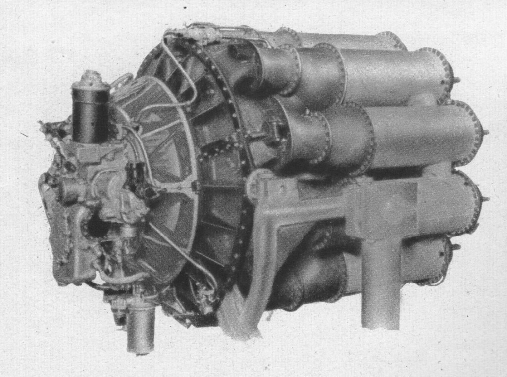
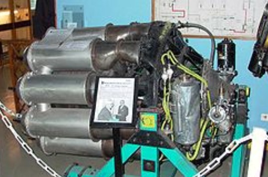
In 1940 the Air Ministry placed a contract with the Gloster Aircraft Company for prototypes of a new twin-engined jet fighter aircraft to the requirement of F.9/40, this aircraft became the Gloster Meteor. At the same time Power Jets was authorised to design a new engine that was intended to power the same aircraft. The W.2 was built under contract by the Rover Car Company in the early 1940s. It was originally intended to be produced by Rover as the W.2B/23.
The W.2 was basically a larger version of Whittle’s original flying design, the Whittle Supercharger Type W.1, or simply W.1, which flew in 1941 in the Gloster E. 28/39 experimental testbed aircraft. The engines used a single double-sided centrifugal compressor, or impeller, with the compressed air being taken off at several ports around the extreme outer edge of the compressor disk. They both used Whittle’s “reverse flow” design, in which the flame cans (combustion chambers) were placed around the turbine to produce a shorter engine. This required the heated air to flow forward before reversing its direction to pass through the single-stage axial-flow turbine. For the W.2, the impeller was 19 inches (480 mm) in diameter and there were ten flame cans. Air was bled from the compressor and fed into the inner portion of the turbine for cooling. The entire engine weighed about 850 pounds (390 kilograms).
Whittle was constantly frustrated by Rover. He thought that that there was an inability to deliver production-quality parts, and became increasingly vocal about his complaints. Whittle accused Rover of “tampering” with the design of the engine in order to avoid patent fees and enable Rover to claim the design as their own, whilst Rover’s development work was proceeding at a slow pace. Rover was losing interest in the project after the delays and constant harassment from Whittle. Earlier, in 1940, Stanley Hooker of Rolls-Royce had met Whittle, and later introduced him to Rolls’ CEO, Ernest Hives. Rolls had a fully developed supercharger division, which Hooker directed, which was naturally suited to jet engine work. Hives agreed to supply key parts to help the project along. Eventually, in early 1943, Spencer Wilks of Rover met Hives and Hooker, and decided to trade the jet factory at Barnoldswick for Rolls’ Meteor tank engine factory in Nottingham. A handshake sealed the deal.
Power Jets W.2/700
Active interest in jet propulsion was first shown by Rolls-Royce during 1938, when a department was established for the design of gas turbines. In 1939 the first projects were put in hand, and by 1940 test rigs for components had been set up. Towards the end of that year the company was making components for Whittle units on behalf of Power Jets, Ltd., and was undertaking the manufacture of turbine blades, casings, pumps and other components.
During 1941 a special test plant was installed, with a Vulture to drive the compressors.
Rover handed over a total of 32 W.2B/23 engines to Rolls-Royce as well as four “straight-through” W.2B/26 engines, developed by Rover’s Adrian Lombard. Rolls-Royce named their engines, and the continuous flow of air through the jets inspired Hooker to name them after the flow of British rivers. The W.2B/23 became the RB.23 Welland (RB standing for Rolls Barnoldswick), and the W.2B/26 became the RB.26 Derwent. Adrian Lombard moved with the engines from Rover to Rolls-Royce. Stanley Hooker helped in the task of ironing out the remaining problems, and things soon improved. A flight-quality /23 was fitted to a Gloster G.40, an updated version of the E.28 that had flown the W.1, and was flown by John Grierson on 1 March 1943. Starting in April, the ratings had been improved to 1,526 lbf (6.79 kN) thrust, and passed a run at 1,600 lbf (7.1 kN) on 7 May 1943. The prototype F.9/40 was finally fitted with 1,700 lbf (7.6 kN) engines and was flown by Michael Daunt on 24 July 1943.
The first Rolls-Royce turbojet, known as the WR1, measured 54in in diameter and was designed for a thrust of 2,000 lb. Built primarily to demonstrate that the aircraft gas turbine could be made cornpletely reliable, it ran for some 35 hr. Two examples were built, but combustion trouble was experienced.
Rolls-Royce there upon assumed control of the W.2 project, with Frank Whittle and his small team at Power Jets acting in an advisory capacity. Together, they ironed out the problems with the W.2 and finally put the engine into mass production as the 1600lbf thrust Rolls-Royce Welland. These engines were installed in the Gloster Meteor F Mk1 and early F Mk3’s and entered service in 1944.
Early in 1943 Rolls-Royce took over research on the W2B/23 unit from the Rover company, whose engineers had developed straight-through combustion; units of the type were installed in the Gloster E.28/39 experimental aircraft, and in the tails of two Vickers-Armstrongs Wellingtons. Like the earlier Power Jets W.1, the trombone configuration featured a simple double-sided centrifugal compressor, reverse-flow combustion chambers and an air-cooled axial-flow turbine section. The first Rolls-Royce/Whittle W2B/23 passed its 100-hr type-test in April 1943, and was given the name Welland; in June 1943 two were fitted in the Gloster F.9/40 (prototype of the Meteor), and by May 1944 Wellands were being regularly delivered for R.A.F. Meteors. The Welland had a reverse-flow combustion system, a maximum diameter of 43in and could develop 1,700 lb, although for the F9/40 it was at first derated to 1,450 lb.
Rolls-Royce Welland
The Halford H1 development was not held up like the W2/B hence it powered the the first Meteor to fly on the 5th March 1943 beating the Rover W2/B 23 powered DG205 by a week.
The first examples produced by Rover had serious problems with “surging”, in which the speed of the engine would suddenly increase out of control. Maurice Wilks eventually delivered a solution, by adding a set of 20-vane diffusers to the exhaust area. This solved the surging, but they now found that they had serious problems with the turbines failing, due to heat. J.P. Herriot of the Air Inspection Department (A.I.D.) was sent to Rover to provide improved turbine materials, and soon the engine achieved a 25-hour test at 1,250 lbf (5.6 kN) in November 1942. Meanwhile, the prototype Gloster F.9/40, soon to be known as the Meteor, was ready for flight, although the engines were not. Taxi tests were started by test pilot Jerry Sayer while the flight-quality engines waited. A real flight-test of the engine itself took place on 9 August 1942, fitted in the tail of a Vickers Wellington bomber.
Two Wellands were installed in the first production Meteor Mk.1, Serial number EE210/G, (the “/G” signifying “Guard”, meaning that the aircraft was to have an armed guard at all times while on the ground) which was test flown by Daunt on 12 January 1944. This Meteor was then sent to the US in exchange for a General Electric J31 (Power Jets W.1) powered Bell XP-59A Airacomet, RG362/G. The Meteor was first flown at Muroc Army Airfield by John Grierson on 15 April. Several test flights followed, and by December it had been shipped back to the UK. Production of the Meteor continued, with EF211 to 229 and 230 through 244 entering service No. 616 Squadron RAF in May 1944. The Wellands were rated at 1,600 lbf (7.1 kN), with 180 hours between overhauls. The Jumo 004B, which entering service only a few weeks earlier, was rated at 1,984 lbf (8.8 kN), but required overhaul after 10–20 hours. Flying from RAF Manston, near the English Channel, the 616 first saw action against the V-1 flying bombs en route to London on 27 July 1944.
From October 1943 a total of 167 Wellands were dispatched from the Rolls-Royce facility at Barnoldswick. By this point, Adrian Lombard’s straight-through design, which became the Rolls-Royce Derwent, had proved to be both more reliable and somewhat more powerful, and production of the Welland ended.
Variants:
W.2 Design thrust of 1600 lbf and a dry weight of approximately 850lb. Early versions could not exceed 1000lbf thrust without compressor surge.
W.2Y Direct flow combustion chamber design, May 1940, unbuilt.
W.2B Rover developed unit.
W.2/700 New compressor diffuser, improved compressor rotor and a static thrust of 2,000 lbf at 16,700 rpm.
W.2/800
W.2/850 A developed version of greater thrust of 2,485 lbf (1,127 kgf) at 16,500 rpm and a higher dry weight of 950lb (431 kg).
Rolls-Royce Welland Mass produced version of the W.2. Developed 1600lbf static thrust. 167 built
Applications: The following aircraft were used for test purposes only: Gloster E.28/39 F.9/40 Vickers Wellington
Production aircraft: Gloster Meteor
The W.2B/700 was to be used in the Miles M.52 supersonic research aircraft. In order to achieve the thrust required for supersonic flight, a version of the engine was developed using a turbine-driven “augmenter” ducted fan (an early form of turbofan). The NO.4 augmenter was mounted behind the engine, drawing fresh air through ducts surrounding the engine. Power was boosted even further by supplying the air to the world’s first “reheat jetpipe” or afterburner which was actually a very early athodyd or ramjet. The hope was that this combination of the W.2/700, turbofan augmenter and re-heat/ramjet would produce the required power for the proposed 1,000mph aircraft.
The Rolls-Royce Peregrine was a 21-litre (1,300 cu in), 885-horsepower (660 kW) liquid-cooled V-12 aero engine designed and built by Rolls-Royce in the late 1930s. First run in 1938, the Peregrine was developed during 1939 from the Kestrel. Running on 87 octane fuel, it had an international rating of 860 h.p. at 2,850 r.p.m. at 13,500 ft, and a maximum output of 885 h.p. at 3,000 r.p.m. at 15,000 ft. A number of Merlin features were incorporated and provision was made for a wide range of auxiliaries. External differences from the Kestrel included the fitting of a downdraught carburettor; this had progressive boost control, in which the “dead” range of movement of the throttle lever was eliminated.
During the 1930s the use of superchargers to increase “effective displacement” of an aircraft engine came into common use. Charging of some form was a requirement for high-altitude flight, and as the strength of the engines improved there was no reason not to use it at all times. The introduction of just such a “ground-level” supercharger to the Kestrel along with several design changes improved the power-to-weight ratio considerably, and it was generally felt that the resulting Peregrine would be the “standard” fighter engine for the impending war. Following the company convention of naming its piston aero engines after birds of prey, Rolls-Royce named the engine the Peregrine after the Peregrine Falcon (Falco peregrinus), the world’s fastest and most widespread bird of prey.
Although the Peregrine appeared to be a satisfactory design, it was never allowed to mature since Rolls-Royce’s priority was refining the Merlin. As a result, the Peregrine saw use in only two aircraft: the Westland Whirlwind and the Gloster F9/37.
A design feature of the Peregrine was that it was produced in both right- and left-hand tractor variants. This was done to improve aircraft handling by providing a counter-rotating propeller facility. The handing of internal parts to achieve this was a considerable complication that was later abandoned in favour of an idler gear arrangement for the Merlin propeller reduction gear.
Four Kestrel/Peregrine cylinder banks attached to a single crankcase and driving a single common crankshaft would produce the contemporary Rolls-Royce Vulture, a 1,700-horsepower (1,300 kW) X-24 which would be used for bombers.
As it transpired, aircraft designs rapidly increased in size and power requirements to the point where the Peregrine was simply too small to be useful. Although the Peregrine appeared to be a satisfactory design, it was never allowed to mature since Rolls-Royce’s priority was refining and producing the Merlin. As a result the Peregrine saw use in only two aircraft: the Westland Whirlwind and the Gloster F9/37, but proved unreliable in service. With the Merlin itself soon pushing into the 1,500 horsepower (1,100 kW) range, the Peregrine and Vulture were both cancelled in 1943, and by mid-1943 the Merlin was supplemented in service by the larger Rolls-Royce Griffon.
The two aircraft types that used the Peregrine, the Westland Whirlwind and the second prototype of the Gloster F9/37, were both twin-engine designs – the prototype F9/37 had used the Bristol Taurus radial engine. The Air Ministry requirement for the F9/37, a cannon-armed fighter (the Hurricane and Spitfire were armed with machine guns only at this point), was curtailed and there was no further progress with the design. The Whirlwind, despite having excellent low-altitude performance, proved uneconomical compared with single-engined fighters, and also suffered as a consequence of the Peregrine reliability problems. Low production rates of the Peregrine caused delays in delivery to squadron use. In August 1940 Ernest Hives, head of the Rolls-Royce aero engine division, wrote to Air Chief Marshal Wilfrid Freeman expressing his wish to stop work on the Peregrine, Vulture and another engine development project, the Rolls-Royce Exe to concentrate efforts on the Merlin and Griffon, but Freeman disagreed and stated that Peregrine production should continue.
While reliability problems were not uncommon for Rolls-Royce’s new engine designs of the era, the company’s testing department was told to spend all of their time on developing the more powerful Merlin to maturity. As a result of the Merlin’s priority, the unreliable Peregrine was eventually abandoned with production ending in 1942. Other cannon-armed fighters, such as the Hawker Typhoon and the Bristol Beaufighter, were becoming available; and since the Whirlwind had been tightly designed around the Peregrine, changing to a different engine at this stage was not, therefore, a feasible option. Only 116 Whirlwinds and a corresponding number of Peregrines (301) were built.
Peregrine I Type: 12-cylinder supercharged liquid-cooled 60-degree Vee aircraft piston engine Bore: 5 inches (127 mm) Stroke: 5.5 inches (140 mm) Displacement: 1,296 in³ (21.2 L) Length: 73.6 in (1,869 mm) Width: 27.1 in (688 mm) Height: 41.0 in (1,041 mm) Dry weight: 1,140 lb (517 kg) Valvetrain: Overhead camshaft Supercharger: Gear-driven single-speed centrifugal type supercharger, +9 psi boost Fuel system: Downdraught carburettor Fuel type: Petrol Cooling system: Liquid cooled, 70% water/30% ethylene glycol Power output: 885 hp (660 kW) at 3,000 rpm, +9 psi boost Specific power: 0.68 hp/in³ (31.1 kW/L) Compression ratio: 6:1 Power-to-weight ratio: 0.77 lb/hp
Rolls-Royce started planning its future aero engine development programme and realised there was a need for an engine larger than their 21-litre (1,296 cu in) Kestrel which was being used with great success in a number of 1930s aircraft. Consequently, work was started on a new 1,100 hp (820 kW)-class design known as the PV-12, with PV standing for Private Venture, 12-cylinder, as the company received no government funding for work on the project.
Drawings for the P.V.12 engine, as the Merlin was originally called, were begun in January 1933. When the first example was run on October 15th, a number of weaknesses were revealed, and it was not until July 1934 that a 100-hr type-test could be completed. This first unit gave 625 h.p. at 2,500 r.p.m. for take-off, and 790 h.p. at 12,000 ft. Rated boost was plus 2 lb, and weight 1,177 lb.
Early bench tests resulted in persistent cracking of cylinder jackets and failures of the double-helical reduction gear. The substitution of straight spur-gears cured the reduction-gear trouble, but strengthening of the big integral cylinder blocks and top half of the crankcase was not regarded as the complete answer to the cylinder-jacket defects. Experiments with different types of cylinder heads were made, and the integral cylinder block and upper half of the crankcase were replaced by separate castings for the two components.
An attempt in 1935 to pass a 50-hr civil type-test with the Merlin C (as the engine incorporating these changes was called) ended in failure, and it was not until December of that year that the test was completed. The rating was 955 b.h.p. at 2,600 r.p.m. at 11,000 ft, with a maximum output of 1,045 b.h.p. at 3,000 r.p.m. at 12,000 ft, and the engine (Merlin F) was put into production as the Merlin I.
In September 1937 Flight published the first description of the Mks I and II, remarking that engines of this series had then flown for over 2,000 hr and that they had shown a marked superiority over the early Kestrels in respect of the rough treatment they would stand. It was disclosed that the chief difference between the Merlin I and II (formerly Merlin G) lay in the cylinder heads. Whereas in the Merlin I these were of the detachable “ramp” type, the Merlin II had blocks and heads cast in a unit, following earlier practice. Both models had four valves per cylinder, each with two concentric return springs. There were two sodium-cooled exhaust valves on the outside of the head and two inlet valves on the inside. On the Merlin II all four were parallel to the centre-line of the block, but the two inlet valves in the detachable head of the Merlin I were inclined at about 45 deg to the exhaust valves. In both engines the latter had phosphor-bronze guides, and high-silicon-chrome steel scatings were screwed into the heads.
A fixed-datum automatic boost regulator maintained a constant induction-pipe pressure without continual reference to the boost gauge and throttle adjustment.
The hollow crankshafts were carried in seven special lead-bronze bearings, and the reduction gear was of 0.477: 1 ratio. Half the casing for the gearing was cast integrally with the crankcase; in this respect the Merlin differed from the Kestrel. Oil pumps carried on the lower half of the crankcase took their drive from the wheelcase through an idler gear. The dry-sump system was employed, and two scavenge pumps drained the front and rear ends of the crankcase. The pistons and the floating steel gudgeon-pins, which had phosphor-bronze bushes, were splash lubricated, a baffle in the lower half of the crankcase preventing excess oiling.
Sandwiched between the supercharger and the crankcase at the rear of the engine was a wheelcase from which a full complement of drives was taken. The Rolls-Royce/S.U. carburettor was of the twin-choke tube, updraught type, with a separate diffuser to each choke placed at right angles to the airstream. The semi-automatic, two-stage mixture-control device ‘was operated by air intake pressure, boost and/or a cockpit lever.
International power of the Merlin I and II was 950/990 h.p. at 2,600 r.p.m. at 12,250ft, and the maximum take-off output was 890 h.p. at 2,850 r.p.m.
When some of the first figures for the Merlin were published in Flight during May 1937, a note was appended on the development by Rolls-Royce, Ltd., of compact “power plant” assemblies, wherein the mounting was arranged to permit the radiator being carried close to the crankcase. Moreover, by mounting the header tank round the nose of the reduction gear the amount of piping was reduced to a minimum. Advantage was taken of then recent research in the reduction of cooling drag by enclosing the radiator in a low-drag cowling, wherein the cooling was done by air at relatively low velocity, and from which the flow through the matrix was controlled to suit various flight conditions by an adjustable flap at the exit.
A tribute was paid also to Rolls-Royce’s special experimental flight at Hucknall, where, on April 12th, 1935, a P.V.12 engine had first been flown in a Hawker Hart (serial number K3036).
The engine was originally designed to use the evaporative cooling system then in vogue. This proved unreliable and when supplies of ethylene glycol from the U.S. became available, the engine was adapted to use a conventional liquid cooling system. The Hart was subsequently delivered to Rolls-Royce where, as a Merlin testbed, it completed over 100 hours of flying with the Merlin C and E engines.
During June 1937 a Merlin II, mounted in a Horsley, began a 400-hr flight endurance test at Farnborough, and a specially rated “racing” engine was developed from it with a view to installation in the special Speed Spitfire, with which an attack on the world’s speed record was contemplated. The engine used was a Merlin III, which differed from the Merlin II in having a standardized de Havilland/Rotol airscrew shaft and dual accessory-drive. It was taken from stock and was fitted with strengthened pistons, gudgeon-pins and connecting rods to withstand the extra load. “The power output of the standard engine,” writes Harold Nockolds, “was 1,030 b.h.p. at 3,000 r.p.m. at 10,250ft with plus 6.25 lb boost. “Solely by opening the throttle, raising the supercharger pressure, and using fuel of a higher octane,” he goes on [the petrol normally used at that time was 87 octane], “the engine was made to develop no less than 2,160 b.h.p. at 3,200 r.p.m. with the supercharger giving 27 lb/sq in boost. Ibis was a phenomenal performance, for it meant that a power to-weight ratio of 0.621 lb per horsepower had been achieved a considerable improvement on the 0.71 lb per horsepower of the 1931 R engine.
This output was only attained for a short period, but Elliott and Hives were perhaps even more satisfied with a 15-hr endurance run at 1,800 b.h.p., 3,200 r.p.m. and 22 lb boost accomplished during the development period. After this they felt perfectly satisfied that the Merlin would be capable of meeting all the demands that might be made of it.
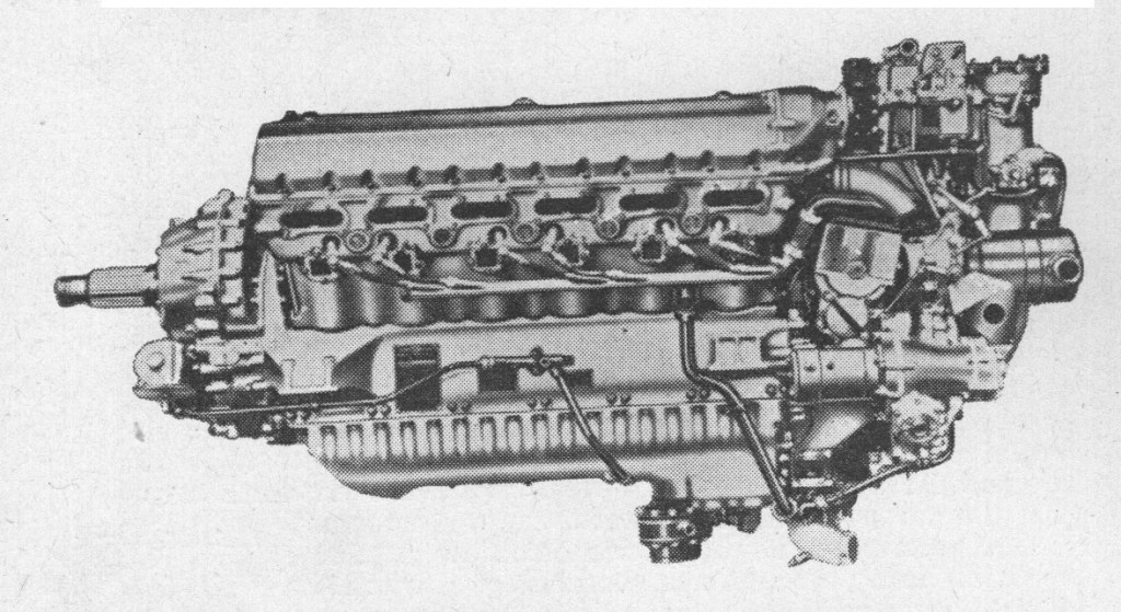
The Merlin II and III were installed in the Spitfire I, Defiant I, Hurricane I, Sea Hurricane I, and Battle I, and were-as will always be remembered-vital factors in the winning of the Battle of Britain. The Merlin III was the first version to incorporate a “universal” propeller shaft, allowing either de Havilland or Rotol manufactured propellers to be used. The Merlin IV had pressure-water cooling in place of the glycol cooling of the earlier models, and was developed for installation in the Armstrong Whitworth Whitley IV bomber. The Mk VIII, installed in the Fairey Fulmar I, was a medium supercharged unit rated at 1,010 h.p. at 2,850 r.p.m. at 6,750 ft, and, using 100-octane fuel, delivered 1,080 h.p. at 3,000 r.p.m. for take-off.
Rolls Royce Merlin III
The Merlin X-installed in the Halifax I, Wellington II and Whitley V and VII had a two-speed supercharger to improve take-off, low altitude performance during climb or level flight, and fuel economy under cruising conditions. The speed change was effected through an oil-pressure system, the actual changeover under full power taking about a second. In low gear the Merlin X gave 1,145 h.p. at 5,250 ft, and in high gear 1,010 h.p. at 17,750 ft.
Tne Merlin XII, driving a Rotol three-blade constant-speed airscrew, was installed in some Spitfire IIs; its maximum output was 1,150 h.p. at 3,000 r.p.m. at 14,000 ft and it had a 0.477:1 reduction gear.
The next production-type engine was the Merlin XX, which, compared with the X, delivered a greatly increased power at height. The two units were, however, interchangeable. The two-speed supercharger of the Merlin XX was of improved design, incorporating a modified form of central entry which gave a freer flow of air to the blower. The low-gear ratio was 8.15: 1 and the high gear 9.49: 1. Amendments were also made to the rotating and fixed guide vanes and the improvements mentioned, in conjunction with a larger, twin-choke, updraught S.U. carburettor (designed as a complete, separate unit), gave a marked increase in power. Thus, using 100-octane fuel, the international rating in low gear was 1,240 h.p. at 2,850 r.p.m. at 10,000 ft and plus 9 lb/sq in boost; in high gear the figure was 1,175 h.p. at 2,850 r.p.m. at 17,500 ft, again at plus 9 lb boost. The achievement of extracting so much extra power from a given cubic capacity had increased the dry weight by only 75 lb, and that over 100 h.p. were being taken from each cylinder. The Merlin XX powered the Beaufighter II, Defiant II, Halifax II and V, Hurricane II and IV, and Lancaster I and III.
Merlins 21, 22, 23, 24 and 25 were all essentially similar to the Merlin XX. The 21 was fitted in the Mosquito I, II, III, IV and VI; the 22 in the Lancaster I and II and the York I; the 23 in the Mosquito I, II, IV, VI, XII and XIII; the 24 in the Lancaster I and III and York I; and the 25 in the Mosquito VI and XIX. Take-off power of the 24 and 25 was 1,620 h.p.
The Merlin 28 was a Packard-built engine, installed in the Lancaster I and III and the Kittyhawk II and known in America as the V-1650-1. When it was disclosed in Great Britain that this American-built engine would differ from its British equivalent in having detachable cylinder heads, it was explained that this form of construction had already been proved satisfactory by Rolls-Royce, Ltd., and would have been adopted by them two years or more previous to the Packard innovation had it not been for the fact that such an important modification would have delayed the attainment of maximum production.
The Merlin 29 was also Packard-built, but had a reduction gear ratio of 0.477 : 1 instead of 0.42 : 1, and was fitted with a splined airscrew shaft; it was fitted in Canadian-built Hurricanes and the Kittyhawk II. Changes from its predecessor were so small that the designation V-1650-1 was retained.
The Merlin 30 was a medium-supercharged engine, installed in the Barracuda I and Fulmar II, and giving 1,240 h.p. at 7,250 ft and a take-off output of 1,300 h.p. The Merlin 31 was another Packard V-1650-1 and was mounted in the Canadian Mosquito XX, the Australian Mosquito 40, and the Kittyhawk II. An increase in take-off output from 1,300 h.p. to 1,600 h.p. characterized the Merlin 32, which powered the Barracuda II and Seafire II. The Merlin 33 was yet another Packard-built version, installed in the Mosquito XX and 40, and the 38 (also by Packard) was fitted in the Lancaster I and III. Both the 33 and 38 gave 1,390 h.p. for take-off.
A variant which saw very extensive service was the Merlin 45, fitted in the Spitfire V, P.R.IV and VII, and Seafire II; at 16,000 ft and 2.850 r.p.m. its output was 1,200 h.p. The Merlin 45M was rated for duty at lower levels and delivered 1,585 h.p. at 2,750 ft; it was fitted in the Spitfire L.F.V. The Merlin 46 and 47 were both high-altitude engines (1.115 h.p. at 19,000 ft); the 46 powered the Spitfire V, P.R.IV and VII, and Seafire I, and the 47 (which bad a cabin supercharger) found its application in the Spitfire VI. The Merlin 50 was similar to the 45 and was fitted in the Spitfire V; the 50M was almost identical with the 45M and powered the Spitfire L.F.V; the 55 was again like the Merlin 45 and was fitted in the Spitfire V and Seafire III; and the 55M resembled the 45M and was the power unit of the Spitfire L.F.V and Seafire L.F Ill.
In March 1940 Rolls-Royce had been asked by the Ministry of Aircraft Production to submit their proposals for increasing the high-altitude output of the Merlin to enable a pressurized development of the Wellington to operate at 40,000 ft. An output of 800 h.p. at 40,000 ft was estimated to be required. To that end the company set about experimenting with a two-stage supercharger, and an engine with this fitment was bench-tested in April 1941. This became the Merlin 60, which, though installed in Wellington VIs, was soon declared obsolete. Adapted for fighter requirements, however, and designated Merlin 61, the new engine was installed in the Spitfire VII, VIII. IX. and P.RXI, and gave those fighters an edge over their German adversaries.
The key feature of the Merlin 61 was its two-speed, two-stage supercharger, with two rotors on a common shaft. The mixture was compressed by the first stage and was delivered to the inlet of the second stage, where it was further compressed before being delivered to the induction pipe. In order to reduce the mixture temperature to a normal figure, a box-like intercooler was interposed between the outlet of the second-stage supercharger and the rear of the cylinder blocks. In a typical Spitfire installation the intercooler radiator was mounted under the port wing in a duct, which also housed one of the main engine-cooling radiators.
The real significance of the Merlin 61 was that at 40,000 ft it developed double the power given at a much lower altitude by the Merlin II of 1939/40. Even at 23,500 ft its maximum power was 1,390 h.p. The weight had risen to 1,640 lb.
Merlin consumed an enormous volume of air at full power (equivalent to the volume of a single-decker bus per minute), and with the exhaust gases exiting at 1,300 mph (2,100 km/h) it was realised that useful thrust could be gained simply by angling the gases backwards instead of venting sideways.
During tests, 70 pounds-force (310 N; 32 kgf) thrust at 300 mph (480 km/h), or roughly 70 horsepower (52 kW) was obtained which increased the level maximum speed of the Spitfire by 10 mph (16 km/h) to 360 mph (580 km/h). The first versions of the ejector exhausts featured round outlets, while subsequent versions of the system used “fishtail” style outlets which marginally increased thrust and reduced exhaust glare for night flying.
In September 1937 the Spitfire prototype, K5054, was fitted with ejector type exhausts. Later marks of the Spitfire used a variation of this exhaust system fitted with forward-facing intake ducts to distribute hot air out to the wing-mounted guns to prevent freezing and stoppages at high altitudes, replacing an earlier system that used heated air from the engine coolant radiator. The latter system had become ineffective due to improvements to the Merlin itself which allowed higher operating altitudes where air temperatures are lower. Ejector exhausts were also fitted to other Merlin-powered aircraft.
Merlin 61 components:
Cylinders Twelve cylinders consisting of high-carbon steel liners set in two, two-piece cylinder blocks of cast “R.R.50” aluminium alloy having separate heads and skirts. Coolant in direct contact with external face of liners. Cylinder heads fitted with cast-iron inlet valve guides, phosphor bronze exhaust valve guides, and renewable “Silchrome” steel-alloy valve seats. Two diametrically opposed spark plugs protrude into each combustion chamber.
Pistons Machined from “R.R.59” alloy forgings. Fully floating hollow gudgeon pins of hardened nickel-chrome steel. Three compression and one oil-control ring above the gudgeon pin, and one oil-control ring below.
Connecting rods H-section machined nickel-steel forgings, each pair consisting of a plain and a forked rod. The forked rod carries a nickel-steel bearing block which accommodates steel-backed lead-bronze-alloy bearing shells. The “small-end” of each rod houses a floating phosphor bronze bush.
Crankshaft One-piece, machined from a nitrogen-hardened nickel-chrome molybdenum steel forging. Statically and dynamically balanced. Seven main bearings and six throws.
Crankcase Two aluminium-alloy castings joined together on the horizontal centreline. The upper portion bears the wheelcase, supercharger and accessories; and carries the cylinder blocks, crankshaft main bearings (split mild-steel shells lined with lead bronze alloy), and part of the housing for the airscrew reduction gear. The lower half forms an oil sump and carries the oil pumps and filters.
Wheelcase Aluminium casting fitted to rear of crankcase. Houses drives to the camshafts, magnetos, coolant and oil pumps, supercharger, hand and electric starters, and the electric generator.
Valve gear Two inlet and two exhaust poppet valves of “K.E.965” steel per cylinder. Both the inlet and exhaust valves have hardened “stellited” ends; while the exhaust valves also have sodium-cooled stems, and heads protected with a “Brightray” (nickel-chromium) coating. Each valve is kept closed by a pair of concentric coil-springs. A single, seven-bearing camshaft, located on the top of each cylinder head operates 24 individual steel rockers; 12 pivoting from a rocker shaft on the inner, intake side of the block to actuate the exhaust valves, the others pivoting from a shaft on the exhaust side of the block to actuate the inlet valves.
The Merlin 62.was used in the Wellington VI, and the 63 (wherein the maximum output had risen to over 1,650 h.p.) appeared in the Spitfire VII, VIII, IX and P.R.XL The 64 was similar to the 63 but had a cabin supercharger; it was mounted in the Spitfire VII. The 66 powered the Spitfire L.F.VIII and IX. The 67 had a reduction gear of 0.42: 1 instead of 0.477: 1, as had the 63, 64 and 66, and the 68 was a Packard-built model, designated V-1650-3 and installed in the Mustang Ill. Its takeoff output was 1,400 h.p. In the Merlin 69-another Packard built variant, known in America as the V-1650-7, 1,490 h.p. was available for take-off; this engine powered Mustang IIIs and IVs. The Merlin 70 appeared in the Spitfire H.F.VIII and IX and P.RXI, and the 71 (with cabin blower) in the Spitfire H.F.VII. The Merlin 72 was applied to the Mosquito P.R.IX, XVI and 30, and the Westland Welkin I. Some Mosquito XVIs and Welkin Is had Merlin 73s or 76s. The 76 was the same as the 72, but had a cabin supercharger. Yet another engine for the Mosquito XVI and Welkin I was the 77, with cabin supercharger. In the Merlin 85 the take-off output was increased to 1,635 h.p. This was a bomber engine and was installed in the Lancaster VI and Lincoln I. The Merlin 224 was built by Packard and was the same as the Merlin 24; it was fitted in the Lancaster I and Ill. The 225 was another Packard-built model used in the Mosquito 25 and 26 and identical with the Merlin 25. The Merlin 266-again Packard-built-was the same as the Merlin 66 and was mounted in the Spitfire L.F.XVI.
The war being over, and the exigencies of security less restrictive, particulars were released of the Merlin 113 and 114, which became well known as the power plants of Mosquitoes 34, 35 and 36. These engines delivered 1,430 h.p. at 27,250 ft with a boost pressure of plus 18 lb. Even more notable were the Merlin 130 and 131, specially “tailored” for the de Havilland Hornet.
The Merlin 130 and 131 were the first of their family to incorporate down-draught carburettors; and, to eliminate the air scoop as used on the Mosquito, ducted air intakes were faired into the leading edges of the wing. The war-time Bendix/Stromberg carburettor was replaced by a low-pressure fuel-injection system, which delivered through a spray nozzle into the supercharger eye. The 130/131 differed only in being “handed” right and left respectively. The sum total of improvements incorporated in these remarkable engines raised the output to 2,030 h.p. at 1,250 ft with a boost of plus 25 lb/sq in. Ultimately, during tests conducted by Rolls-Royce at Derby, Merlin 130 series engines generated over 2,600 horsepower (1,940 kW).
Another special military Merlin of the post-war years was the 140, developed for the Short Sturgeon and equipped to drive contra-rotating airscrews. Emergency maximum power was 1,650 h.p. at 16,750 ft.
The Merlin to go into service with the R.A.F. and Royal Navy is the 35, a trainer engine developed for the Avro Athena and Boulton Paul Balliol. It has a single-speed supercharger and a maximum take-off output of 1,280 h.p.
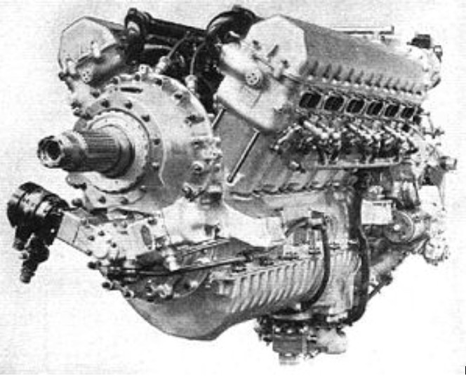
The Merlin engine achieved in post-war years a record in the civil field. The first of the civil Merlins, the 102, was the first to complete successfully the Air Registration Board’s type-test requirements for civil aero engines. There followed the 500 series (these were installed in Lancastrians and Yorks), with two-speed, single-stage supercharger, and the 600 series, with two-speed, two-stage supercharger. The 620 was designed specifically for North Atlantic operation and went into service during 1947 in the Canadair North Star airliners of T.C.A. The 600, 620 and 621 series deliver a continuous cruising power of 1.160 h.p. at 23,500ft and 1,725 h.p. for take-off; the 622-626 units have a continuous cruising rating of 1,420 h.p. at 18,700 ft, and give 1,760 h.p. for take-off.
There are numerous variations between the civil Merlins; thus, the 621 has half intercooling and charge heating; the 722 either full or no intercooling; the 623 half intercooling and charge heating; and the 724 and 724-1C either full or no intercooling. Installations include: Merlin 621, Avro Tudor II and IV; 722, T.C.A. Canadair North Star; 623, Tudor IVB and V; 724, T.C.A. North Star; 724-1C, B.O.A.C. Argonaut (Canadair Four).
Merlin 621
Central to the success of the Merlin was the supercharger. A.C. Lovesey, an engineer who was a key figure in the design of the Merlin, delivered a lecture on the development of the Merlin in 1946; in this extract he explained the importance of the supercharger:
“Coming now to specific development items we can … divide them into three general classes:
1.Improvement of the supercharger. 2.Improved fuels. 3.Development of mechanical features to take care of the improvements afforded by (1) and (2). Dealing with (1) it can be said that the supercharger determines the capacity, or … the output, of the engine. The impression still prevails that the static capacity known as the swept volume is the basis of comparison of the possible power output for different types of engine, but this is not the case because the output of the engine depends solely on the mass of air it can be made to consume efficiently, and in this respect the supercharger plays the most important role … the engine has to be capable of dealing with the greater mass flows with respect to cooling, freedom from detonation and capable of withstanding high gas and inertia loads … During the course of research and development on superchargers it became apparent to us that any further increase in the altitude performance of the Merlin engine necessitated the employment of a two-stage supercharger.” As the Merlin evolved so too did the supercharger; the latter fitting into three broad categories:
1.Single-stage, single-speed gearbox: Merlin I to III, XII, 30, 40, and 50 series (1937–1942).[nb 4] 2.Single-stage, two-speed gearbox: experimental Merlin X (1938), production Merlin XX (1940–1945). 3.Two-stage, two-speed gearbox with intercooler: mainly Merlin 60, 70, and 80 series (1942–1946). The Merlin supercharger was originally designed to allow the engine to generate maximum power at an altitude of about 16,000 ft (4,900 m). In 1938 Stanley Hooker, an Oxford graduate in applied mathematics, explained “… I soon became very familiar with the construction of the Merlin supercharger and carburettor … Since the supercharger was at the rear of the engine it had come in for pretty severe design treatment, and the air intake duct to the impeller looked very squashed …” Tests conducted by Hooker showed the original intake design was inefficient, limiting the performance of the supercharger.[29][nb 5] Hooker subsequently designed a new air intake duct with improved flow characteristics which increased maximum power at a higher altitude of over 19,000 ft (5,800 m); and also improved the design of both the impeller, and the diffuser which controlled the airflow to it. These modifications led to the development of the single-stage Merlin XX and 45 series.
A significant advance in supercharger design was the incorporation in 1938 of a two-speed drive (designed by the French company Farman) to the impeller of the Merlin X. The later Merlin XX incorporated the two-speed drive as well as several improvements that enabled the production rate of Merlins to be increased. The low-ratio gear, which operated from take-off to an altitude of 10,000 ft (3,000 m), drove the impeller at 21,597 rpm and developed 1,240 horsepower (925 kW) at that height; while the high gear’s (25,148 rpm) power rating was 1,175 horsepower (876 kW) at 18,000 ft (5,500 m). These figures were achieved at 2,850 rpm engine speed using +9 pounds per square inch (1.66 atm) boost.
In 1940, after receiving a request in the March of that year from the Ministry of Aircraft Production for a high-rated (40,000 ft (12,000 m)) Merlin for use as an alternative engine to the turbocharged Hercules VIII used in the prototype high-altitude Vickers Wellington V bomber, Rolls-Royce started experiments on the design of a two-stage supercharger and an engine fitted with this was bench-tested in April 1941, eventually becoming the Merlin 60. The basic design used a modified Vulture supercharger for the first stage while a Merlin 46 supercharger was used for the second. A liquid-cooled intercooler on top of the supercharger casing was used to prevent the compressed air/fuel mixture from becoming too hot. Also considered was an exhaust-driven turbocharger but, although a lower fuel consumption was an advantage the added weight and the need to add extra ducting for the exhaust flow and waste-gates, meant that this option was rejected in favour of the two-stage supercharger. Fitted with the two-stage two-speed supercharger, the Merlin 60 series gained 300 horsepower (224 kW) at 30,000 ft (9,100 m) over the Merlin 45 series, at which altitude a Spitfire IX was nearly 70 mph (110 km/h) faster than a Spitfire V.
The two-stage Merlin family was extended in 1943 with the Merlin 66 which had its supercharger geared for increased power ratings at low altitudes, and the Merlin 70 series that were designed to deliver increased power at high altitudes.
While the design of the two-stage supercharger forged ahead, Rolls-Royce also continued to develop the single-stage supercharger, resulting in 1942 in the development of a smaller “cropped” impeller for the Merlin 45M and 55M; both of these engines developed greater power at low altitudes.[40] In squadron service the LF.V variant of the Spitfire fitted with these engines became known as the “clipped, clapped and cropped Spitty” to indicate the shortened wingspan, the less-than-perfect condition of the used airframes and the cropped supercharger impeller.
The use of carburettors was calculated to give a higher specific power output, due to the lower temperature, hence greater density, of the fuel/air mixture compared to injected systems. However, the Merlin’s float controlled carburettor meant that both Spitfires and Hurricanes were unable to pitch nose down into a steep dive. The contemporary Bf 109E, which had direct fuel injection, could “bunt” into a high-power dive to escape attack, leaving the pursuing aircraft behind because its fuel had been forced out of the carburettor’s float chamber by the effects of negative g-force (g). RAF fighter pilots soon learned to “half-roll” their aircraft before diving to pursue their opponents. “Miss Shilling’s orifice”, a holed diaphragm fitted across the float chambers, went some way towards curing the fuel starvation in a dive; however, at less than maximum power a “fuel rich” mixture still resulted. Another improvement was made by moving the fuel outlet from the bottom of the S.U. carburettor to exactly halfway up the side, which allowed the fuel to flow equally well under negative or positive g.
Further improvements were introduced throughout the Merlin range: 1943 saw the introduction of a Bendix-Stromberg pressure carburettor that injected fuel at 5 pounds per square inch (34 kPa; 0.34 bar) through a nozzle directly into the supercharger, and was fitted to Merlin 66, 70, 76, 77 and 85 variants. The final development, which was fitted to the 100-series Merlins, was an S.U. injection carburettor that injected fuel into the supercharger using a fuel pump driven as a function of crankshaft speed and engine pressures.
At the start of the war the Merlin I, II and III ran on the then standard 87 octane aviation spirit and could generate just over 1,000 horsepower (750 kW) from its 27-litre (1,650-cu in) displacement: the maximum boost pressure at which the engine could be run using 87 octane fuel was +6 pounds per square inch (141 kPa; 1.44 atm). However, as early as 1938, at the 16th Paris Air Show, Rolls-Royce displayed two versions of the Merlin rated to use 100 octane fuel. The Merlin R.M.2M was capable of 1,265 horsepower (943 kW) at 7,870 feet (2,400 m), 1,285 horsepower (958 kW) at 9,180 feet (2,800 m) and 1,320 horsepower (984 kW) on take-off; while a Merlin X with a two-speed supercharger in high gear generated 1,150 horsepower (857 kW) at 15,400 feet (4,700 m) and 1,160 horsepower (865 kW) at 16,730 feet (5,100 m).
From late 1939, 100 octane fuel became available from the U.S., West Indies, Persia and, in smaller quantities, domestically. Small modifications were made to Merlin II and III series engines, allowing an increased (emergency) boost pressure of +12 pounds per square inch (183 kPa; 1.85 atm). At this power setting these engines were able to produce 1,310 horsepower (977 kW) at 9,000 ft (2,700 m) while running at 3,000 revolutions per minute.[48][49] The increased boost was available for a maximum of five minutes and was considered a “definite overload condition on the engine”; if the pilot resorted to emergency boost he had to report this on landing, when it was noted in the engine log book, while the engineering officer was required to examine the engine and reset the throttle gate. Later versions of the Merlin ran only on 100 octane fuel and the five-minute combat limitation was raised to +18 pounds per square inch (224 kPa; 2.3 atm).
In late 1943 trials were run of a new “100/150” grade (150 octane) fuel, recognised by its bright-green colour and “awful smell”. Initial tests were conducted using 6.5 cubic centimetres (0.23 imp fl oz) of tetraethyllead (T.E.L.) for every one imperial gallon of 100 octane fuel (or 1.43 cc/L or 0.18 U.S. fl oz/U.S. gal), but this mixture resulted in a build-up of lead in the combustion chambers, causing excessive fouling of the spark plugs. Better results were achieved by adding 2.5% mono methyl aniline (M.M.A.) to 100 octane fuel. The new fuel allowed the five-minute boost rating of the Merlin 66 to be raised to +25 pounds per square inch (272 kPa; 2.7 atm).
Starting in March 1944, the Merlin 66-powered Spitfire IXs of two ADGB squadrons were cleared to use the new fuel for operational trials, and it was put to good use in the summer of 1944 when it enabled Spitfire L.F. Mk. IXs to intercept V-1 flying bombs coming in at low altitudes. 100/150 grade fuel was also used by Mosquito night fighters of the ADGB to intercept V-1s. In early February 1945, Spitfires of the 2 TAF also began using 100/150 grade fuel.
Production Production of the Rolls-Royce Merlin was driven by Ernest Hives, who at times was enraged by the apparent complacency and lack of urgency encountered in his frequent correspondence with Air Ministry and local authority officials. Hives was an advocate of shadow factories, and sensing the imminent outbreak of war pressed ahead with plans to produce the Merlin in sufficient numbers for the rapidly expanding Royal Air Force. Despite the importance of uninterrupted production several factories were affected by industrial action. By the end of its production run in 1950, almost 150,000 Merlin engines had been built; over 112,000 in Britain and more than 37,000 under licence in the U.S.
Derby The existing Rolls-Royce facilities at Osmaston, Derby were not suitable for large-scale engine production although the floor space had been increased by some 25% between 1935 and 1939; nevertheless, Hives planned to build the first two- or three hundred engines there until engineering teething troubles had been resolved. Having a workforce that consisted mainly of design engineers and highly skilled men, the Derby factory carried out the majority of development work on the Merlin, with flight testing carried out at nearby RAF Hucknall. The original factory closed in March 2008, but Rolls-Royce plc still maintains a large presence in Derby.
Crewe To meet the increasing demand for Merlin engines, Rolls-Royce started building work on a new factory at Crewe in May 1938, with engines leaving the factory in 1939. The Crewe factory had convenient road and rail links to their existing facilities at Derby. Production at Crewe was originally planned to use unskilled labour and sub-contractors with which Hives felt there would be no particular difficulty, but the number of required sub-contracted parts such as crankshafts, camshafts and cylinder liners eventually fell short and the factory was expanded to manufacture these parts “in house”.
Initially the local authority promised to build 1,000 new houses to accommodate the workforce by the end of 1938, but by February 1939 it had only awarded a contract for 100. Hives was incensed by this complacency and threatened to move the whole operation, but timely intervention by the Air Ministry improved the situation. In 1940 a strike took place when women replaced men on capstan lathes, the workers’ union insisting this was a skilled labour job; however, the men returned to work after 10 days. Post-war the factory was used for the production of Bentley motor cars, and in 1998 Volkswagen AG bought both the marque and the factory. Today it is known as Bentley Crewe.
Glasgow Hives further recommended that a factory be built near Glasgow to take advantage of the abundant local work force and the supply of steel and forgings from Scottish manufacturers. This government-funded and -operated factory was built at Hillington starting in June 1939 with workers moving into the premises in October, one month after the outbreak of war, the factory becoming fully occupied by September 1940. A housing crisis also occurred at Glasgow where Hives again asked the Air Ministry to step in.
Having 16,000 employees, the Glasgow factory was one of the largest industrial operations in Scotland. Unlike the Derby and Crewe plants which relied significantly on external subcontractors, it produced almost all the Merlin’s components itself. Engines began to leave the production line in November 1940, and by June 1941 monthly output had reached 200, increasing to more than 400 per month by March 1942. In total 23,675 engines were produced. Worker absenteeism became a problem after some months due to the physical and mental effects of wartime conditions such as the frequent occupation of air-raid shelters. It was agreed to cut the punishing working hours slightly to 82 hours a week, with one half-Sunday per month awarded as holiday. Record production is reported to have been 100 engines in one day.
Immediately after the war the site repaired and overhauled Merlin and Griffon engines, and continued to manufacture spare parts. Finally, following the production of the Rolls-Royce Avon turbojet and others, the factory was closed in 2005.
Manchester: Ford Trafford Park Factory Early in 1940 Ford of Britain was approached by Herbert Austin, who was in charge of the shadow factory plan, about the possibility of converting an abandoned factory in Trafford Park into an aircraft engine production unit. Construction of the new factory was started in May 1940 on a 118-acre (48 ha) site. During this time Ford engineers went on a fact finding mission to Derby, where their chief engineer commented to Sir Stanley Hooker that the manufacturing tolerances used by Rolls-Royce were far too wide for them. As a consequence over a year was taken up re-drafting 20,000 drawings to Ford tolerance levels.
Ford’s factory, which was completed in May 1941, was built in two distinct sections to limit potential bomb damage. At first, the factory had difficulty in attracting suitable labour, such that large numbers of women, youths and untrained men had to be taken on. Despite this the first Merlin engine came off the production line one month after the factory’s completion, and the production rate was 200 Merlins per week by 1943. Ford’s investment in machinery and the redesign resulted in the 10,000 man-hours needed to produce a Merlin dropping to 2,727 man-hours three years later, while unit cost fell from £6,540 in June 1941 to £1,180 by the war’s end. In his autobiography Not much of an Engineer, Sir Stanley Hooker states: “… once the great Ford factory at Manchester started production, Merlins came out like shelling peas. The percentage of engines rejected by the Air Ministry was zero. Not one engine of the 30,400 produced was rejected …”. Some 17,316 people worked at the Trafford Park plant, including 7,260 women and two resident doctors and nurses. Merlin production started to run down in August 1945, and finally ceased on 23 March 1946.
Packard V-1650 As the Merlin was considered to be so important to the war effort, negotiations were soon started to establish an alternative production line outside the UK. Rolls-Royce staff visited a number of North American automobile manufacturers in order to select one to build the Merlin in the U.S. or Canada. Henry Ford rescinded an initial offer to build the engine in the U.S. in July 1940, and the Packard Motor Car Company was subsequently selected to take on the $130,000,000 Merlin order. Agreement was reached in September 1940, and the first Packard-built engine, designated V-1650-1, ran in August 1941.
In 1942 Continental received a wartime contract for production of Rolls-Royce Merlin V-1650-3, -7, -9, and -17. A total of 897 were built.
More than 150,000 Merlins were built in Great Britain and the U.S.A. by the end of the war.
At the end of World War II, new versions of the Merlin (the 600- and 700-series) were designed and produced for use in commercial airliners such as the Avro Tudor, military transport aircraft such as the Avro York, and the Canadair North Star which performed in both roles. These engines were basically military specification with some minor changes to suit the different operating environment.
A Spanish-built version of the Messerschmitt Bf 109 G-2, the 1954 Hispano Aviación HA-1112-M1L Buchon, was built in Hispano’s factory in Seville with the Rolls-Royce Merlin 500/45 engine of 1,600 horsepower (1,200 kW).
The CASA 2.111 was another Spanish-built version of a German aircraft, the Heinkel He 111, that was adapted to use the Merlin after the supply of Junkers Jumo 211F-2 engines ran out at the end of the war. A similar situation existed with the Fiat G.59 when available stocks of the Italian licence-built version of the Daimler-Benz DB 605 engine ran short.
A non-supercharged version of the Merlin using a larger proportion of steel and iron components was produced for use in tanks. This engine, the Rolls-Royce Meteor, in turn led to the smaller Rolls-Royce Meteorite.
In 1938, Rolls-Royce started work on modifying some Merlins which were later to be used in British MTBs, MGBs, and RAF Air-Sea Rescue Launches. For these the superchargers were modified single-stage units and the engine was re-engineered for use in a marine environment.
Experiments were carried out by the Irish Army involving replacing the Bedford engine of a Churchill tank with a Rolls-Royce Merlin engine salvaged from an Irish Air Corps Seafire aircraft. The experiment was not a success, although the reasons are not recorded.
PV-12 The initial design using an evaporative cooling system. Two built, passed bench Type Testing in July 1934, generating 740 horsepower (552 kW) at 12,000-foot (3,700 m) equivalent. First flown 21 February 1935.
Merlin B Two built, ethylene glycol liquid cooling system introduced. “Ramp” cylinder heads (inlet valves were at a 45-degree angle to the cylinder). Passed Type Testing February 1935, generating 950 horsepower (708 kW) at 11,000-foot (3,400 m) equivalent.
Merlin C Development of Merlin B; Crankcase and cylinder blocks became three separate castings with bolt-on cylinder heads. First flight in Hawker Horsley 21 December 1935, 950 horsepower (708 kW) at 11,000-foot (3,400 m).
Merlin E Similar to C with minor design changes. Passed 50-hour civil test in December 1935 generating a constant 955 horsepower (712 kW) and a maximum rating of 1,045 horsepower (779 kW). Failed military 100-hour test in March 1936. Powered the Supermarine Spitfire prototype.
Merlin F (Merlin I) Similar to C and E. First flight in Horsley 16 July 1936. This became the first production engine; and was designated as the Merlin I. The Merlin continued with the “ramp” head, but this was not a success and only 172 were made. The Fairey Battle was the first production aircraft to be powered by the Merlin I and first flew on 10 March 1936.
Merlin G (Merlin II) Replaced “ramp” cylinder heads with parallel pattern heads (valves parallel to the cylinder) scaled up from the Kestrel engine. 400 Hour flight endurance tests carried out at RAE July 1937; Acceptance test 22 September 1937. It was first widely delivered as the 1,030-horsepower (770 kW) Merlin II in 1938, and production was quickly stepped up.
Production Variants:
Merlin II (RM 1S) 1,030 hp (775 kW) at 3,000 rpm at 5,500 ft (1,676 m) using + 6 psi boost (41 kPa gauge; or an absolute pressure of 144 kPa or 1.41 atm); used 100% glycol coolant. First production Merlin II delivered 10 August 1937. Merlin II used in the Boulton Paul Defiant, Hawker Hurricane Mk.I, Supermarine Spitfire Mk.I fighters, and Fairey Battle light bomber.
Merlin III (RM 1S) Merlin III fitted with “universal” propeller shaft able to mount either de Havilland or Rotol propellers. From late 1939, using 100 octane fuel and +12 psi boost (83 kPa gauge; or an absolute pressure of 184 kPa or 1.82 atm), the Merlin III developed 1,310 hp (977 kW) at 3,000 rpm at 9,000 ft (2,700 m); using 87 octane fuel the power ratings were the same as the Merlin II. Used in the Defiant, Hurricane Mk.I, Spitfire Mk.I fighters, and Battle light bomber. First production Merlin III delivered 1 July 1938.
Merlin X (RM 1SM) 1,130 hp (840 kW) at 3,000 rpm at 5,250 ft (1,600 m); maximum boost pressure +10 psi; this was the first production Merlin to use a two-speed supercharger; Used in Halifax Mk.I, Wellington Mk.II, and Whitley Mk.V bombers. First production Merlin X, 5 December 1938.
Merlin XII (RM 3S) 1,150 hp (860 kW); fitted with Coffman engine starter; first version to use 70/30% water/glycol coolant rather than 100% glycol. Reinforced construction, able to use constant boost pressure of up to +12 psi using 100 octane fuel; Used in Spitfire Mk.II. First production Merlin XII, 2 September 1939.
Merlin XX (RM 3SM) 1,480 hp (1,105 kW) at 3,000 rpm at 6,000 ft (1,829 m); two-speed supercharger; boost pressure of up to +14 psi; Used in Hurricane Mk.II, Beaufighter Mk.II, s, Halifax Mk.II and Lancaster Mk.I bombers, and in the Spitfire Mk.III prototypes (N3297 & W3237). First production Merlin XX, 4 July 1940.
Merlin 32 (RM 5M) 1,645 hp (1,230 kW) at 3,000 rpm at 2,500 ft (762 m); first “low altitude” version of Merlin with cropped supercharger impellers for increased power at lower altitudes; fitted with Coffman engine starter; used mainly in Fleet Air Arm aircraft, mainly the Fairey Barracuda Mk.II torpedo bomber and Fairey Fulmar and Supermarine Seafire F. Mk.IIc fighters. Also Hurricane Mk.V and Spitfire P.R Mk.XIII. First production Merlin 32, 17 June 1942.
Merlin 45 (RM 5S) 1,515 hp (1,130 kW) at 3,000 rpm at 11,000 ft (3,353 m); used in Spitfire Mk.V, PR.Mk.IV and PR.Mk.VII, Seafire Ib and IIc. Maximum boost pressure of +16 psi. First production Merlin 45, 13 January 1941.
Merlin 47 (RM 6S) 1,415 hp (1,055 kW) at 3,000 rpm at 14,000 ft (4,267 m); high-altitude version used in Spitfire H.F.Mk.VI. Adapted with a Marshall compressor (often called a “blower”) to pressurise the cockpit. First production Merlin 47, 2 December 1941.
Merlin 50.M (RM 5S) 1,585 hp (1,182 kW) at 3,000 rpm at 3,800 ft (1,158 m); low-altitude version with supercharger impeller “cropped” to 9.5 in (241 mm) in diameter. Permitted boost was +18 psi (125 kPa gauge; or an absolute pressure of 225 kPa or 2.2 atm) instead of +16 psi (110 kPa gauge; or an absolute pressure of 210 kPa or 2.08 atm) on a normal Merlin 50 engine. Merlin 50 series was first to use the Bendix-Stromberg “negative-g” carburettor.
Merlin 61 (RM 8SM) 1,565 hp (1,170 kW) at 3,000 rpm at 12,250 ft (3,734 m) 1,390 hp (1,035 kW) at 3,000 rpm at 23,500 ft (7,163 m); fitted with a new two-speed two-stage supercharger providing increased power at medium to high altitudes; used in Spitfire F Mk.IX, and P.R Mk.XI. First British production variant to incorporate two-piece cylinder blocks designed by Rolls-Royce for the Packard Merlin. First production Merlin 61, 2 March 1942.
Merlin 66 (RM 10SM) 1,720 hp (1,283 kW) at 5,790 ft (1,765 m) using +18 psi boost (124 kPa gauge; or an absolute pressure of 225 kPa or 2.2 atm); low-altitude version of Merlin 61. Fitted with a Bendix-Stromberg anti-g carburettor; used in Spitfire L.F Mk.VIII and L.F Mk.IX.
Merlin 76/77 (RM 16SM) 1,233 hp (920 kW) at 35,000 ft (10,668 m); Fitted with a two-speed, two-stage supercharger and a Bendix-Stromberg carburettor. Dedicated “high altitude” version used in the Westland Welkin high-altitude fighter and some later Spitfire and de Havilland Mosquito variants. The odd-numbered mark drove a blower for pressurising the cockpit.
Merlin 130/131 2,060 hp (1,536 kW); redesigned “slimline” versions for the de Havilland Hornet. Engine modified to decrease frontal area to a minimum and was the first Merlin series to use down-draught induction systems. Coolant pump moved from the bottom of the engine to the starboard side. Two-speed, two-stage supercharger and S.U. injection carburettor. Maximum boost was 25 psi (170 kPa gauge; or an absolute pressure of 270 kPa or 2.7 atm). On the Hornet the Merlin 130 was fitted in the starboard nacelle: the Merlin 131, fitted in the port nacelle, was converted to a “reverse” or left-hand tractor engine using an additional idler gear in the reduction gear casing.
Merlin 133/134 2,030 hp (1,514 kW); derated 130/131 variants used in Sea Hornet F. Mk. 20, N.F. Mk. 21 and P.R. Mk. 22. Maximum boost was lowered to +18 psi gauge (230 kPa or 2.2 atm absolute).
Merlin 266 (RM 10SM) The prefix “2” indicates engines built by Packard, otherwise as Merlin 66, optimised for low-altitude operation. Fitted to the Spitfire Mk.XVI.
Merlin 620 1,175 hp (876 kW) continuous cruising using 2,650 rpm at +9 psi boost (62 kPa gauge; or an absolute pressure of 165 kPa or 1.6 atm); capable of emergency rating of 1,795 hp (1,338 kW) at 3,000 rpm using +20 psi boost (138 kPa gauge; or an absolute pressure of 241 kPa or 2.4 atm); civilian engine developed from Merlin 102; two-stage supercharger optimised for medium altitudes, and used an S.U. injection carburettor. “Annular” radiator installation development of that used on Avro Lincoln. The Merlin 620-621 series was designed to operate in the severe climatic conditions encountered on Canadian and long-range North Atlantic air routes. Used in Avro Tudor, Avro York, and the Canadair North Star.
Applications:
Armstrong Whitworth Whitley Avro Athena Avro Lancaster Avro Lancastrian Avro Lincoln Avro Manchester III Avro Tudor Avro York Boulton Paul Balliol and Sea Balliol Boulton Paul Defiant Bristol Beaufighter II CAC CA-18 Mark 23 Mustang Canadair North Star CASA 2.111B and D Cierva Air Horse de Havilland Mosquito de Havilland Hornet Fairey Barracuda Fairey Battle Fairey Fulmar Fairey P.4/34 Fiat G.59 Handley Page Halifax Handley Page Halton Hawker Hart (Test bed) Hawker Henley Hawker Horsley (Test bed) Hawker Hotspur Hawker Hurricane and Sea Hurricane Hispano Aviación HA-1112 I.Ae. 30 Ñancú Miles M.20 North American Mustang Mk X Renard R.38 Short Sturgeon Supermarine Type 322 Supermarine Seafire Supermarine Spitfire Tsunami Racer Vickers F.7/41 Vickers Wellington Mk II and Mk VI Vickers Windsor Westland Welkin
General characteristics Type: 12-cylinder, supercharged, liquid-cooled, 60° “Vee”, piston aircraft engine. Bore: 5.4 in (137 mm) Stroke: 6.0 in (152 mm) Displacement: 1,647 cu in (27 L) Length: 88.7 in (225 cm) Width: 30.8 in (78 cm) Height: 40 in (102 cm) Dry weight: 1,640 lb (744 kg) ComponentsValvetrain: Overhead camshaft, two intake and two exhaust valves per cylinder, sodium-cooled exhaust valve stems. Supercharger: Two-speed, two-stage. Boost pressure automatically linked to the throttle, coolant-air aftercooler between the second stage and the engine. Fuel system: Twin-choke updraught Rolls-Royce/S.U. carburettor with automatic mixture control. Twin independent fuel pumps. Fuel type: 100/130 Octane petrol. Oil system: Dry sump with one pressure pump and two scavenge pumps. Cooling system: 70% water and 30% ethylene glycol coolant mixture, pressurised. Supercharger intercooler system entirely separate from main cooling system. Reduction gear: 0.42:1 PerformancePower output: 1,290 hp (962 kW) at 3,000 rpm at take-off. 1,565 hp (1,167 kW) at 3,000 rpm at 12,250 ft (3,740 m, MS gear) 1,580 hp (1,178 kW) at 3,000 rpm at 23,500 ft (7,200 m, FS gear) Specific power: 0.96 hp/cu in (43.6 kW/L) Compression ratio: 6:1 Fuel consumption: Minimum 39 Imp gal/h (177 L/h), maximum 88 Imp gal/h (400 L/h) Power-to-weight ratio: 0.96 hp/lb (1.58 kW/kg) at maximum power. Unit cost: £2,000 (Engine) / £350 (Propeller)
According to Arthur Rubbra’s memoirs, a de-rated version of the “R” engine, known by the name Griffon at that time, was tested in 1933. This engine, R11, which was never flown, was used for “Moderately Supercharged Buzzard development” (which was not proceeded with until much later), and bore no direct relationship to the volume-produced Griffon of the 1940s.
The Griffon 37.V.12 was originally developed to meet Fleet Air Arm requirements specifically, to give high powers at low altitudes and thus to be suitable for installation in torpedo-bombers. The decision to go ahead with it was taken in December 1939, and it was recognized that the same basic engine should be suitable for installation in existing fighters, then powered with the Merlin.
On 8 November 1939 N E Rowe of the Air Ministry suggested fitting the Griffon in a Spitfire. Three weeks later permission was given to Supermarine to explore the possibilities of adapting the Griffon to the Spitfire; in response Supermarine issued ‘Specification 466’ on 4 December. This decision led to a change in the disposition of the engine accessories to reduce the frontal area of the engine as much as possible. As a result the frontal area of the bare Griffon engine was 7.9 square feet (0.73 m2) compared with 7.5 square feet (0.70 m2) of the Merlin. This redesigned engine first ran on 26 June 1940 and went into production as the Griffon II.
In early-1940, on the orders of Lord Beaverbrook, Minister of Aircraft Production, work on the new engine had been halted temporarily to concentrate on the smaller 27 L (1,650 cu in) Merlin and the 24 cylinder Vulture which had already surpassed the output achieved with the early Griffon.
Relative frontal areas were 7.5 sq ft and 7.9 sq ft. “It would seem well-nigh impossible,” Flight remarked, when describing the Griffon for the first time, “that with such similarity of overall dimensions in two engines of the same basic type the swept volume of one should be 35.9 per cent larger than that of the other. Piston area of the Griffon is 23 per cent greater than that of the Merlin, this having been achieved by increasing the cylinder bore to 6in.”
Though following Merlin lines, the Griffon differed very extensively in detail design. A prominent innovation was the taking of the camshaft and magneto drives from the front; this was decided upon in order to reduce torsional vibration in the camshaft drive. By interpolating a semi-floating coupling between the crankshaft and the driving wheel of the reduction gearing, and, in addition, by taking the cam drives from the airscrew-driving gear, angular variations in crankshaft speed were greatly reduced in their transmission to the camshafts.
A feature of the crank assembly is that the main bearings and big ends are all lubricated from the hollow interior of the shaft.
In 1938 the Fleet Air Arm approached Rolls-Royce and asked whether a larger version of the Merlin could be designed. The requirements were that the new engine have good power at low altitude and that it be reliable and easy to service. Work began on the design of the engine soon afterwards. The design process was relatively smooth compared with that of the Merlin, and the first of three prototype Griffon Is first ran in the Experimental Department on 30 November 1939.
Compared with earlier Rolls-Royce designs, the Griffon engine featured several improvements which meant it was physically only slightly larger than the Merlin, in spite of its 36% larger capacity of 37 litres (2,260 cu in). One significant difference was the incorporation of the camshaft and magneto drives into the propeller reduction gears at the front of the engine, rather than using a separate system of gears driven from the back end of the crankshaft; this allowed the overall length of the engine to be reduced as well as making the drive train more reliable and efficient. The Griffon was the first Rolls-Royce production aero engine to use a hollow crankshaft as the means of lubricating the main and big end bearings, providing a more even distribution of oil to each bearing. In another change from convention, one high efficiency B.T.H-manufactured dual magneto was mounted on top of the propeller reduction casing; earlier Rolls-Royce designs using twin magnetos mounted at the rear of the engine.
First run in November 1939, early Griffons-the II, III and IV-had two-speed, single stage blowers, and gave a maximum power of 1,735 h.p. at 16,000 ft and 1,495 h.p. at 14,500 ft. For take-off 1,720 h.p. was available. These engines differed in reduction gear ratio, the II and III being geared 0.451:1, and the 4, 0.510:1. Until superseded by the Griffon XII the series II engine was installed in the Firefly I and II; the Griffon III and IV were mounted in the clipped-wing Spitfire XII specially developed to tackle the Fw 190 at low and medium levels. By increasing boost pressure to 15 lb/sq in the take-off power of the Griffon VI was raised to 1,815 h.p., an increment of importance in that this engine powered the Seafire XV and XVII carrier-borne fighters. The Griffon XII resembled the VI except in supercharger and reduction gear ratios; it delivered 1,645 h.p. at 11,500 ft.
The system of designating the two-stage supercharged Merlins with series numbers beginning with 6 was also adopted for the Griffon range. For a weight increase of 290 lb, accounted for by the new blower system, the Griffon 61 delivered 2,035 h.p. at 7,000 ft and 1,820 h.p. at 21,000 ft; its most famous application was in the Spitfire 21. Identical in all but reduction gear, the Griffon 65 powered the Spitfire XIV, and the Griffon 66 was again similar but had a cabin supercharger for P.R. work in the Spitfire XIX. Griffons 64 and 67 were derived, respectively, from the 61 and 64, and gave no less than 2,375 h.p. at 1,250ft, and 2,145 h.p. at 15,500 ft; the 64 powered the Spitfire 21 and Seafire 46, and the 67 appeared in the Spitfire XIV.
The Griffon 61 series introduced a two stage supercharger and other design changes: the pressure oil pumps were now housed internally within the sump and an effort was made to remove as many external pipes as possible. In addition, the drive for the supercharger was taken from the crankshaft at the back of the engine, via a short torsion shaft, rather than from the front of the engine, using a long drive shaft as used by earlier Griffon variants.
Though early examples of the Vickers-Supermarine Spiteful had the Griffon 61, the production model had the Griffon 69, the maximum power of which exceeded that of the earlier two stage Griffons by some 300 h.p., with no increase in weight. Official maximum powers were 2,375 h.p. at 1,250ft in M.S. gear, and 2,130 h.p. at 15,500 ft in F.S. gear. Boost pressure was plus 25 lb/sq in, made possible by 150 grade fuel.
Griffons 72 and 74 were further developments of the 65 for the Fleet Air Arm; they delivered 2,245 h.p. at 9,250ft. The 74 was distinguished from the 72 in having a Rolls-Royce injection pump instead of the Rolls-Royce Bendix/Stromberg carburettor. These engines were, respectively, the power plants of the prototype Firefly IV and production Fireflies of the same mark.
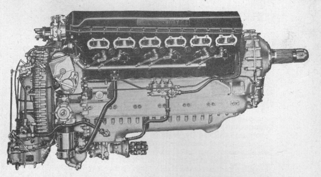
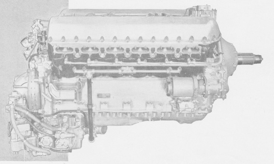
Basic component overview – Griffon 65
Cylinders Twelve cylinders consisting of high-carbon steel, floating wet liners set in two, two-piece cylinder blocks of cast aluminium alloy having separate heads and skirts. Cylinder liners chromium plated in the bores for 2 1⁄2 inches from the head. Cylinder blocks mounted with an included 60-degree angle onto inclined upper faces of a two-piece crankcase. Cylinder heads fitted with cast-iron inlet valve guides, phosphor bronze exhaust valve guides, and renewable “Silchrome” steel-alloy valve seats. Two diametrically opposed spark plugs protrude into each combustion chamber. Pistons Machined from “R.R.59” alloy forgings. Fully floating gudgeon pins of hardened nickel-chrome steel. Two compression and one drilled oil-control ring above the gudgeon pin, and another drilled oil-control ring below. Connecting rods H-section machined nickel-steel forgings, each pair consisting of a plain and a forked rod. The forked rod carries a nickel-steel bearing block which accommodates steel-backed lead-bronze-alloy bearing shells. The “small-end” of each rod houses a floating phosphor bronze bush. Crankshaft One-piece, machined from a nitrogen-hardened nickel-chrome molybdenum steel forging. Statically and dynamically balanced. Seven main bearings and six throws. Internal oilway, with feed from both ends, used to distribute lubricants to main and big end bearings. “Floating” front end bearing consisting of an internally toothed annulus bolted to crankshaft, meshing with and incorporating a semi-floating ring, internally splined to a short coupling shaft. Coupling shaft splined at front end to driving wheel of propeller reduction gear. Clockwise rotation when viewed from rear. Crankcase Two aluminium-alloy castings joined together on the horizontal centreline. The upper portion bears the wheelcase, cylinder blocks and part of the housing for the airscrew reduction gear; and carries the crankshaft main bearings (split mild-steel shells lined with lead–bronze alloy). The lower half forms an oil sump and carries the main pressure oil pump, supercharger change-speed operating pump and two scavenge pumps. It also houses the main coolant pump which is driven through the same gear-train as the oil pumps. Wheelcase Aluminium-alloy casting fitted to rear of crankcase. Carries the supercharger; and houses drives to the supercharger, auxiliary gearbox coupling, engine speed indicator, airscrew constant-speed unit, intercooler pump and fuel pump, as well as the oil and coolant pumps in the lower half crankcase. Valve gear Two inlet and two exhaust poppet valves of “K.E.965” austenitic nickel-chrome steel per cylinder. Exhaust valves have sodium-cooled stems. “Brightray” (nickel-chromium) protective coating to the whole of the combustion face and seat of the exhaust valves, and to the seat only of the inlet valves. Each valve is held closed by a pair of concentric coil springs. A single, seven-bearing camshaft, located centrally on the top of each cylinder head operates 24 individual steel rockers; 12 pivoting from a rocker shaft on the inner, intake side of the block to actuate the exhaust valves, the others pivoting from a shaft on the exhaust side of the block to actuate the inlet valves.
An innovation of more than usual interest was the adoption, on the Griffon 85, of a drive for contra-rotating airscrews; this engine appeared in the Spitfire XIV, 21 and Seafire 45. The Griffon 87 was a further development, rated at 2,145 h.p. maximum at 15,500 ft, and the 88 differed only in having an injection pump. “Contraprop” Griffons, of the 85, 87 and 88 series, were mounted in the Spitfire XIV and 21, and Seafire 45 and 47.
For the Barracuda V Rolls-Royce developed the Griffon 37, with a modified two-speed, single-stage blower, maintaining 18 lb/sq in boost in either gear. Though the Barracuda was provided with 2,055 h.p. at 2,250 ft, only Merlin powered machines of this type went into squadron service.
The most impressive of all Griffon developments was the three-stage supercharger incorporated in the 101 series, together with Rolls-Royce fuel injection. The new blower made possible an output of over 2,000 h.p. up to 20,000 ft with no increase in dimensions. Weight rose by 40 lb.
Notable among post-war developments is the Griffon 67, for use in long-range Service aircraft and having provision for contra-rotating airscrews. On this engine water/methanol injection is automatically brought into play when the boost pressure for the standard fuel approaches maximum value. The controlling unit works in conjunction with the boost control and progressively increases the flow of water methanol with boost pressures from 18.5 to 25 lb/sq in. Contraprop Griffons power the Avro Shackleton maritime-reconnaissance aircraft. Other variants of the Griffon are serving in the numerous marks of Fairey Firefly.
Unlike the Merlin, the Griffon was designed from the outset to use a single-stage supercharger driven by a two-speed, hydraulically operated gearbox; the production versions, the Griffon II, III, IV, and VI series, were designed to give their maximum power at low altitudes and were mainly used by the Fleet Air Arm. The Griffon 60, 70, and 80 series featured two-stage supercharging and achieved their maximum power at low to medium altitudes. The Griffon 101, 121, and 130 series engines, collectively designated Griffon 3 SML, used a two-stage, three-speed supercharger, adding a set of “Low Supercharger (L.S)” gears to the already existing Medium and Full Supercharger (M.S and F.S) gears. Another modification was to increase the diameters of both impellers, thus increasing the rated altitudes at which maximum power could be generated in each gear.[18] While the 101 continued to drive a five-blade propeller, the 121 and 130 series were designed to drive contra-rotating propellers. In 1946 a Griffon 101 was fitted to the Supermarine Spiteful XVI, RB518 (a re-engined production Mk.XIV); this aircraft achieved a maximum speed of 494 mph (795 km/h) with full military equipment.
The Griffon was the last in the line of V-12 aero engines to be produced by Rolls-Royce with production of the aero version ceasing in December 1955 after 8,108 were built, the Griffon 130 being the last in the series. Griffon engines remained in Royal Air Force service with the Battle of Britain Memorial Flight and power the last remaining airworthy Avro Shackleton.
A marine version, the Sea Griffon, continued to be produced for the RAF’s High Speed Launches.
Several North American Mustangs raced in the Unlimited Class races at the Reno Air Races have been fitted with Griffons. These include the RB51 Red Baron (NL7715C), “Precious Metal” (N6WJ) and a Mustang/Learjet hybrid “Miss Ashley II” (N57LR).[33] In all cases, Griffons with contra-rotating propellers, taken from Avro Shackleton patrol bombers were used in these aircraft. The RB51 Red Baron is noteworthy for holding the FAI piston-engine 3-kilometer world speed record from 1979 to 1989.
In 1965, SFR Yugoslavia used Griffon engines as the main power unit for their first domestically produced self-propelled artillery system, the S65, but the system was withdrawn from service in the early 1980s, because of poor fuel economy.
The 1980 Miss Budweiser Unlimited Hydroplane dominated the race circuit with a Rolls-Royce Griffon engine. It was the last of the competitive piston-engined boats, before turboshaft powerplants took over.
In modern day tractor pulling, Griffon engines are also in use, a single or double, rated each at 3,500 hp (2,600 kW).
Type: 12-cylinder supercharged liquid-cooled 60° Vee aircraft piston engine Bore: 6 in (152.5 mm) Stroke: 6.6 in (167.6 mm) Displacement: 2,240 cu.in (36.7 L) Length: 81 in (2,057 mm) Width: 30.3 in (770 mm) Height: 46 in (1,168 mm) Dry weight: 1,980 lb (900 kg) Valvetrain: Two intake and two exhaust valves per cylinder with sodium-cooled exhaust valve stems, actuated via an overhead camshaft. Supercharger: Two-speed, two-stage centrifugal type supercharger, boost pressure automatically linked to the throttle, water-air intercooler installed between the second stage and the engine. Fuel system: Triple-choke Bendix-Stromberg updraught, pressure-injection carburettor with automatic mixture control Fuel type: 100 Octane (150 Octane January to May 1945) Oil system: Dry sump with one pressure pump and two scavenge pumps Cooling system: 70% water and 30% ethylene glycol coolant mixture, pressurised. Liquid-cooled Intercooler radiator with its own separate system, again using 70/30% water/glycol mix. Reduction gear: 0.51:1, left-hand tractor Power output: 2,035 hp (1,520 kW) at 7,000 ft (2,135 m MS gear), +18 psi boost pressure at 2,750 rpm 2,220 hp (1,655 kW) at 11,000 ft (2,135 m MS gear), +21 psi at 2,750 r.p.m using 150 Octane fuel 1,820 hp (1,360 kW) at 21,000 ft (6,400 m) at 2,750 rpm Specific power: 0.91 hp/cu.in (41.4 kW/L) Compression ratio: 6:1 Power-to-weight ratio: 1.03 hp/lb (1.69 kW/kg)
Variants:
Griffon IIB 1,730 hp (1,290 kW) at 750 ft (230 m) 1,490 hp (1,110 kW) at 14,000 ft (4,270 m) Single-stage two-speed supercharger Impeller diameter 10 in (25.4 cm) Gear ratios 7.85:1, 10.68:1. Used on Firefly Mk.I and Spitfire XII.
Griffon VI Increased maximum boost pressure 1,850 hp (1,380 kW) at 2,000 ft (610 m) Impeller diameter 9.75 in (24.7 cm) Used on Seafire Mk.XV and Mk. XVII, Spitfire XII.
Griffon 57 and 57A 1,960 hp (1,460 kW) 2,345 hp (1,749 kW) with water-methanol injection on take-off Used on Avro Shackleton.
Griffon 58
Griffon 61 Introduced a two-speed two-stage supercharger with aftercooler similar to that on Merlin 61 2,035 hp (1,520 kW) at 7,000 ft (2,100 m) 1,820 hp (1,360 kW) at 21,000 ft (6,400 m) Used on Spitfire F.Mk.XIV, Mk.21.
Griffon 65 Similar to Griffon 61 with different propeller reduction gear Impeller diameters 1st stage: 13.4 in (34 cm), 2nd stage: 11.3 in (29 cm) Used on Spitfire F.Mk.XIV.
Griffon 72 Increased maximum boost pressure to take advantage of 150-grade fuel 2,245 hp (1,675 kW) at 9,250 ft (2,820 m)
Griffon 74 Fuel-injected version of Griffon 72; used on Firefly Mk.IV
Griffon 83 Modified to drive contra-rotating propellers 2,340 hp (1,745 kW) at 750 ft (230 m) 2,100 hp (1,565 kW) at 12,250 ft (3,740 m)
Griffon 85 2,375 hp (1,770 kW) Used on Spiteful Mk.XIV
Griffon 89 2,350 hp (1,755 kW) Used on Spiteful Mk.XV
Griffon 101 2,420 hp (1,805 kW) Two-stage, three-speed supercharger using Low Supercharger (L.S), Moderate Supercharger (M.S), or Full Supercharger (F.S) Reduction gear ratio 4.45 Rolls-Royce fuel injection system Used on Spiteful Mk.XVI
Griffon 130 2,420 hp (1,805 kW) at 5,000 ft (1,524 m) in L.S gear 2,250 hp (1,678 kW) at 14,500 ft (4,419 m) M.S 2,050 hp (1,529 kW) at 21,000 ft (6,400 m) F.S Reduction gear ratio 4.44 Modified to drive contra-rotating propellers Rolls-Royce fuel injection system