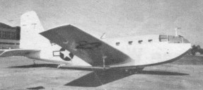
During 1942 the US Navy let contracts for the development of several amphibious transport gliders. Two of the contracts called for twelve-seaters manufactured primarily from non-strategic materials, these being the Allied XLRA 1 and the Bristol XLRQ 1.
The Allied XLRA 1 was a low wing cantilever monoplane constructed mainly of moulded plastic plywood and carrying two crew members seated in tandem, and ten troops. A jettisonable undercarriage was fitted this comprising a single twin wheel main member, a small tailwheel, and two small stabilising wheels attached at approximately quarter span, and it was intended that the glider would be towed by standard naval aircraft Two prototypes were built (BuAer Nos. 11647 and 11648), and one hundred production LRA Is (BuAer Nos. 31403 502) were ordered, but none of these had been completed when the U.S. Navy cancelled its glider programme. The LRA 2 was a proposed version with a conventional undercarriage.
Organized in January 1941 to make molded-plywood aircraft structures and in 1943 built large amphibious glider for US Navy. Was developing, in 1945, the prototype of the Allied Trimmer light twin-engined flying-boat amphibian. Manufacturing rights acquired by Commonwealth Aircraft Inc., Kansas City, Missouri.
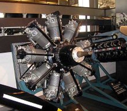
Alfa Romeo built/designed several aircraft engines based on Bristol Jupiter and Pegasus designs. These engines were named as 125, 126, 128, 129 and 131. The 126-RC34 was derived from Bristol Pegasus and 126-RC35 from Jupiter 9-cylinder radial design. All these engines were mainly fitted to Italian bombers in World War II. Between 1934 and 1944 Alfa Romeo built around 11,000 units.
Alfa Romeo Jupiter (Bristol) Power output: 313 kW (420 hp)
Applications: Caproni Ca.97
Alfa Romeo 125 RC.35 Power output: 485 kW (650 hp)
Established late 1909 at Berlin-Johannisthal by Dr Walter Huth as Pilot-Flugtechnische. The name was only briefly retained. At Albatros first built biplanes and (under license) French Antoinette monoplanes, but from 1911 was building highly efficient biplanes and in 1912 turned attention also to marine aircraft. In 1912 and later Hellmuth Hirth and others broke several records on Albatros landplanes. Development benefited from participation of Ernst Heinkel who, in 1913/14, designed a large single-engined three-bay biplane, forerunner of numerous reconnaissance and multipurpose types. The C III of 1915 remained in service until early 1917 and was built by several other firms. Historic line of single-seat fighters began with D.I and D.II, in service 1916. D.III (1917) was a “vee-strutter”; and W.4 a single-seat fighter seaplane, less known than landplanes though 118 were delivered to the German Naval Air Service. The decline of Albatros land fighters was marked by the company building the Fokker D.VII in 1918. The first civil aircraft was a single-engined six-passenger L.58 high-wing cantilever monoplane of 1923; L.73 was twin-engined transport; L.75 was biplane trainer and L.79 a single-seat biplane with symmetrical wing-section specially developed for inverted flight. L.100 was low-wing monoplane; L.101 a parasol monoplane. One Albatros biplane was adapted for advanced research (water tanks for trim, cameras etc.). Aircraft manufacture ceased 1930 and the company merged with Focke-Wulf 1930/31.
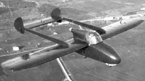
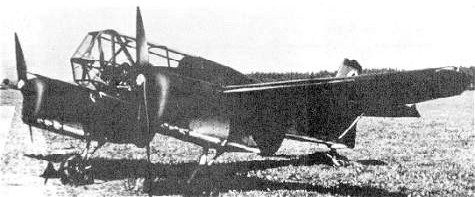
To practically test the position of the pilot, the Flugtechnische Fachgruppe (Aero-technical Group) Stuttgart constructed the FS17 research aircraft. The FS17 was a glider that was designed to withstand forces up to 14g. After the completion of the test program an order was given by the DVL ((Deutsche Versuchanstalt für Luftfahrt e.V. Berlin-Aldershof) (German Experimental Department for Aerospace Reg.) to the FFG Berlin ((Flugtechnische Fachgruppe)(Aero-technical Group)) to construct a powered aircraft. FFG Berlin was chosen as it possessed the necessary workshops and technicians. In the Spring of 1943 the FFG Berlin constructed the Berlin B9 to the specifications provided.
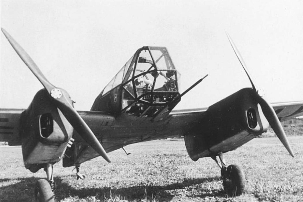
The Berlin B9 is a low winged type aircraft of standard layout. It is of mixed construction and stressed to accept 22g. The fuselage is constructed of steel tubing covered by timber ribbing and fabric covering. The fuselage is trapezoidal in cross-section. Its largest frame has an area of 0.67sq.m. The fuselage diminishes in area towards the rear and finishes in the empennage. The cockpit is covered with a 1.5m long, clear canopy that is jettisonable. The fuselage bolts to the wings at four points.
The single leg retractable undercarriage is borrowed from the Me108. It is raised and lowered by a hand ratchet. The empennage consists of a fin with balanced rudder and elevators that is attached to the end of the fuselage. The elevators have a range of 30 per cent (27 degrees).
The wing assembly consists of a rectangular centre section and two trapezoid like outer sections. The leading edge is square to the fuselage for half of its length. At the point where the outer panel is connected, a trail of 2 degrees is introduced. This is held for the remaining length of the wing.
The wing is constructed of two box like spars. These are situated at 20 per cent and 50 per cent through the wing from the leading edge. Dural sheets are glued to the spars for the purpose of providing attachment points for the wing to the fuselage and the engine to the wing. Solid planking to withstand the torsional forces generated by high acceleration manoeuvrers covers the area between the spars. The mounting struts for the motors are situated within the engine nacelles. The four fuel tanks are placed between the spars on either side of the motors. The rudder and flaps mechanisms are situated just behind the last wing spar. The flaps are situated below the fuselage. They are 20 per cent of the width of the wing and can be extended to 60 degrees.
Two Hirth Type HM500 motors generating 105 PS drive two fixed pitch Schäfer propellers.
The aircraft was designed to accommodate a pilot lying in the prone position. As such it needed a flight control system that did not load up under high acceleration and needed no extra pilot training to be able to use. A fundamental change to the flight controls was out of the question. The decision was made to employ a control column instead of a control wheel.
Cockpit layout is far more important in an aircraft designed for prone operation that in an aircraft where the conventional sitting position is employed. The cockpit must be layed out in a definite right and left side pattern. Crossing hands to manipulate controls in the prone position creates significant difficulties for pilots. Blohm & Voss encountered this problem with control columns in some of their work. They also discovered that by using a small control column, the left hand could also be used to control the aircraft if the right hand was incapacitated. In the Berlin B 9, the right hand is used to control the elevators and ailerons. It is also given the task of releasing the pilots harness and the canopy release. The left hand operates all the other controls and instruments. The feet, in the same fashion as in a conventional sitting position, operate the rudder and brakes.
In the FS17 and the first mockups of the Berlin B 9, the control column was situated centrally. In the finished Berlin B 9, the control column was located asymmetrically and approved for right-handed flight only. Even so, the left hand can be used to control the aircraft if necessary. This design change severely restricts the downward field of view to the point where ground observation is not one of the strong points of this aircraft.
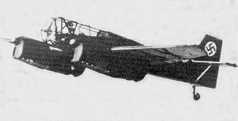
The Berlin B 9 was completed in the Spring of 1943, and under the supervision of H.W. Lerche of the experimental station at Rechlin, the aeroplane made it’s first test flight.
As of August 1943, the Berlin B 9 was presented to official Departments involved. By November 1943 thirty pilots had flown and evaluated the aeroplane. Only one accident occurred during the entire program. This occurred when a pilot made an error that may have ended up in an aborted take-off. The damage was repaired within three weeks.
The prone position of the pilot was generally indicated as being comfortable. On occasion there was a request for softer upholstery. Fatigue and tiredness was experienced in the neck (from head lifting) and shoulder muscles from moving the upper arms and the incorrect positioning of the parachute harness. Flying in a combination of winter equipment and heavy furs was noted as being tiring.
Pilots who flew the aircraft often soon adjusted to the prone position and were able to make 1 ½ hour flights without discomfort.
A chin support was considered bothersome in horizontal flight. The cockpit configuration without the chin support and the parachute on the pilot’s back was favoured most pilots. Although under high g loads a chin support was seen as being imperative. The control column was changed to become vertical and was accepted as being more comfortable by the pilots. The forces need to control the aircraft were considered as being too low. Most pilots were used to controlling much heavier aircraft. As a result, the gearing of the rudder control was changed to increase the load needed to move the rudder in flight. Several pilots took some time to get used to the feel of the rudder. No problem was encountered with the amount of force needed to operate the elevators. Cramps that developed in flight caused some difficulty to the pilots. By performing rolling exercises on the ground, leg muscles soon became accustomed to the position and cramps ceased to develop. Pilot’s legs were very sensitive to the wrong length settings for the pedals.
The Berlin B 9 was able to achieve accelerations of 8.5g when pulling out of dives and 6g over several seconds in steep spiral climbs. Accelerations of these magnitudes are not endurable by pilots when in the normal seated position. At the beginning of the test program, these forces were only recognised by the heaviness of the head and limbs. These forces did not impair the pilot’s mental and physical reactions. Because of this, pilots often underestimated the number of gs they had pulled.
The Berlin B 9’s speed and ability to generate higher forces was restricted by the fixed pitch and relatively low rotational speed, Schwarz propellers.
The Berlin B 9, had shown how prone cockpits not only resisted g better but also reduced frontal area.
Pilots who flew in the Berlin B 9:
Eingeflogen durch Haupt-Ing. H.W. Lerche, Rechlin – 10. 4. 43
Ing. L. Schmidt, FFG Berlin (Flugerprobung) – 14. 4. 43
Dipl.-lng. E. G. Friedrichs, FFG Berlin und DVL (Flugerprobung) – 14. 4. 43
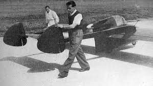
The Airspeed AS.54 was a two-seat training glider designed to A.M. Spec. TX3/43, to train pilots to fly large transport gliders. Wood and ply construction, it was not built.
The undercarriage was self-jettisoning mainwheel and central skid. Dive brakes and split trailing-edge flaps were designed and water ballast was in the fuselage.
The wing was three-piece, with a centre-section of 4.57 m / 15 ft span, stut braced.
Wingspan: 10.97 m / 36 ft 0 in Wing area: 14.59 sq.m / 157 sq.ft Length: 8.18 m / 26 ft 10 in AUW: 853 kg / 1880 lb Wing loading: 58.6 kg/s.m / 12 lb/sq.ft Max speed: 322 kph / 200 mph Stall: 79 kph / 49 mph
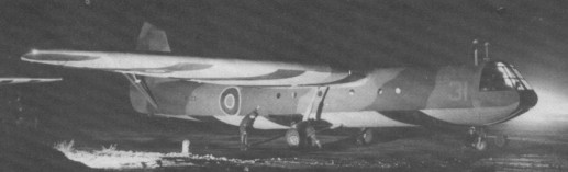
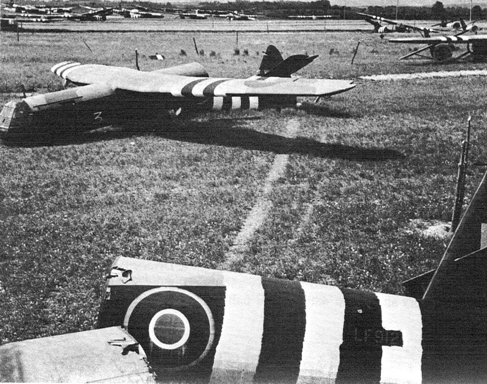
A high-wing military transport glider with accommodation for 25 troops or freight, including vehicles, of wooden construction. Designed by A.H. Tiltman to Air Ministry Spec. X26/40 The AS.51 Horsa I featured tricycle undercarriage with jettisonable main wheels, main central skid. The cantilever wing was in three pieces. Airbrakes were on the lower surfaces of the wings and pneumatically-operated split flaps were fitted.
The prototype first flew on 12 September 1941 at Great West Aerodrome and the production AS.51 Horsa I entered service in late 1942.
The AS.58 Horsa II differed from the Mk I by having a hinged nose section to allow ease of loading. The prototype Horsa II first flew in 1943.
The first operational mission with Horsas was the invasion of Sicily in 1943, but they were also used during the D-day landings, when Horsa gliders were towed by Whitley and C-47 aircraft.
6 June 1944 Orne Estuary, Normandy
The US forces also received several hundred of these gliders.