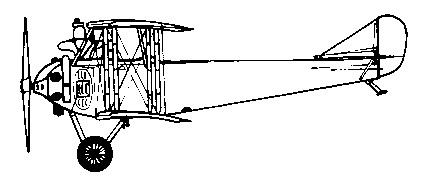
Engine: Salmson 9 U, 148 hp Length: 26.575 ft / 8.1 m Wingspan: 37.467 ft / 11.42 m Wing area: 398.268 sqft / 37.0 sqm Max take off weight: 2566.6 lb / 1164.0 kg Wing load: 6.36 lb/sq.ft / 31.00 kg/sq.m Max. speed: 78 kts / 144 km/h Service ceiling: 14108 ft / 4300 m Endurance: 4 h Crew: 2 Armament: 2x MG
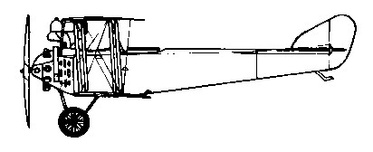
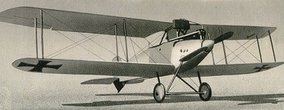
The Anatra D reconnaissance aircraft of 1915 was a German Albatros derivative, with a rotary engine.
Engine: Gnome Monosoupape, 99 hp Length: 25.262 ft / 7.7 m Wingspan: 37.73 ft / 11.5 m Wing area: 376.74 sqft / 35.0 sqm Max take off weight: 1907.3 lb / 865.0 kg Max. speed: 71 kts / 132 km/h Service ceiling: 13123 ft / 4000 m Wing load: 5.13 lb/sq.ft / 25.00 kg/sq.m Endurance: 4 h Armament: 1x MG
Zavod A.A. (for Arturo Antonovich) Anatra was founded at Odessa in 1913. Important during First World War, with factories at Odessa and Simferopol, Ukraine, by 1917 the company was building their own designs, plus Voisins and Nieuports, to a total monthly output of 80. The Companys activities ceased in the early 1920s.
Félix Amiot started his firm Amiot – S.E.C.M in 1916, building Bréguet and Morane-Saulnier machines under licence.
Avions Amiot products were known formerly by SECM prefix, latterly as SECM-Amiot or generally, Amiot, after founder Felix Amiot. In 1929 Amoit amalgamated with Avions Latham. The firm concentrated on large all-metal multi-engined aircraft, using light-metal stampings, though well before 1940 introduced stressed-skin construction. In the 1930s works at Colombes and Caudebec were reconditioning several types of metal aircraft for French Government. Changes in structural techniques were matched by aerodynamic advances; thus, the Amiot 143.
In May 1917, one month after the US had declared war on Germany, a Federal task force known as the Aircraft Production Board summoned top engine designers Jesse G. Vincent (of the Packard Motor Car Company of Detroit) and E.J. Hall (of the Hall-Scott Motor Co. of Berkeley, California,) to Washington D.C. They were given the task of designing as rapidly as possible an aircraft engine that would rival if not surpass those of Great Britain, France, and Germany. The Board specified that the engine would have a high power-to-weight ratio and be adaptable to mass production. The Board brought Vincent and Hall together on 29 May 1917 at the Willard Hotel in Washington, where the two were asked to stay until they produced a set of basic drawings. After just five days, Vincent and Hall left the Willard with a completed design for the new engine.
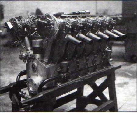
The Liberty L-12 was a modular design where four or six cylinders could be used in one or two banks. A single overhead camshaft for each cylinder bank operated two valves per cylinder, in an almost identical manner to the inline six-cylinder German Mercedes D.III and BMW III engines, and with each camshaft driven by a vertical driveshaft that was placed at the back of each cylinder bank, again identical to the Mercedes and BMW straight-six powerplants. Dry weight was 844 lb (383 kg). Fifty-two examples of a six-cylinder version, the Liberty L-6, which very closely resembled the Mercedes and BMW powerplants in overall appearance, were produced but not procured by the Army. A pair of the 52 engines produced were destroyed by Dr. William Christmas testing his so-called “Christmas Bullet” fighter.
In July 1917, an eight-cylinder prototype assembled by Packard’s Detroit plant arrived in Washington for testing, and in August, the 27-litre (1,649 cubic inch) water-cooled 45° V-12 12-cylinder version was tested and approved. That fall, the War Department placed an order for 22,500 Liberty engines, dividing the contract between the automobile and engine manufacturers Buick, Ford, Cadillac, Lincoln, Marmon, and Packard. Hall-Scott in California was considered too small to receive a production order. Manufacturing by multiple different factories was facilitated by its modular design. Cadillac was asked to produce Liberty engines but William Durant was a pacifist who did not want General Motors facilities to be used for producing war material. This led to Henry Leland leaving Cadillac to form the Lincoln company to make Liberty engines. He quickly gained a $10,000,000 government contract to build 6,000 engines. Subsequently the order was increased to 9000 units, with the option to produce 8000 more if the government needed them.
However, Durant later changed his mind and both Cadillac and Buick produced the engines.
Other manufacturers in the program included Packard, Ford and Marmon. Lincoln had delivered 6500 of the 400 hp, V-12, overhead camshaft engines when production ceased in 1919.
Ford was asked to supply cylinders for the new engine, and rapidly developed an improved technique for cutting and pressing steel which resulted in cylinder production rising from 151 per day to over 2,000, Ford eventually manufacturing all 433,826 cylinders produced, and 3,950 complete engines. Lincoln constructed a new plant in record time, devoted entirely to Liberty engine production, and assembled 2,000 engines in 12 months. By the time of the Armistice with Germany, the various companies had produced 13,574 Liberty engines, attaining a production rate of 150 engines per day. Production continued after the war, for a total of 20,478 engines built between July 4, 1917 and January 1919.
While the 12-cylinder prototype was completed only 28 days after the first drawings were made, more than 1000 modifications to the design had to be made between September 1917 and February 1918. Nevertheless, 1050 Liberties were delivered to Britain between March and July 1918. They were fitted in the DH.9A.
Although it is widely reported otherwise, a few Liberty engines did see action in France as power for the American version of the DeHaviland DH4.
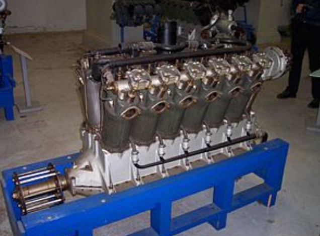
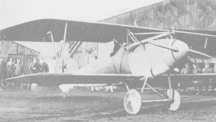
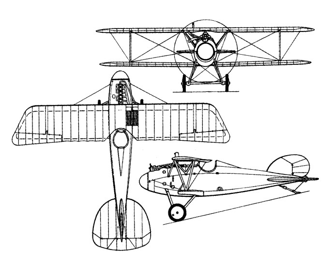
The Polikarpov I-2 used the M-5 engine with 12 cylinders in V and 420 hp of power (copy under license of the North American Liberty L-12 engine). It stood out for the careful work on the engine hood, of which at least two types were used. The most remarkable symbol of the upper region of the hood was the pipe through which the air flow entered the two “Zenit” carburettors. Cooling was basically achieved by means of a Lamblin radiator that could vary its angle of incidence by around 70º. The control of this radiator was carried out from the cockpit. A number of I-2s were delivered with fixed radiators attached to the fuselage.
Mikulin M-5
The Mikulin M-5 engine was used in the Grigorovich I-1, I-2 and MRL-1 fighters.
Variants:
V-1650 An inverted Liberty 12-A was referred to as the V-1650 and was produced up to 1926 by Packard — exactly the same designation was later applied, due to identical displacement, to the World War II Packard-built version of the Rolls-Royce Merlin.
Nuffield Liberty The Nuffield Liberty tank engine was produced in World War II by the UK car manufacturer Nuffield. It was a 27 L (1,649 in3) engine with an output of 340 hp (250 kW), which became inadequate for the increasing vehicle weights as the war progressed, and it suffered numerous problems with cooling and reliability. It was replaced in later British tanks by the Rolls-Royce Meteor, based on their Merlin aero engine.
Allison VG-1410 The Allison VG-1410 was an air-cooled inverted Liberty L-12, with a geared super-charger and Allison epicyclic propeller reduction gear and reduced displacement. (45⁄8″x7″=1,411 cu.in.)
Liberty L-6 A 6-cylinder version of the Liberty L-12, and nicknamed the “Liberty Six”:- a single bank of cylinders, with the resulting engine bearing a strong external resemblance to both the Mercedes D.III and BMW III straight-six German aviation engines of World War I.
Liberty L-8 An 8-cylinder V engine using Liberty cylinders in banks of four at 90°.
Applications:
Airco DH.4 Airco DH.9 Caproni Ca.60 Curtiss NC Curtiss Carrier Pigeon Airco DH.10 Douglas C-1 Douglas DT Douglas O-2 Fokker T.II Handley Page H.P.20 Witteman-Lewis XNBL RN-1 (Zodiac) Babs (land speed record car)
Specifications:
Liberty L-12 Type: 12-cylinder liquid-cooled Vee piston aircraft engine Bore: 5 in (127 mm) Stroke: 7 in (178 mm) Displacement: 1,649.3 cu in (27.03 l) in3 (27 L) Length: 67.375 in (1,711 mm) Width: 27 in (685.80 mm) Height: 41.5 in (1,054.10 mm) Dry weight: 845 lb (383.3 kg) Valvetrain: One intake and one exhaust valves per cylinder operated via a single overhead camshaft per cylinder bank Fuel system: Two duplex Zenith carburettors Fuel type: Gasoline Oil system: forced feed, rotary gear pressure and scavenge pumps, wet sump. Cooling system: Water-cooled Power output: 449 hp (334.8 kW) at 2,000 rpm (takeoff) Specific power: 0.27 hp/cu in (12.4 kW/L) Compression ratio: 5.4:1 (Army engines) 5:1 (navy engines) Specific fuel consumption: 0.565 pt/hp/hour (0.43 l/kW/hour) Oil consumption: 0.0199 pt/hp/hour (0.0152 l/kW/hour) Power-to-weight ratio: 0.53 hp/lb (0.87 kW/kg)
Hall-Scott L-6 / Liberty 6 1919 6-cylinder 224hp@1700rpm to 244hp@1830rpm 825.67ci dry wt: 546 lb
The Albatros J.I was conceived of as a dedicated ground attack aircraft for use in the “infantry close-support role” during World War 1. Taking the wing assemblies and empennage of the C.XII, Albatros built a new fuselage. Unique to the J.I was the addition of armour steel plate to help protect the crew during their low-level attack runs over hostile territory. This armour added much weight some 1,080lbs. To achieve the low-level strafing role required, the J.I was fitted with a pair of downward-firing machine guns controlled by the pilot. First flight of the J.I was recorded in 1917 and the aircraft went into operational status that same year.
Despite its drawbacks, the J.I did achieve a certain level of success as a dedicated ground-attack platform and about 240 production examples were built by war’s end.
A biplane design, the Albatros J.I featured a downward-sloping forward fuselage., keeping the engine at a low level when compared to most other biplane designs. The engine was fitted in a forward-set compartment ahead of the cockpit and protruded from the top of the fuselage. The engine powered a two-bladed propeller made of wood. The pilot saw just aft of the engine and under the upper wing assembly. To his rear was the observer/rear cockpit gunner. Wings were equal span with parallel struts and dual bays, additionally braced at the fuselage. The rounded fuselage tampered off to a point at the rear to which was affixed a rounded, swept-back vertical tail fin and a pair of horizontal planes set well-aft. A ventral “fin” type structure was noted under the fuselage rear and this helped to support the tail skid. The main undercarriage was fixed and each single-wheeled landing gear leg was supported by two struts emanating from the fuselage with a connecting strut joining the two legs together.
As an infantry close-support platform, the J.I armament was 2 x 7.92 Spandau LMG 08/15 series aircraft machine guns arranged in a fixed, downward angle, suitable for making strafing runs against trench formations. The rear 1 x 7.92mm Parabellum MG14 series machine gun served as a self-defence measure. This machine gun was fitted to a trainable mount.
Beyond the Luftstreitkrafte of the German Empire, the only other noted operator of the J.I became Poland but these were fielded in the years following the close of World War 1. Some 10 such aircraft in Polish service served up until 1921 before being retired.
The less successful J.II, powered by a 164kW Benz Bz.IVa, had extra armour plating to protect the engine and so lost the pointed nose and propeller spinner.
Albatros J.I Engine: 1 x Benz Bz.IV inline, 150- or 200 hp Length: 28 ft 10 in (8.8m) Wingspan: 46 ft 4 in (14.14m) Height: 11 ft 10 in (3.37m) Wing area: 42.8 sq.m / 460.69 sq ft Empty Weight: 3,082lbs (1,398kg) Maximum Take-Off Weight: 3,986lbs (1,808kg) Maximum Speed: 87mph (140kmh; 76kts) Cruise speed: 110 km/h / 68 mph Range w/max.fuel: 350 km / 217 miles Range w/max.payload: 275 km / 171 miles Rate-of-Climb: 400ft/min (122m/min) Service Ceiling: 14,764ft (4,500m) Endurance: 2 hours and 30 minutes Crew: 2 Armament: 2 x 7.92mm Spandau LMG 08/15 machine guns, 1 x 7.92mm Parabellum MG14 machine gun
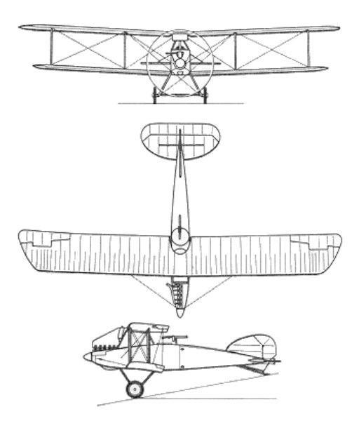
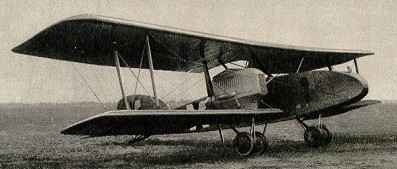
The G.II prototype first flew in mid-1916 and G.III entered service in Macedonia and elsewhere in the following year. Armament comprised two Parabellum machine-guns – one each in nose and rear cockpits – plus 320kg of bombs. A medium bomber powered on the G.III limited production version by two 164kW Benz Bz.IVa pusher engines mounted on the lower wings. The trailing-edges of the inner sections of the lower wings were cut away to allow the engines and propellers to be fitted further forward on the wings than would otherwise be possible.
Engine: 2 x Benz Bz IVa, 147kW Wingspan: 18.0 m / 59 ft 1 in Length: 11.9 m / 39 ft 1 in Height: 4.2 m / 13 ft 9 in Wing area: 79.0 sq.m / 850.35 sq ft Take-off weight: 3150 kg / 6945 lb Empty weight: 2064 kg / 4550 lb Max. speed: 150 km/h / 93 mph Range w/max.fuel: 600 km / 373 miles Crew: 3
The W.4 was a sea-plane development of the D.I and 117 were built for the German Navy to defend coastal naval bases from attack. Most were stationed at North Sea bases from early 1917, but a small number were deployed around the Aegean Sea area. The W.4 was a two seater powered by the 160 hp Mercedes D.III, and normally armed with one or two Parabellum 7.92 mm machine guns in the rear cockpit.
Engine: 1 x Mercedes D III, 125kW Wingspan: 9.5 m / 31 ft 2 in Length: 8.5 m / 27 ft 11 in Height: 3.7 m / 12 ft 2 in Wing area: 31.6 sq.m / 340.14 sq ft Take-off weight: 1070 kg / 2359 lb Empty weight: 790 kg / 1742 lb Max. speed: 160 km/h / 99 mph Ceiling: 3000 m / 9850 ft Range w/max.fuel: 450 km / 280 miles Armament: 2 machine-guns Crew: 1
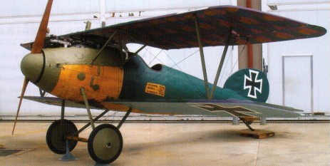
Early in 1917 Albatros began with a drag-reduced development of the D III fighter, featuring a deeper oval-section fuselage, a head rest (often removed as it interfered with the pilot’s rearward view), and reduction of the gap between the top of the fuselage and the upper wing by about 4 inch. Also included were a revised of the rudder, different aileron-control system, and a larger spinner. The under-fin vertical trailing edge was raked back at 45 degrees on the D.V. The under-fin vertical trailing edge was raked back at 45 degrees on the D.V.
The D.III’s wing and tailplane to the new fuselage and fin just transferred the structural problems to the new type. These were not corrected until the strengthened D.Va model.
The new D V entered service in May 1917 and was soon joined by the slightly different D Va. More than 1,000 examples of the two similar variants were in service during May 1918 over the Western, Italian and Palestinian fronts. No fewer than 1512 D.V and Va models served on the Western Front, plus many others in Macedonia, Pales¬tine and northern Italy.
Despite its aerodynamic re¬finement over the D III, the DV was no real match for the best of Allied fighters. Losses to Allied fighters were heavy, and the type also suffered a heavy accident rate as the lower wing had an alarming tendency to break away in highly stressed maneuvers.
Principal versions were the D V (basic version) and D Va (derivative with the upper wing and aileron control system of the D III).
Principal users were Austria-Hungary, Germany, and Turkey.
Albatros D.V Engine: 1 x Mercedes IIIa engine, 180-200-hp (134-149-kW). Length: 24 ft 0.5 in (7.5m) Wingspan: 29 ft 8.25 in (9.05m) Height: 8 ft 10.25 in (2.67m) Wing area: 228.2 sq ft (21.20 sq.m) Empty weight: 1,515 lb (687 kg) Maximum Take-Off Weight: 2,059lbs (934kg) Maximum Speed: 116mph (186kmh; 100kts) at 3280 ft/1000 m Climb to 3,280 ft (1,000 m): 4 min Service Ceiling: 18,698ft (5,699m) Endurance: 2 hr. Armament: two 7.92-mm (0.312-in) Spandau machine guns. Accommodation: 1
D.Va Engine: 1 x Mercedes Illa 6-cylinder in-line, 180hp Length: 24.61ft (7.5m) Wingspan: 29.69ft (9.05m) Height: 8.86ft (2.70m) Empty Weight: 1,510lbs (685kg) Maximum Take-Off Weight: 2,059lbs (934kg) Maximum Speed: 116mph (186kmh; 100kts) Maximum Range: 232miles (373km) Rate-of-Climb: 908ft/min (277m/min) Service Ceiling: 18,698ft (5,699m) Armament: 2 x 7.92mm machine guns Accommodation: 1