Caquot Balloon

Caquot Type R

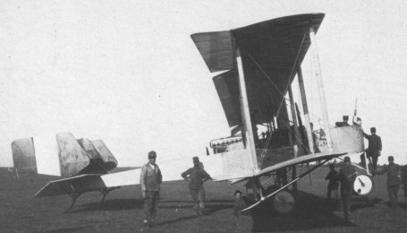
At the start of World War I observation balloons, the use of which was discontinued in France in 1912, were needed on the battlefield, and the Germans used them in large quantities called Drachen. The French who did not have any in their boxes therefore began to copy these German balloons.

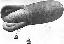
While he was mobilized on 1st August 1914 to command the 21th company of balloonists, Albert Caquot performed some aerial observations in a spherical ball type from 1880, then found that the information given by the observers are not reliable due to the instability of the aerostats which makes them sick even in light winds. He then designed a new balloon stabilized by three inflatable rear lobes arranged at 120°. He then sent his plans and calculations to the Atelier de Chalais-Meudon in October 1914 and was received by the director of the establishment in November; but he is not convinced by his idea. Despite everything, he decides to entrust the realization of Caquot’s plans to a team of designers from his design office, they are carried out in a week. In the meantime General Hirschauer, who is in charge of aviation at the Ministry of War, orders that a test be carried out. Caquot then obtained authorization to build a prototype, which was done in February 1915.

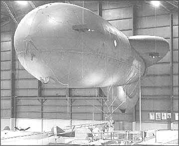
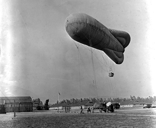
The Caquot type L balloon is then compared to a spherical balloon and a copy of Drachen. It immediately proves to be more efficient, its hull offering minimum resistance to the wind. It managed to withstand winds of 90 km / h against only 54 km / h and 36 km / h for the Drachen and the spherical balloon. Its performance is due to the ovoid shape of the balloon which allows less aerodynamic resistance, and above all to its three inflatable tail units at the rear but based on an internal structure fixing them rigidly to the hull at an angle of 120°. This makes it possible to avoid the pendulum movement of the balloon during gusts of wind, which made observers sick.

Despite these conclusive tests, series production is not launched. However, an English naval officer, who attended the prototype tests, told Caquot that the British navy was trying to equip its fleet with captive balloons, but that they could not withstand bad weather. He then asks her to help them. By examining the constraints, Caquot realizes that the aerostats must resist winds of 125 km / h since in addition to the wind is added the speed of the ship. He then designed a specific braked winch that allowed the balloon to be carried away by too strong gusts and then return once the gust was over.

A French Caquot type observation balloon in 1915.

This ability proved itself in an account of a “free balloon” flight taken by Capt. F. H. Cleaver, commanding officer of the RFC’s No. 1 Kite Balloon Section on October 27, 1915:

The speed and direction of the wind was tested and found to be 15 m.p.h. by the air meter. The balloon was then let up and marched for 300 yards to the winch; it was easily controlled by the balloon party. The winch was shackled on and I and Lieut. Beaufort ascended; the wind appeared to be increasing, the speed was again taken from the balloon and found to be 30 m.p.h. The guy of the right sail carried away, which caused the balloon to oscillate considerably, thus increasing the strain on the cable and rigging. On this an order was immediately given to haul down. The winch, whose power is only 6 horse failed; the wind was rapidly increasing in strength and on again being tested the speed was found to be 40 m.p.h. Fortunately for the occupants of the balloon the cable then parted, had it not done so the rigging most certainly would have gone. The valve rope was immediately pulled and as soon as the end of the cable or any part of it touched the ground, the balloon in spite of the loss of gas naturally was lightened owing to being relieved of the weight of a portion of the cable, and ceased to descend and at times rose; this coupled with the heat of the sun causing the gas to expand and the balloon to become still lighter, was responsible for what might appear to be a long flight, which owing to the speed of the wind was carried out at 40 m.p.h. A perfect landing was effected in 45 minutes without any damage to the balloon, occupants and instruments.

These qualities quickly proved the Caquot to be the best balloon design on the Western Front and all the combatant nations eventually adopted it.

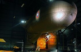
In June 1915, Albert Caquot became director of the mechanical aerostation workshop at Chalais-Meudon, where he had new aerostats built in large series according to his plans. On July 10, 1916, the British Aviation Inspector requested M type balloons from the War Department. Between July and the end of November 1916, 46 M type balloons were built in Chalais-Meudon for the British, subsequently ‘others are built in the UK. Three types of balloons with a capacity of 750 cu.m, 820 cu.m and 1000 cu.m. The first equip small ships used for the research of submarines, they are served by two men from an altitude of 500 m; the larger ones are used aboard squadron ships for the adjustment of fire and are served by a crew of three observers at 500 m altitude or two at 1000 m. This use of Caquot balloons allows the British Navy to reduce its losses. In 1917, the French navy, noting that its losses due to torpedoing were becoming higher than those of the British, then decided to adopt the Caquot balloons as well. The French Navy uses types P and P2 on its smaller units for protection against U-boat attacks, and the Type R to direct the fire of its larger ships. In July 1918, it had nearly 200 balloons and 24 units designed to work with them.

The French Army, for its part, trained 76 units during the war equipped with Caquot balloons. These balloons are used for artillery tuning and general observation of the battlefield.

In 1917, when the Germans began to bombard Paris with aircraft, Albert Caquot proposed to make barrages with low volume balloons, the cables of which would force the bombers to climb higher and reduce their load. This idea is taken up by the British in September 1917. At the end of the war, there are Caquot type of balloons, mainly with M 900 cu.m and R 1000 cu.m.

The Caquot balloon entered service in other Allied armies and then in others including the new Polish army.

In France, the production of balloons was 319 units per month in 1919. The first models are of type L and M, and finally the Caquot balloons are produced in four different formats:

P – 750 m³ (capacity – two observers at the height of 500 m)
P2 – 820 m³
M2 – 930 m³
R – 1000 m³ (capacity – two observers at the height of 1000 m or three at 500 m)

During the war, one of the British Caquot balloons fell into the hands of the Germans who made a copy called Ae 800 for Achthundert english 800 which was a reference to the cubic meter capacity.

Type Ae

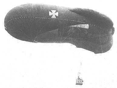
General Ernst von Hoeppner, commander of the German Luftstreitkräfte freely admitted that German balloons put in service after 1916 were patterned after a captured British example. Caquots and their German copies eventually served on all fronts and with naval forces operating in the Atlantic and Mediterranean. The improved Caquot could ride higher, and fly in higher winds than the Parseval-Sigsfeld, so it quickly replaced the Drachen, even among the Luftschiffertruppen.

During the war, France was from 1915 the leading power in the field of ballooning and built nearly 4,200 captive balloons: 1,700 observation balloons and 2,500 barrage balloons.

The Caquot balloon was manufactured in large numbers, including a thousand in the United States between 1918 and 1919.

Caquot Type R at the National Museum of the United States Air Force

The United Kingdom built others during World War II where they were used until the 1960s to test parachutes, for non-combat aerial observation and photography.

A type R Caquot on the Arcadia Balloon School of the United States Army Air Service in the city of Arcadia (California) in 1921.

Gallery

P
Capacity: 50 m³
Payload: two observers
Altitude: 500 m

P2
Capacity: 820 m³

M2
Capacity: 930 m³

R
Capacity: 1000 m³ / 32,200 cu.ft
Payload: two observers to 1000 m / three observers to 500 m
Length: 92 ft
Diameter: 32 ft
Cruising speed: 75 km / h
Max wind speed: 70 mph

Caquot, Albert

Albert Caquot, in a dark jacket in the foreground (the 2 nd from the right), in the premises of the École Polytechnique

Albert Irénée Caquot, born on 1st July 1881 in Vouziers (Ardennes) and died on November 28, 1976 in Paris at 95, was considered “the greatest of living French engineers” for half a century.

Albert Caquot Article

Large landowners, his parents, Paul Auguste Ondrine Caquot and Marie Irma Cousinard 2 , wife Caquot, “run a large family farm, adjoining a mill on the banks of the Aisne”, in Vouziers in the Ardennes. His father opened this farm to modernism, installing electricity and telephones in his home in 1890.

Just one year after leaving the high school Reims, eighteen years, Albert Caquot received 29 e the entrance exam to the Ecole Polytechnique (class of 1899) which he graduated ranked 15th, and enters the body of bridges and roads.

From 1905 to 1912, he was a bridge and road engineer in Aube, in Troyes, and stood out for the important sanitation measures he developed. These saved many human lives and protected the city from the great flooding of the Seine in 1910.

In 1912, he joined the reinforced concrete design office of Armand Consideration as a partner, where he gave free rein to his talent as a designer of civil engineering structures. In 1914, after the death of Armand Considere, the office became “Pelnard-Considerere & Caquot”. It was in this same context that he worked from 1919 to 1928, from 1934 to 1938, then from 1940.

During his life, Albert Caquot taught for a long time the resistance of materials at the Ecole Nationale Superieure des Mines in Paris, the Ecole Nationale des Bridges et Chaussées and the Ecole Nationale Supérieure de l’Aéronautique.

During his career he produced more than three hundred civil engineering works of all kinds, several of which were then world records.

Two achievements contribute to its international reputation:

The internal reinforced concrete structure of the large statue of Christ the Redeemer on Mount Corcovado (1931, height 30 m and weight 1,145 t), in Rio de Janeiro, the work of French sculptor Paul Landowski and, for the head of Christ, by Romanian sculptor Gheorghe Leonida.

The George V Bridge in Glasgow (Scotland) on the Clyde for which Scottish engineers are asking for help.

The Christ of Corcovado whose internal structure is due to Caquot.

He devoted his life to aeronautics and civil engineering in alternating periods at the pace imposed by the First and Second World Wars. Albert Caquot’s contributions to aeronautics are invaluable, from the development of the propeller engine and the opening up of the Air Ministry to technical innovations, to the founding of the first institutes of fluid mechanics. Marcel Dassault, who was commissioned by Albert Caquot to build a prototype of the postal three-engine program, wrote of him: “He is one of the best technicians that aviation has ever known. He was a visionary who, in all areas, looked to the future. He was ahead of everyone.”

From 1901 he carried out his military service in a battalion of balloonists. At the start of the Great War, he found a battalion of balloonists from Toul as captain. For a wind speed greater than 22 km/h, it highlights the great instability of the spherical balloon with which the units are equipped. In 1915, he produced a tapered tethered balloon model equipped with rear stabilizers on the Drachen principle developed by the German August von Parseval, allowing observation by winds of 90 km/h. The Chalais-Meudon aerostatic workshop then began to manufacture “Caquot balloons” for all the Allied armies. The winch with constant braking torque that it creates allows it to adapt its balloons to the Allied fleets (fire control and detection of submarines) and to make them withstand winds of up to 125 km/h. Also called a “sausage”, this captive balloon gives France and its Allies a major strategic advantage. In January 1918, Clemenceau appointed him technical director of military aviation.

A French Caquot type observation balloon in 1915.

In 1919, Albert Caquot was behind the creation of the French Air Museum, today the Air and Space Museum at Le Bourget. It is the oldest aeronautical museum in the world.

In 1935, he built a double canopy hangar 120 m long, 60 m wide by 9 m free height and its annexes for around 10,000 m2 at Fréjus on the naval air base.

In 1928, he became the technical director general of the newly created Air Ministry. It practices a policy of research, prototypes and mass production which gives France back the industry it deserves.

In 1934 he preferred to retire and devote himself again to civil engineering. In 1938, under the threat of war, Albert Caquot was recalled to assume the joint presidency of all the national aeronautical companies. In July 1939, he also took over the role of technical director general of the Air Ministry but, although he had spectacularly turned around the production of aircraft, the obstacles he encountered on the part of the staff and the management of the control led him to submit his resignation in 1940.

Numerous honorary distinctions from all countries that have been awarded to him, including the dignity of Grand Cross of the Legion of Honour in 1951.

He chaired many French scientific organizations for more than twenty years, such as the National Council of French Engineers and the Société d’Enouragement pour l’Industrie Nationale. He was also a director of Electricité de France for more than ten years.

He served 41 years in the Academy of Sciences and was its president in 1952.

In 1961, at the age of eighty, Albert Caquot voluntarily resigned from all the presidencies that he had always provided on a voluntary basis.

His name was given to an amphitheatre of the School of Bridges and Roads located in no 28 of the rue des Saints-Peres in Paris May 25, 1977. The new occupant of the premises, the Institut d’études politiques de Paris, renamed it in honour of Simone Veil on March 8, 2018.

The July 2, 2001, a stamp of CHF 4.50 and 0.69 € is issued for the 120th anniversary of the birth and the 25th anniversary of the death of Albert Caquot. Designed and engraved by Claude Andréotto, the stamp is printed in intaglio on sheets of forty and is distributed in 4.37 million copies.

Since 1989, the Albert-Caquot Prize has been awarded each year by the French Association of Civil Engineering (AFGC) to an engineer.

The 7th promotion of the National School of Engineers Military Infrastructure (ENSIM) was christened Albert Caquot to honour his contribution to the military works.

Distinctions:

Distinguished Service Order
Officer of the Order of the Crown of Italy
Commander of the Order of Leopold
Grand Officer of the Order of the Crown of Romania
Order of the White Eagle
Order of the Rising Sun
Order of Saint Michael and Saint -Georges
Croix de guerre 1914-1918
Distinguished Service Medal
Honorary fellow American Institute of Aeronautics and Astronautics (1937)
Grand Cross of the Legion of Honour (1951)
Wilhelm Exner Medal (1962)

Caproni Ca.36

A three-engine biplane bomber of wood and fabric construction, the Ca.36 featured a sectioned wing assembly that could be taken apart into five pieces for easier storage. Armament was 2 x Fiat-Revelli machine guns of 6.5mm or 7.7mm caliber. As a heavy bomber, the Ca.36 could carry up to 1,764 pounds of ordnance. The Ca.36S represented an air ambulance conversion model while the Ca.36M (or “mod”) was a model designed to simplify wartime production.
Operators included Italy, the United Kingdom, France and the United States of America.

Caproni Ca.36
Engines: 3 x Isotta-Fraschini V.4B, 150 horsepower
Length: 36.25ft (11.05m)
Width: 74.61ft (22.74m)
Height: 12.14ft (3.70m)
Maximum Speed: 85mph (137kmh; 74kts)
Maximum Range: 372miles (599km)
Rate-of-Climb: 413ft/min (126m/min)
Service Ceiling: 15,892ft (4,844m; 3.0miles)
Armament: 2 x 6.5mm or 7.7mm Fiat-Revelli machine guns, up to 1,764lbs of bombs
Accommodation: 4
Hardpoints: 8
Empty Weight: 5,071lbs (2,300kg)
Maximum Take-Off Weight: 8,378lbs (3,800kg)

Caproni Ca.20

One of his early fighter aircraft was the Ca.18 reconnaissance aircraft which was developed to the Ca.20, the latter incorporating a larger engine mounted under a stream-lined cowling, with shorter wings and fitted with a machine-gun for offensive operations. The Ca.20 developed in 1914 was described as an exceptional fighter and ahead of its time. It was a single-seat fighting scout of mid-wing monoplane configuration and had a fixed forward firing machine-gun above the propeller arc. Only one example was produced and for many years it was stored in Italy before being acquired by the Museum of Flight in Seattle in 1999, preserved and placed on display but keeping its original fabric covering.

Caproni Ca.5 / Ca.44 / Ca.45 / Ca.46 / Ca.47 / Ca.50

Ca.5

The Ca 5 series of First World War bombers were a progressive development of the earlier Ca 3 series and, like them, were biplanes. They were slightly larger overall, heavier, and somewhat faster, though their bomb load of 540 kg (1190 lb) remained modest.
The initial version (Ca 44) was powered by three 200 hp Fiat engines, driving (as in the Ca 3) one pusher and two tractor propellers. Defensive armament was a single machine gun in the nose and a second to the rear. Entering service with the Corpo Aeronautica Militare in early 1918, the initial model was followed by generally similar versions (Ca 45 and Ca 46) having Fiat, Isotta Fraschini or Liberty engines.
The Ca 5 continued to serve until the end of the First World War, though in dimin¬ishing numbers and for the most part on night operations, with many of the Gruppi that had operated the earlier Ca 3. A specialized night bomber variant was later given the post-war designation Ca 50.

Italian production of the Ca 5 series reached 255, to which can be added a small number built in France by Esnault Pelterie.

Two (Ca 46) bombers were delivered to the United States, where it was planned to build the type in quantity for the US Army Air Service, but only three had been completed (two by Standard Aircraft Corporation, AS40070 and 40071, and one by Fisher Body Works, AS42119) before the Armistice.

Ca.46

The American Liberty engine, however, found its way into one other variant: a torpedo and bomber seaplane (Ca 47), with twin Zari floats, of which Piaggio in Italy delivered 10 after the Armistice.

Ca 5
Engines: 300 hp Fiat A.12.
Span: 23.40 m (76 ft 9.25 in)
Length: 12.62 m (41 ft 4.75 in)
Gross weight: 5300 kg (11685 lb)
Maximum speed: 152 km/h (94.5 mph)

Ca.5
Engines: 3 x 250hp Fiat A.12
Wingspan: 22.76 m / 75 ft 8 in
Length: 10.80 m / 35 ft 5 in
Height: 3.80 m / 12 ft 6 in
Max Take-off weight: 3870 kg / 8532 lb
Empty weight: 2450 kg / 5401 lb
Max. speed: 146 km/h / 91 mph
Cruise speed: 121 km/h / 75 mph
Ceiling: 4000 m / 13100 ft
Rate of climb: 114 m/min / 350 ft/min
Range: 650 km / 404 miles
Armament: 4 x 6.5mm mg
Bomb load: 800kg
Crew: 4

Ca 46
Engines: 300 hp Fiat A.12.
Span: 23.40 m (76 ft 9.25 in)
Length: 12.62 m (41 ft 4.75 in)
Gross weight: 5300 kg (11685 lb)
Maximum speed: 152 km/h (94.5 mph)

Standard-Caproni Ca.46
Engines: three 350hp Liberty 12
Wingspan: 76’9″
Length: 41’2″
Useful load: 4650 lb
Max speed: 103 mph
Cruise: 94 mph
Range: c.400 mi
Ceiling: 14,760′
Seats: 3

Ca.4 / Ca.40 / Ca.41 / Ca.42 / Ca.48 / Ca.52 / Ca.58 / Ca.1000HP

Ca.42

In parallel with the Ca 3 biplane bomber, Caproni also evolved a comparatively small series of bomber triplanes, collectively designated Ca 4. Larger than the Ca 3, the first three Ca 4s (Ca 40) appeared in late 1917 and were powered by three 200 hp Isotta Fraschinis engines. One engine was mounted to drive a pusher propeller at the rear of the central crew nacelle, and the other two were tractor-mounted in front of the middle wing leading edge in the noses of the twin booms. The crew was increased to five, by virtue of having two separate rear gunner positions (one in each fuselage boom) instead of the single, central cage position on the Ca 3. The prototype and the first three production Ca.4s had angular crew nacelles, but all later examples of the Ca.1000HP (its initial designation arising from the total horsepower provided by the prototype’s engines) had carefully contoured rounded nacelles. A third gunner’s cockpit was located at the front of the nacelle forward of the side-by-side cockpits for the pilot and co-pilot.
The first Ca 4s were underpowered, and the 12 which followed (Ca 41) were uprated to three 270 hp IF engines, having also an oval section central nacelle with tandem seating for the two pilots.

Ca.41

The principal (Ca 42) versions reverted to side by side pilot seating and were also fitted with uprated 223.6kW Fiat A.12s, 223.6kW Isotta Fraschini V.5s or 298kW Liberty engines. Even with the extra power, they were regarded as too slow for daylight operations, and were employed chiefly as night bombers, carrying up to 1450 kg (3197 lb) in a coffin shaped container between the main units of the landing gear.
The Ca. 42 could carry a 1450-kg (3200-lb) bomb load over a long range, but the type was difficult to fly, and being slow, was vulnerable to fighter attack despite an arsenal of defensive weapons, including machine-guns and a cannon on some examples. Twenty-three were built, mostly for the Italian Navy, who used them on night bombing raids and in daylight against the Austrians during the final assault at Vittorio Veneto. Six Liberty-powered Ca.42s were supplied to the British Royal Naval Air Service, though they apparently never left Italy.

Variants of the triplane Ca 4 series included a twin engined, twin float torpedo bomber prototype (Ca 43), and two (Ca 51 and Ca 52) which featured a biplane tail unit, incorporating a rearward firing gun position.

The British Government requested the Italian authorities a few copies of the Ca 42 in order to evaluate it. Caproni built 6 airplane designated Ca.52, differing from the Italian model by Lewis guns paired in the front seat of the fuselage and space for British bomb sizes. They received the RNAS serials N526 to N531 and were used briefly by No. 6 Squadron in Otranto (Italy) and then returned to Italy.

Total production of all versions of the Ca.4 was 42.
One Ca.4 was converted to a seaplane by the substitution of huge twin floats for the land undercarriage. Post-war, the Ca.48 23-passenger conversion made a notable flight from Milan to London in 1919. Another civil conversion for 30 passengers was tested the following year under the designation Ca.58.

Ca.4
Engines: 3 x Isotta-Fraschini, 190kW
Max. speed: 126 km/h / 78 mph
Ceiling: 3000 m / 9850 ft
Crew: 4
Armament: 4 x 6.5mm machine-guns, 1450kg of bombs

Ca.40
Engines: 3 x Fiat or Isotta-Fraschini, 200 hp.
Gross weight: 6440-kg (14,200-lb).
Maximum speed: 125 kph (78 mph).

Ca.41
Wing span: 130 ft.

Ca.42
Engines: 3 x Liberty, Fiat, or Isotta-Fraschini, 270-hp
Span: 29.90 m (98 ft 1.25 in)
Length: 15.10 m (49 ft 6.5 in)
Gross weight: 7500 kg (16535 1b)
Maxi¬mum speed: 140 km/h (87 mph)
Ceiling: 9840 ft
Range: 7 he
Crew: 5
Armament: 4 x mg
Bombload: 3910 lb

Caproni Ca.3 / Ca.33 / C3.34 / Ca.35 / Ca.37 / Ca.39 / Ca.56 / Ca.450HP

Ca.3

Ca.3 (or Ca.33) of 1917 was the alternative designation of the Ca.450HP, 299 of which were built between 1917 and 1919. Powered by three 112kW Isotta Fraschini V.4B engines, the normal bomb load was 200kg and defensive 7.7mm machine-guns were mounted over the nose cockpit and in a tubular metal structure just behind and slightly higher than the trailing edge of the upper wing centre section.

Caproni Ca.3 Article

Ca.33

Three main versions were built, consisting 166 Ca.31’s with 80-100 hp Gnome engines, eight Ca.32’s with 100 hp Fiat engines, and the Ca.33.

A three-bay biplane of conventional wooden construction, wooden fuselage, the entire airframe was fabric covered. The tail has a fixed central tail-fin and twin outboard rudders. Ailerons are on all four wings. Each main undercarriage unit has two pairs of wheels. In addition, a pair of nose-wheels are fitted.

The Ca 3 (Ca 33) became the major production version, 270 being built. It was characterized by three bay equal span wings, and three rudders mounted above the tailplane.

In Italian service the Ca 3 was operated by the IV, IX, Xl, XIV and XVIII Gruppi Bombardamenti, and one Italian navy squadron in Albania.

The wounded gunner is lifted from the nacelle of his aircraft.

Licence production of a further 86 was undertaken in France by the Esnault Pelterie and SAIB factories, these serving with the escadrilles of the French Aviation Militaire. In addition, wartime and postwar Italian production figures reached 153 examples of the Ca 3 Mod (Ca 36), of which the CAM received 144. These had detachable outer wing panels, and some were converted as ambulance transports (Ca 36 S), carrying four stretchers and up four sitting casualties.

In 1925 eight machines were sent to Libya in support of the reconquest of that territory. By the end of 1926, however, the last examples had been withdrawn from first-line service.

Ca.33

The mainstream Ca 3 bombers carried a crew of four (two pilots, an observer/front gunner and a rear gunner), with a ring-mounted Revelli machine gun in the front and rear positions. The rear gunner was installed in an exposed, cage like structure below and aft of the upper wing trailing edge, directly ahead of the rear propeller.
Most Ca 3s were used for conventional bombing attacks, but some were also employed briefly as torpedo bombers. Experimental variants included models with modified landing gear (Ca 34), tandem pilot seats (Ca 35), shorter span wings (Ca 37) and a proposed single float seaplane version (Ca 39). A number of Ca 3 Mods were adapted as mail or six passenger civil transports (Ca 56a) after the war.

Gallery

Ca.3
Engines: 3 x Isotta-Fraschini V.4B, 112kW
Max Take-off weight: 3312 kg / 7302 lb
Empty weight: 2300 kg / 5071 lb
Wingspan: 22.2 m / 72 ft 10 in
Length: 10.9 m / 35 ft 9 in
Height: 3.7 m / 12 ft 2 in
Max. speed: 140 km/h / 87 mph
Ceiling: 4100 m / 13450 ft
Range: 450 km / 280 miles
Crew: 4
Armament: 2-4 x 7.7mm machine-guns, 450kg of bombs

Ca,33
Engine: 3 x Isotta-Fraschini V4B, 150 hp
Propellor: 2 x 2-blade tractor, 1 x 2-blade pusher
Wingspan: 72 ft 10 in
Length: 35 ft 9 in
Height: 12 ft 2 in
Empty weight: 5080 lb
MTOW: 8400 lb
Max speed: 85 mph at SL
Service ceiling: 13,400 ft
Endurance: 3 gr 30 min
Armament: 2-4 machine gun
Bombload: 1000 lb

Caproni

One of the companies form¬ing part of the industrial empire founded by Count Gianni Caproni in 1908 was Caproni Vizzola, originally an important pilot training school, but from 1934 a design and construc¬tion organization as well.
Company’s founder, Count Gianni Caproni di Taliedo, built and flew his first aircraft in May 1910. Count Gianni Caproni di Taliedo designed his first heavy bomber in 1913. Caproni’s big biplane bombers had a demoralizing effect on ground troops during the Austro-Italian conflict, more by virtue of their size and threatening ap¬pearance than their destructive power, and led to a series of immense triplane bombers during World War I. The first was de¬signed in mid-1915 and was designated Caproni Ca. 40. A later development, the Ca.42.
At one time, largest aircraft manufacturer, the Caproni group comprised more than 20 companies, of which the principal aircraft building members were Aeroplani Caproni Trento, Caproni Aeronautica Bergamasca, Caproni Vizzola SpA, Compagnia Nazionale Aeronautica, Aeronautica Predappio SpA, and Officine Meccaniche Reggiane SpA. The Isotta-Fraschini aero- engine company was also part of the group.
The most prolific company in the group was the Compagnia Aeronautica Bergamasca, which began aircraft design in 1927, joining the Caproni group in the ‘thirties. The chief designer was Cesare Pallavicino, formerly chief designer to Ernesto Breda, and initially the original designs produced by Bergamasca were given Caproni-Bergamaschi designations, but later “Berga- maschi” was dropped and aircraft emanating from the Bergamo works could only be identified by their type numbers, which were in the 300 series.

After formation of Regia Aeronautica in associating with various partners until First World War. 1923 Caproni achieved success with such military aircraft as the Ca 1 -Ca 5 series of large tri-motor biplane and triplane bombers
During the 1920s, a retrospective series of manu¬facturer’s designations was applied to war¬time Caproni designs, in an endeavour to clarify different variants. Under this system the prototype Ca.1 was designated Ca 31 and the Fiat engined Ca 1 was allocated Ca 32; to avoid confusion between the two systems.
Achieved an international reputation with the Ca 36, Ca 73 and Ca 74. The following decade produced the Ca 101, Ca 111, and Ca 133 range of aircraft and a series of multipurpose reconnaissance/light bomber/transport types, production of which was shared with the Bergamasca subsidiary.
Early post-war publicity gained by Ca 60, an enormous eight-engined ‘triple-triplane’ of 1921, intended to carry 100 passengers, which was shared with the Bergamasca subsidiary.
Cantieri Aeronautici Bergamaschi had been absorbed by Caproni in 1931. Initially built Ca 100 and Ca 101, then built the new aircraft to the designs of Ing Cesare Pallavicino.

In the mid ‘thirties Caproni-Vizzola activities were expanded and a fully-equipped factory built. The plant was primarily engaged on sub-contract work building the Breda Ba 65 attack aircraft, but in 1938 its first original designs, the F.4 and F.5 single-seat fighters appeared, powered respectively by the 1,025-h.p. Isotta-Fraschini Asso 121 R.C.40 and the 840-h.p. Fiat A.74 R.C.38 radial. Designed by Ing. Fabrizi, a pre-production batch of fourteen of the radial-engined F.5 fighter was built immediately prior to Italy’s entry into the war, but like most of Italy’s fighters of this period the F.5 was under-powered (maximum speed being 326 mph) and under-armed (two 12.7-mm. guns). Nevertheless, a squadron was equipped with the F.5 for a short period and employed for the night defense of the area surrounding Rome.

One of the fourteen F.5 fighters was re-engined in 1941 with a 1,050-h.p. DB 601 engine. This conversion was designated F.6, but the most interesting development was the F.6Mz powered by the 1,250-h.p. Isotta-Fraschini Zeta engine (which was also to have been installed in the Reggiane Re 2004). The F.6Mz flew for the first time late in 1942 and was to have carried an armament of four 12.7-mm. guns or two 12.7-mm. and two 20-mm. guns. Maximum speed was 404 mph, but the Zeta engine was insufficiently developed for operational service, and the F.6Mz progressed no further than the prototype stage.

Major production types during 1934-1944 were A.P.1 single-seat fighter, followed by the family of multi-purpose twin-engined aircraft: Ca 309 Ghibli; Ca310/310 bis Libeccio; Ca 311 Libeccio; Ca 312 bis Libeccio; Ca 314, and 316.
More than 2,500 examples of the Ca 100 training/touring biplane were built during the 1930s; the Ca 161 bis, a single-seat single-engined biplane, set an international altitude record of 17,083m that remains unbeaten today in its class. The Caproni-Campini CC-1 of 1940 was Italy’s first and the world’s second aircraft to fly by jet propulsion, though it was not powered by a turbine. During the Second World War the company was chiefly concerned with the production and development of the Ca 310-Ca 314 multipurpose twin-engined aircraft and with the Reggiane Re. 2000-Re 2005 series of single- seat fighters. During the lifetime of the group some 180 different types were built, in addition to licensed construction of almost as many by other designers.
The parent company went bankrupt in 1950. Aeroplani Caproni Trento survived the bankruptcy and in May 1952 flew Italy’s first postwar jet light aircraft, the F.5, designed by Dott Ing Stelio Frati.
In 1969, Caproni – Vizzola began producing in his workshops 30,000 m² located near the airport of Milan – Malpenza.

Caproni Vizzola Costruzioni Aeronautiche SpA was formerly the Scuola Aviazione Caproni, the oldest flying school in Italy, and became the last surviving part of the company until bought by Agusta in 1983, producing the Calif series of sailplanes and finally the C22J Ventura two-seat very light basic trainer with two Microturbo turbojet engines, first flown 1980. Earlier it remodeled the Ca 133 for ambulance and military transport duties and assisted in production of the Breda Ba 65. Its first original design had been the F.4 single-seat fighter designed by Ing F Fabrizi, flown in 1940. Prototype F.6 had more powerful engine.

CANSA / Costruzioni Aeronautiche Novaresi SA / Gabardini Sa / Aeronautica Gabardini SA

Gabardini Sa manufactured a 80 hp rotary-engined two-seat monoplane at Novara in 1913, used for a non-stop flight between Milan and Venice. Company subsequently opened factory at Cameri in 1914 to build a military version of this monoplane, powered by a smaller engine. Also built biplane trainers. Nothing more heard of company until it produced a two-seat light cabin monoplane, the Lictor 90, in 1935.
Name of Costruzioni Aeronautiche Novaresi SA assumed May 1, 1936 by former Aeronautica Gabardini SA. Head office and factory at Cameri; began with repair and maintenance work on aircraft and engines. First product was C.5 single-engined one/two-seat training biplane (Fiat or Alfa Romeo engine), built in some numbers in late 1930s for civil market. The C.6 was a less successful development. CANSA then became subsidiary of Fiat, producing small numbers of F.C.12 fighter/trainer monoplane (first flown 1940) and also the F.C.20 twin-engined ground- attack aircraft.