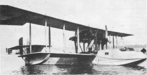
By July 1916 first examples of a larger Curtiss flying boat design began arriving in England. Designated H.8, these were quickly modified to accept more powerful twin 250 hp Rolls Royce engines, and redesignated Curtiss H.12s, or ‘Large Americas’. Although the lightly constructed hull was easily damaged in rough seas, the Large America was extensively used by the R.N.A.S. for anti submarine, anti Zeppelin and general reconnaissance duties.
Engines: 2 x 345 h.p. Rolls Royce Eagle. Length 46.1 ft (14.03 m) Wingspan 95 ft (28.96 m) Weight empty 7,360 lb (3,340 kg) Crew: 4 Armament: Five or six machine guns Bomb load: 4 x 230 lb (100 kg). Max speed: 100 mph (160 kph) Ceiling: 12,500 ft (3,800 m) fully loaded
The 1914 Model N was a two-seat biplane similar to the Model J, differing in the airfoil and placement of the ailerons, which were mounted between the wings. It was powered by a 90-100 hp Curtiss OX inline engine. Due to legal issues with the Wright brothers over the use of ailerons, the sole Model N was modified by locking the ailerons and increasing dihedral to seven degrees in an effort to prove that aircraft could be flown without ailerons or wing warping. The Curtiss N Army trainer featured tandem “bathtub” cockpits, trailing interplane ailerons, and cost $7,500. One was delivered on 11 December 1914 (AS35) for Army evaluation but was judged very unstable despite added dihedral. A design merger with the Model J led to the famed JN-4 “Jenny.”
Four 1916 N-8 (Model 1D) variant with 41’9″ wing and standard ailerons were built; AS60-AS63.
The first flight of the Model N took place in 1915. The United States Army purchased the aircraft for evaluation, but Curtiss repossessed it due to legal issues with the Wright brothers.
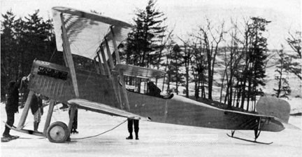
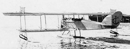
Developed in late 1916, the N-9 (Model 5) enlarged N was the seaplane version of the JN Jenny. To make the conversion, a single large central pontoon was mounted below the fuselage, with a small float fitted under each wingtip. It had a heavier engine than the Jenny to compensate for the extra weight of the floats and an upper wing that was some 10 feet (3 meters) longer than the lower one. Further modifications to the standard Curtiss JN-4 design were required to cope with stability problems that emerged in the N-9. They included lengthening the fuselage, increasing the area of the tail surfaces, and installing stabilizing fins on the top of the upper wing. The N-9 was initially powered by a 100-horsepower Curtiss OXX-6 engine. The U.S. Navy made use of wind tunnel data developed at the Massachusetts Institute of Technology in its redesign the JN-4. The N-9 was the first U.S. Naval aircraft to incorporate wind tunnel data directly into its design.
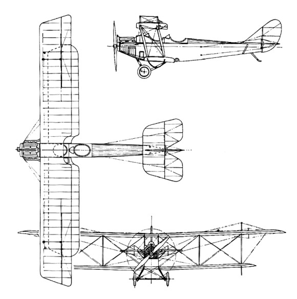
N-9H
The one model N built for US Army was later rebuilt as Model O with side-by side seating.
The Curtiss Aeroplane and Motor Company of Garden City, N.Y., received a Navy contract for thirty N-9s in August 1916. Another fourteen were ordered by the U.S. Army, as it was also conducting seaplane operations at that time. The 100-horsepower N-9 was satisfactory for pilot training, but it lacked the performance needed for bombing operations and gunnery training. To meet these requirements, Curtiss replaced the OXX-6 with a 150-horsepower Hispano-Suiza, then being manufactured under license in the United States by the Simplex Division of the Wright-Martin Company, and later by Wright Aeronautical Corporation. This improved model was designated N-9H.
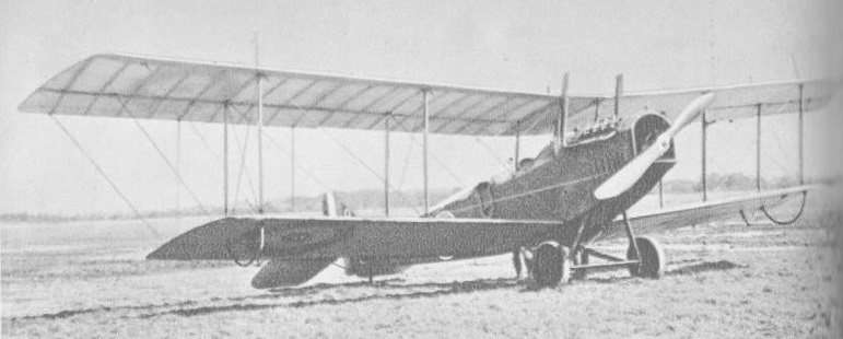
Curtiss N-9
A total of 731 were built; 122 by Curtiss (A60-A65, A85-A90, A96-A125, A201-A234, A294-A301, A342-A373, A2285-A2290), plus 681 subcontracted to Burgess Company of Marblehead, Massachusetts and also seen as Burgess N-9 (A409-A438, A999-A1028, A2351-A2572, A2574-A2650), and 50 by NAS Pensacola (A6528-A6542, A6618-A6632, A6733-A6742, A7091-A7100) from spare components and engines.
Although the consensus in early 1917 among aviators and even the N-9’s manufacturer was that the N-9 could not be looped, the pioneering early United States Marine Corps aviator Francis Thomas Evans, Sr., believed it was possible. On 13 February 1917, he flew an N-9 over the Gulf of Mexico off Pensacola, Florida, and began attempts to loop it. He succeeded on his fourth try, becoming one of the first persons ever to loop a seaplane (first pilot to loop a seaplane was Polish aviator Jan Nagórski on 17 September 1916 in Grigorovich M-9 flying boat). Lacking witnesses, he flew over Naval Air Station Pensacola and repeated the feat. In 1936, he received the Distinguished Flying Cross for this achievement. More important, however, were the stall and spin recovery techniques he discovered while flying the N-9 that day. During his first three loop attempts, the N-9 stalled before he reached the apex of the loop and fell into a spin. He found that by releasing back-pressure on the stick and aggressively applying opposite rudder to the direction of the spin he could change the spin into a normal dive and recover, something previously thought impossible in an N-9.
During the war, 2,500 Navy pilots were trained on the N-9. In addition to training a generation of Navy pilots, the N-9 was used to develop tactics for ship-borne aircraft operations in 1916 and 1917, using catapults mounted on armored cruisers. After the war, the N-9 was again employed to successfully demonstrate a compressed air turntable catapult. This type of catapult was later installed on battleships, replacing turret-mounted platforms for launching aircraft. In July 1917, several N-9s were acquired by the Sperry Gyroscope Company and were used as test vehicles for aerial torpedo experiments conducted for the Navy’s Bureau of Ordnance. The N-9 was withdrawn from the U.S. Navy inventory in 1927 after ten years of service.
The Brazilian Naval Aviation also operated the N-9H.
The Murray-Carnes was an all-steel development of the Curtiss N-9 requested by secretary Daniels of the Navy Department in 1918 from the J.W. Murray Mfg. Co. of Detroit.
The Hewitt-Sperry Automatic Airplane was a project undertaken during World War I to develop a flying bomb, or pilotless aircraft capable of carrying explosives to its target. Elmer Sperry, succeeded in arousing the US Navy’s interest.
After the US declaration of war on Germany, Sperry began urging the Navy to revisit the idea. The Naval Consulting Board supported him, and formally requested the Secretary of Navy to apportion $50,000 for the work. The government thus included the development of the flying bomb or aerial torpedo in its war preparations. The Senate went so far as to establish two classes for the type weapon, one for wireless control, the other for completely automatic operation. Final approval came on May 17, 1917, and the Navy agreed to provide five (later upped to seven) Curtiss N-9 seaplanes and to purchase six sets of the Sperry automatic control gear. Navy Secretary Josephus Daniels agreed to spend $200,000 on the project, with the money to be administered by the Bureau of Ordnance, the Bureau of Construction and Repair and the Bureau of Engineering. The operation was established at Copiague, Long Island.
In 1913, the Navy provided a flying boat to test and evaluate the gyro-based autopilot. Sperry’s son Lawrence served as an engineer during the test phase. In 1914, Lawrence Sperry was in Europe and observed the developing techniques of aerial warfare, including the use of aircraft. In 1915, the New-York Tribune broke the news of the project. In 1916, the two Sperrys joined Peter Hewitt, an early inventor of radio-related devices, to develop an explosive-laden pilotless airplane.
The system consisted of a gyroscopic stabilizer, a directive gyroscope, an aneroid barometer to regulate height, servo-motors for control of rudders and ailerons, and a device for distance gearing. These all could be installed in an airplane which could be catapulted or flown from the water, and would climb to a predetermined altitude, fly a pre-set course, and after traveling a pre-set distance, drop its bombs or dive to the ground. Wilkinson reported that the weapon did not possess a degree of accuracy sufficient to hit a ship, but, because of its range of 50 to 100 miles (80 to 161 km), it might be of interest to the Army.
The autopilot equipment was already designed, but the radio control system hadn’t been fully developed, so while the hangars were being built at Copiague, Sperry turned his attention to this aspect, purchasing rights to a number of patented radio-related inventions. Ultimately, though, the radio control systems were not used on the Hewitt-Sperry Automatic Airplane. Later, in 1922, the system was installed on several Verville-designed planes along with gear for the Army Air Services engineering division. These aircraft successfully hit their targets from ranges of 30, 60 and 90 miles (140 km).
The first test flights of an autopilot-equipped aircraft was in September, 1917, and took place with a human pilot on board to fly the takeoff. By November, the system successfully flew the aircraft to its intended target at a 30-mile (48 km) range, where the distance-measuring gear would drop a bag of sand. Accuracy was within two miles (3 km) of target.
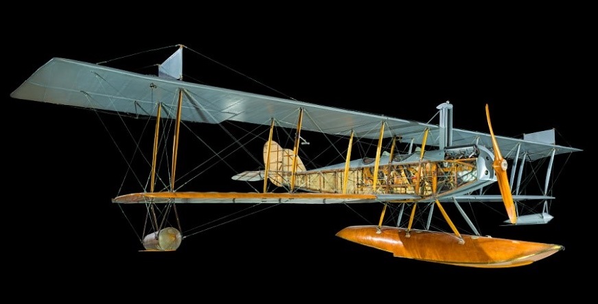
When the N-9 flight test program got started, it became apparent that a more efficient airframe was needed. Because war production deliveries could not be diverted, a special, rush order was placed with Curtiss in October, 1917, for six planes of unique design, with an empty weight of 500 lb (230 kg), top speed of 90 mph (140 km/h), range of 50 miles (80 km) and the capability of carrying up to 1,000 lb (450 kg) of explosives. They became known as the Curtiss-Sperry Flying Bomb. Because this was to be a design dedicated to the remote control concept, the planes were not equipped with seats or standard pilot controls.
Only one example of the type has survived, and is now a part of the National Air and Space Museum collection. Originally on display at the Museum of Science and Industry in Chicago, Illinois, it was later transferred back to the U.S. Navy pending transport to the National Air and Space Museum. The Naval Air Engineering Laboratory in Philadelphia, Pennsylvania, fully restored it in 1966.
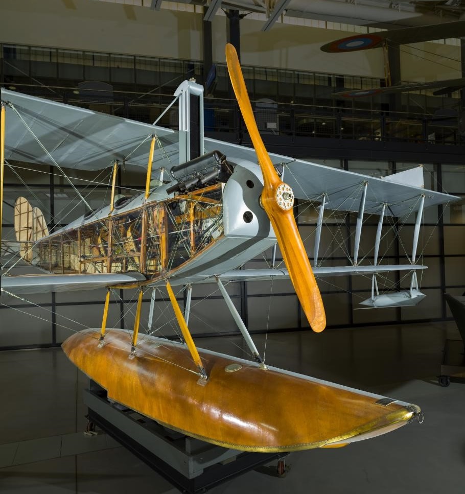
N / N-9C Original N-9, later known as the N-9C. Engine: Curtiss OXX-3, 100hp (75 kW) Wingspan: 38’3″ Length: 27’2″ Speed: 70 mph Seats: 2
N-8 Production version of N for US Army, Equivalent to JN-3. Engine: 90 hp (67 kW) Curtiss OX-2 Four built 1915
N9-H Engine: Wright-Hisso, 150 hp (110 kW) Propeller: 2-bladed fixed-pitch wooden Wingspan: 16.2 m (53 ft 4 in) Wing area: 496 sq ft (46.1 sq.m) Length: 9.4 m (30 ft 10 in) Height: 3.3 m (10 ft 9 in) Weight: Empty weight: 973 kg (2,140 lb) Gross weight: 1,257 kg (2,765lb) Useful load: 625 lb Maximum speed: 78 mph (126 km/h, 68 kn) Cruise speed: 70 mph Service ceiling: 6,600 ft (2,000 m) Time to 3,240 ft (990 m): 10 minutes Range: 180 mi Seats: 2
In 1914 Curtiss lured B. Douglas Thomas from Sopwith to design the Model J trainer, which lead to the JN-4. The JN-4 was developed from the JN-2, via the interim JN-3 which had featured unequal-span wings with ailerons on the upper wing only and introduced a wheel-type aileron control system. Redesigned vertical tail surfaces had a fin and rudder assembly with contours which were to be largely retained in the JN-4. The UK bought 91 JN-3s and the US Army two. Several JN-2s were converted subsequently to JN-3 standard by the incorporation of JN-3 wings and vertical tail surfaces and by installation of the 75kW Curtiss OXX engine. Total production was no more than 100, a dozen built at a newly-built Toronto factory.
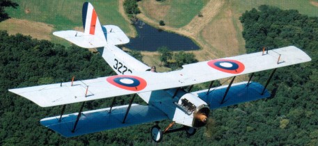
The JN-4 in its original form closely resembled the JN-3, retaining the same unequal-span two-bay wing and cross-axle landing gear. It first appeared in July 1916 when 105 were sold to the UK and 21 to the US Army. Others were purchased by private owners and a number were operated by the Curtiss company’s flying schools. As a result of British experience with the JN-3 and JN-4 the Curtiss company developed the JN-4A (retro-designated Model 1 in 1935), which incorporated a number of improvements (larger tailplane and engine downthrust). A total of 781 was completed, 87 of them at the Curtiss Canadian factory. The US Army bought 601, the US Navy five and the rest were exported to the UK. The JN-4B (Model 1A) appeared in late 1916, just before the JN-4A. It differed in several design details (it introduced-the larger tailplane and used the OX-2 engine), and found a number of private purchasers and flying schools as customers, added to which the US Army bought 76 and the US Navy nine. Two examples of the experimental JN-4C were followed by the very successful JN-4 Can and JN-4D (Model 1C). The JN-4 Can had been developed from the JN-3 by the Curtiss company’s Canadian associate, Canadian Aeroplanes Limited, and soon became known as the Canuck. Production totalled 1,260 of which 680 went to the US Army while the bulk of the remainder became the standard Canadian primary trainer. The JN-4 Can served with the Royal Canadian Air Force until 1924, while privately owned aircraft remained in use into the 1930s. John Ericson, chief engineer of Canadian Aeroplanes Ltd, assembled 127 aircraft in 1927, most of them reconditioned aircraft incorporating many parts which had been held in stock. Some had a third cockpit and were known under the designation Ericson Special Three.
The Curtiss JN-4 two-seat biplane soon acquired the nickname ‘Jenny’ which was used widely during the inter-war years. It was one of the most significant American aircraft of its time. From April 1917 when the USA entered World War I it was built in large numbers and used to train some 95% of all American and Canadian pilots. It achieved renewed fame from 1919 until the late 1920s, when thousands were flown in the barnstorming era, thrilling spectators at travelling aerial pageants and shows throughout the United States.
JN-4H
The JN-4D appeared in June 1917 and went into large-scale production, 2,812 being built between November 1917 and January 1919. With an urgent need for efficient trainers in wartime conditions the production involved six other US manufacturers.
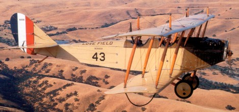
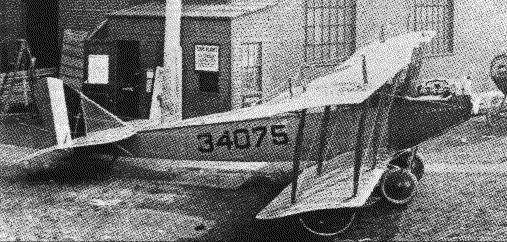
The St. Louis Aircraft Corporation became one of six across the country to produce the Curtiss JN 4D Jenny with first deliveries in 1918. The first order was for 200 planes, the company delivered 30 aircraft per month, and 57 JN 4D October 1918. The St. Louis Car went on to manufacture 450 JN-4D Jenny trainers for the U.S. Army.
JN-4D Army trainer set up for publicity photos outside St. Louis Aircraft plant in 1918
As well as several new features, the JN-4D combined the more successful elements of both the JN-4 Can and JN-4A designs (stick control of the former, in place of the Deperdussin system, and the lines and engine downthrust of the latter). The end of World War I led to cancellation of contracts for 1,100 examples of a JN-4D-2 version, which had a number of modifications requested by the US Army. In the event, only the prototype was delivered to the military authorities, although several were sold to civil operators in 1919. In a bid to provide an advanced trainer to meet urgent wartime needs, the JN-4D was re-engined with the more powerful 112kW (150-hp) Hispano-Suiza built by the Wright company. The resulting JN-4H (Model 1E) was in production from the end of 1917 to the November 1918 armistice, 929 being delivered to the US Army. The JN-4H was completed also in dual-control (JN-4HT), combing (JIM-4HB) and gunnery trainer (JN-4HG) versions. The one-off JN-5H advanced trainer was built to a US Army requirement, but was rejected in favour of the Vought VE-7. It was developed into the JN-6H (Model 1F) which had a strengthened aileron control structure. The US Army purchased 1,035 JN-6Hs, subsequently passing five examples to the US Navy. The aircraft delivered to the US Army were built in sub-variants specialised for various training functions. (JN-6HB single-control bomber trainer, JN-6HG-1 dual-control trainer, JN-6HG-2 single-control gunnery trainer, JN-6HO single-control observation trainer and JN-6HP single-control pursuit [fighter] trainer). With the armistice the production was stopped, after more than 6000 were produced, mostly of the “D” model. As part of the post-war economy drive the US Army was forced to modernize the ‘Jenny’ rather than purchase new designs. This task was allocated to US Army Service Depots, which upgraded many of the earlier versions until 1926. The revised aircraft all used Wright-built 134kW Hispano-Suiza engines and were redesignated JNS (standing for JN Standardized). Between 200 and 300 JNS trainers were completed. The US Army used JN-4As, JN-4Ds and JN-4 Can primary trainers until 1919. The higher powered JN-4Hs and JN-6Hs remained in service until they were phased out in favour of new types in the mid-1920s, the last Jennies being withdrawn from US Army service in 1927.
Tallman & Mantz Jenny movie line-up in Navy markings
From 1919 onwards Jennies had been sold to private owners, many who used their aircraft as stunt pilots in travelling circus or barnstorming. The Jenny also featured in many Hollywood films of the 1920s and early 1930s. A considerable number of Jennies survive in museums and several in private ownership are maintained in flying condition in the USA.
Curtiss JN-4D Engine: 1 x 67kW, 90 hp Curtiss OX-5 inline piston Max take-off weight: 871 kg / 1920 lb Empty weight: 630 kg / 1389 lb Wingspan: 13.30 m / 43 ft 8 in Length: 8.33 m / 27 ft 4 in Height: 3.01 m / 9 ft 11 in Wing area: 32.70 sq.m / 351.98 sq ft Max. speed: 121 km/h / 75 mph Cruise speed: 97 km/h / 60 mph Ceiling: 1980 m / 6500 ft Range 200 miles / 320 km Seats: 2
Curtiss, who was a motorcycle fiend and engine genius, had actually asked the Wright Brothers if they wanted one of his 50 hp engines when he went to discuss some aviation data, but they said no, unaware that Curtiss and the AEA would soon be a major competitor.
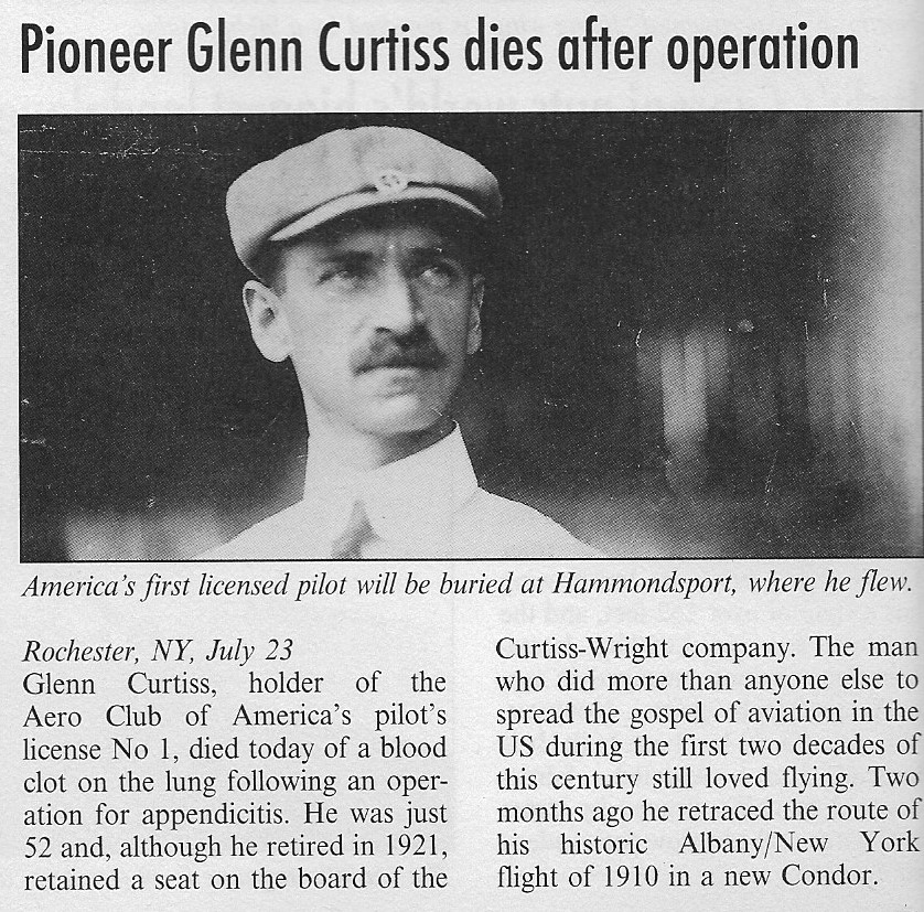
As a member of Alexander Graham Bell’s Aerial Experiment Association (AEA), Glenn Curtiss built the engines for the Red Wing and the White Wing early in 1908, piloted his first plane, and built and flew the June Bug that June.
The AEA disbanded in 1909, and Curtiss formed the Herring-Curtiss Company on 20 March 1909 with Augustus Herring. Its first customer was the Aeronautic Society of New York. Curtiss delivered his first plane to them, the Curtiss No. 1, built to their specifications, on May 29, 1909.
When the Herring partnership split up, Curtiss founded the Curtiss Exhibition Company, the Curtiss Aeroplane Company in December 1911 in Hammondsport, New York, and the Curtiss Motor Company.
As business expanded, the Hammondsport factory became unable to fill all the orders. Curtiss extended its operation to Buffalo, where it rented the site of the company that had supplied Curtiss with his first bicycle engine years before. Curtiss also opened a new plant in Toronto. The quarters in Buffalo quickly became inadequate, and a new 120,000-square-foot (1,115-square-meter) building was constructed that became the company headquarters. Soon after, a new plant that sprawled over 72 more acres was added.
1909-early 1911 – While A, B, and C models are known (or thought) to have existed during this historically important period for Curtiss, where they were applied is not. Numerical assignments, as well, were guesses—Model 2 has appeared for both Rheims Racer and Charles Willard’s Banshee Express but not verified (Willard unjustifiably claimed authorship of that design). By 1910, Model D had been established, in some references tied to Curtiss-Herring, which was actually built after the partners’ dissolution. But there were at least 9 aircraft known to have been produced in this period, the “official” Model D, in one of its many forms, formally appeared in the first company catalog on mid-1911 along with its companion Model E. Production of concurrent Curtiss-Aero Society Model Ds unknown but the design quickly evolved into the Curtiss D (Standard). A Herring-Curtiss, for which plans were published for home-builders of the time, differed from Curtiss D with its ailerons on the front wing struts instead of the rear wing struts. Herring’s contribution, besides that as a temporary partner, was his alleged invention of a gyroscopic stabilization device (claimed, but unsubstantiated, 1909 US patent #12,256), which would circumvent the Wright’s aileron patents, but which was never used on any Curtiss machine.
Curtiss designed and built the following planes during 1908 – 4, 1909 – 2, 1910 – 4, 1911 – 5, 1912 – 3, 1913 – 3, total – 21.
In 1916, the Curtiss Aeroplane & Motor Company, Ltd. went public with Curtiss as president. By that time Curtiss had become the world’s largest aviation company, employing as many as 18,000 at Buffalo and 3,000 at Hammondsport.
The Curtiss Aeroplane and Motor Company was created 13 January 1916 from the Curtiss Aeroplane Company of Hammondsport, New York and Curtiss Motor Company of Bath, New York. Burgess Company of Marblehead, Massachusetts, became a subsidiary in February 1916. In 1916 the company moved its headquarters and most manufacturing activities to Buffalo, New York, where there was far greater access to transportation, manpower, manufacturing, and much needed capital. It became the largest aircraft manufacturer in the world during World War I, employing 18,000 in Buffalo and 3,000 in Hammondsport, New York. Curtiss produced 10,000 aircraft during that war, and more than 100 in a single week. A third factory (Garden City, Long Island, NY) became boat hull department for flying-boat production. Burgess Company of Marblehead, Massachusetts, became a subsidiary in February 1916. Aircraft built during First World War included A and AH biplanes for USN, Models D and E for U.S. Army, Model F flying-boats for USN, H-4 Small Americas, H-12 Large Americas and H-16 Large Americas (plus 150 by Naval Aircraft Factory). Best-known were JN-4/JN-6 “Jenny” trainers (5,000 built, plus 1,200 by Canadian Curtiss), HS flying-boats, MF flying-boats, N-9 floatplanes, British S.E.5a fighters, Orenco D fighters, and 5L flying-boats. Total wartime was 4,014 aircraft and 750 aero engines.
After the war, Curtiss, fell on hard times. In August 1920, the company was forced into receivership. Clement Keys, a Canadian financier, obtained funds to manage the company’s debt and led it again to sound financial status. The Buffalo facility became the major facility, and the company remained the largest U.S. aircraft company through the 1920s.
Postwar production, mostly in 1920s, included NC- 1/2/3/4 transatlantic flying-boats (four only); Oriole, Eagle, and Seagull civil types (little success achieved with the few built). Followed by a series of Army (R-6/R-8 etc.) and Navy (CR/R2C/R3C etc.) racers. Twelve B-2 Condor biplane bombers were followed by PW-8 biplane fighters, P-1/P- 6 U.S. Army Hawks, F6C U.S. Navy Hawks, and O-1/11/39 and A-3 Falcons for U.S. Army. The few Carrier Pigeons and Larks were followed by one Tanager biplane, which won 1929 Guggenheim Safe Airplane Competition. Subsequently produced N2C Fledgling, F8C/OC Falcon, and F8C/02C Helldivers for USN.
Foundation of Curtiss-Robertson division in 1928 was followed by, on July 5, 1929, Curtiss Aeroplane and Motor Company became part of Curtiss-Wright Corporation, together with 11 other Wright and Curtiss affiliated companies. In 1929, shortly before Curtiss died, the Curtiss Aeroplane & Motor Company, Ltd., merged with the Wright Aeronautical Corporation to form the Curtiss-Wright Corporation.
1930
Neither Curtiss or Wright successfully made the transition to the jet age and substantially all aircraft assets were sold to McDonnell and North American by 1950.
UK Cunard built factory at Aintree late 1917/early 1918 after receiving contract on November 22,1917 to build 500 Bristol Fighters. Production began March 1918, although in the previous month factory had been taken over by Ministry of Munitions and renamed National Aircraft Factory No 3. Production ended after only 126 aircraft completed.
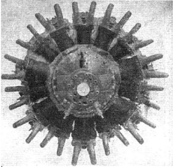
Designed by Roy Fedden of Cosmos Engineering and built at Bristol by Brazil-Straker under the direction of Roy Fedden, and first run in July 1917. The Cosmos Mercury fourteen-cylinder twin-row air-cooled radial Mercury featured an unusual crankshaft and connecting rod arrangement that dispensed with the more normal design of a single master rod linking to individual rods for each cylinder. It produced 347 horsepower (259 kW). It was said to run well without vibration and set an unofficial time to climb record while fitted to a Bristol 21A Scout F.1, the aircraft achieving 10,000 ft (3,000 m) in 5.4 minutes and 20,000 ft (6,000 m) in 16.25 minutes.
An Admiralty order for 200 engines was placed in 1917 but was later cancelled by Lord Weir due to the end of World War I, it is also stated that Lord Weir had a preference for the ABC Dragonfly. It did not enter production.
The name was re-used by Fedden for the later nine-cylinder Bristol Mercury radial engine.
Mercury Type: 14-cylinder air-cooled two-row radial engine Bore: 4.375 in (111.1 mm) Stroke: 5.8 in (147.3 mm) Displacement: 1,223 cu in (20.0 l) Diameter: 41.625 in (1,057.3 mm) Dry weight: 587 lb (266 kg) Valvetrain: 3 poppet valve per cylinder; 2 exhaust and 1 inlet Fuel type: Petrol Oil system: Pressure feed to main bearings Cooling system: Air-cooled Power output: Normal: 315 hp (235 kW) at 1,800 rpm at sea level, Maximum: 347 hp (259 kW) at 2,000 rpm at sea level Compression ratio: 5.3:1
The 1917 Cleveland 4 six-cylinder aero-engine designed by Walter C Willard was a 150hp 706.86ci air-cooled radial. Unique concept of each piston operating a bevel gear, which in turn meshed with a main gear to drive the propshaft. Also reportedly produced as 140hp.
Clerget are best known for their well engineered rotary engines produced from 1911 to the end of World War I in 1918, the first of their type to deliver fuel-air mixture to the cylinder heads by external induction tubes via externally push rod operated inlet valves. They later made a series of static radial aircraft diesel engines. The experimental 16X was a departure from all of these, first run in 1918. Despite contemporary descriptions as a radial engine, it was in more modern terms an X-type, four stroke water-cooled petrol engine, essentially two 90° V-8 cylinder engines, one inverted, coupled to a common output shaft.
Type: 16-cylinder X-type piston engine, with four 4-cylinder banks separated by 90°. Single sparking plug on the upper side of each cylinder. Bore: 130 mm (5.1 in) Stroke: 130 mm (5.1 in) Displacement: 27.6 l (1,684.26 cu in) Length: 1,306 mm (51.42 in) Diameter: 512 mm (20.16 in) Dry weight: 340.2 kg (750 lb) Valvetrain: Two overhead valves per cylinder, each operated via a long push-rod worked by one camshaft per cylinder bank. Side inlet and exhaust ports. Fuel system: Separate carburettors mounted between upper and between lower cylinder bank, each feeding their pairs of banks. Single sparking plug in upper side of each cylinder. Fuel type: Petrol Cooling system: Water, centrifugally pumped. Power output: 313 kW (419.74 hp) at 1,600 rpm Compression ratio: 5:1 Fuel consumption: 0.48 l/kW/h (0.079 imp gal/hp/h; 0.095 US gal/hp/h) Oil consumption: 0.038 l/kW/h (0.0063 imp gal/hp/h; 0.0076 US gal/hp/h)
The Clerget 11Eb was an 11-cylinder rotary aircraft engine of the World War I era designed by Pierre Clerget. Powering Sopwith types it was nominally rated at 200 horsepower (150 kW). First run in 1918, the unit cost was £1,663.