Operated aircraft works and flying school at Gotha and seaplane school at Warnemunde in First World War. Manufactured large quantities of aircraft during the war, including seaplanes and twin-engine bombers. Closed by Versailles Peace Treaty. Reopened in mid-1930s with two-seat training biplane, Go 145. In Second World War built Bf 109 fighter and Do 17Z bomber, also Go 242 glider and a powered version designated Go 244.
World War 1
Gosport Aircraft
UK
Formed in early part of First World War at Gosport, Hants. Built flying-boats, mainly Norman Thompson FBAs plus some Porte/Felixstowe F.5s.
Goodyear ‘C’ Class
The BA contract was followed by others for C and D Class ships, each slightly larger and more improved than the preceding type.
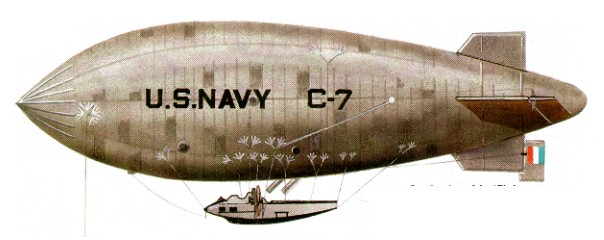
The Goodyear ‘C’ class airship was a type which must be counted the most successful design ever produced for the type of work envisaged: the C-7 became part of technical history and the type as a whole, although of non-rigid pattern, influenced the next generation of rigid vessels.
The first flight of a ‘C’ class airship took place on 30 September 1918, this and the subsequent five airships being produced by the Goodyear Tire & Rubber Company of Akron, Ohio, where a training establishment and a hydrogen plant had already been set up under contract with the US Navy on 29 May 1917; the 20 trainees in each intake had the advantages of permanent barracks.
The six vessels produced were numbered C-1 to C-8, the omitted designations C-2 and C-6 being used for some reason with C-9 and C- 10 for the quartet of airships of the type ordered from the Goodrich company.
Although the work performed by the ‘C’ class units proved it an outstanding airship design, the type came into use at a time when World War I was nearing its end, so it is to the design features of the class that one must look for interest. Most obvious of these was the four-crew streamlined car with an engine and pusher propeller mounted at each side. The C-7’s claim to history rests on a single incident when, on 1 December 1921, it became the first airship in the world to fly with helium substituted for the normal hydrogen lifting gas. The test was so successful that it was decided that henceforth all US airships would use this inert gas as a fire precaution despite the small loss of lift in comparison with that provided by lighter but inflammable hydrogen.
Other records held by the ‘C’ class include its use for the first successful release of an aeroplane from a non¬rigid airship, and by becoming the first airship to make a coast-to-coast US crossing, this being achieved by one of the pair that were given over to US Army control in 1921. On the other hand the C-5, earmarked for a projected transatlantic crossing attempt, was lost in a storm when it was ripped from its moorings.
With the end of the war, large contracts for naval airships were cancelled but work continued on various military designs.
Goodyear C-7
Type: coastal patrol and convoy escort airship.
Powerplant: two 149. 1-kW (200-hp) Hall-Scott L-6 eight-cylinder water-cooled piston engines; reports also mention the 11 1.9-kW (150 hp) Wright Hispano
Maximum speed 97 kph (60 mph)
Service ceiling 2438 m (8,000 ft)
Range about 4828 km (3,000 miles).
Useful lift about 2,404 kg (5,300 lb).
Diameter 12.80 m (42 ft 0 in)
Length 58.52 m (192 ft 0 in)
Volume 5125.3 cu.m (181,000 cu ft)
Armament: one 7.62-mm (0.30-in) Lewis machine-gun.
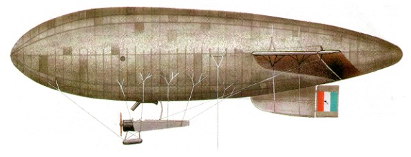
Goodyear Type F / ‘B’ Class
It was in 1915 that the US Navy took on charge its first non-rigid coastal patrol airship, a type that was based on the information coming out of Germany and built by the Connecticut Aircraft Company as the DN-1. The ‘B’ class which followed the failure of this first design was more closely based on that of British airships used for similar work, the first orders going to Goodyear on 14 March 1917 for 9 B Class airships of 77,000 cu ft (Goodyear Type F and FA). However in all fairness it should be said that the ‘B’ class was in no way conceived as a replacement for the earlier type, which had in fact not flown when de-sign work had begun on the Goodyear.
Although the ‘B’ class shared some of the British features, such as the use of an aeroplane fuselage as its car, there were differences such as the absence of an upper fin, though some ‘B’ class vessels did have this feature. There were several other differences be¬tween individual airships within the same class. The company’s first complete airship, BA, was delivered on July 19, 1917. This contract was followed by others for C and D Class ships.
Further variations took place after the first nine examples (B-1 to B-9) had been built by Goodyear, production then being undertaken by the B. F. Goodrich Co. The earlier airships had employed the finger-patch method of fastening the car lines to the envelope, which measured 9.60 m (31 ft 6 in) in diameter, and 48.77 m (160 ft 0 in) in length, but the ‘B’ class from B-10 to B-14 were longer and of greater girth.
It is interesting to note that the later variants (of which two only were built by Connecticut) were the shortest of all but with a greater-diameter envelope, and that the belly-bands which had replaced the finger-patches on the Goodrich were retained.
The B-10, in common with others of its class, proved a sound and reliable vessel; the two-man crew were fairly comfortably accommodated in the individual cockpits of the suspended fuselage, on which the landing gear had been replaced by rigidly-mounted air-filled flotation bags.
The B-10 was among the first batch of Goodyear/Goodrich vessels which were delivered between June 1917 and July of the following year, the former date marking something of a record since the first of the ‘B’ class had made its maiden flight at the end of May, only two weeks after the declaration of war on Germany by the United States. The total number of vessels of this type delivered was only 16, but three were later reconstructed and given new numbers B-17 to B-19. The final B-20 was sufficiently different, with increased gas capacity and an OXX-3 motor, to be considered a new design.
The Goodyear B-20 had an increased cubic capacity, and the rope lines of earlier models were replaced by cable. Three fins were fitted instead of the five of the early variants, although the car with its typical Avro 504-type lines was unchanged.
Goodrich B-10
Type: coastal patrol airship
Powerplant: one 74. 6-kW (100-hp) Curtiss OXX-2 eight-cylinder water-C cooled piston engine
Maximum speed 80 kph (50 mph)
Service ceiling 2134 m (7,000 ft)
Endurance about 16 hours.
Useful lift about 2268 kg 1 (5,000 lb)
Diameter 10.06 m (33 ft 0 in)
Length 50.90 m (167 ft 0 in)
Volume 2265.3 cu.m (80,000 cu ft)
Armament: one or two 7.62-mm (0.30-in) Lewis machine-guns.
Goodyear Tyre & Rubber Co.
Airship work started at the Akron, Ohio, plant of the company in 1910, when engineer P. W. Litchfield began developing the specialised techniques required for the manufacture of rubberised fabric. After visiting Europe to see the latest airships flying at the time, he returned to America to start the construction of the company’s first envelope, which was completed in July 1911. With a total capacity of 375,000 cu ft, it was made for Melvin Vaniman’s ill fated airship “Akron” which attempted to fly across the Atlantic in July 1912.
As a result of negotiations, which began in 1922 between Goodyear and Luftschiffbau Zeppelin, the Goodyear-Zeppelin Corporation was formed on December 14, 1923. From then on, Goodyear’s major effort was directed towards the design of rigid airships for naval and commercial use, but it was to be several years before an airship of this type was laid down by the, new company.
“GZ” stands for Goodyear-Zeppelin, stemming from the partnership Goodyear had with the German company when both were building airships together. However these models came many years after this partnership had dissolved during the start of World War II. The GZ-1 was the USS Akron (ZRS-4), the U.S. Navy’s fourth rigid airship used for several tests including as a flying “aircraft carrier”.
Total airship production by the company up to 1923 was 37, of which 26 were for the U.S. Navy, 7 for the U.S. Army, and 4 commercial.
On December 5, 1939, to reflect the company’s growing interest in other fields of aeronautical work, the corporate name was changed again, this time to the Goodyear Air¬craft Corporation. With America’s entry into WW II, a great expansion began of the U.S. Navy’s airship service, with 200 airships being authorised in June, 1942. Between September, 1941 and April, 1944, Goodyear delivered 130 K Class, 10 L Class, 7 G Class, and 4 M Class airships to the Navy. These joined 4 K, 3 L, 1 G, and two ex Army ships already in service, plus five Goodyear fleet ships, to make the largest airship fleet ever assembled by any nation. They were used extensively along the eastern and western seaboards of the United States, in Central and South American waters, and from 1944 in the Mediterranean area. The ZP squadrons, the first being commissioned at Lakehurst on January 2, 1942, (ZP 12), were organised into Fleet Airship Wings, of which there were five.
As recently as 1967, Goodyear carried out an evaluation programme for the U.S. Naval Air Development Center in which a series of rigid and non rigid designs were examined for operational cost and performance potential. Amongst the designs considered were 45 million cubic feet rigids operating at speeds up to 210 m.p.h., which were found to be totally practical from a technical point of view.
As a further reflection of Goodyear’s expanding interest in aeronautics and space research, the company name was changed once more on July 1, 1963, to become the Goodyear Aerospace Corporation. With this change, airship operations were transferred to Goodyear Tire & Rubber public relations, with Aerospace being responsible for engineering, maintenance and development of the fleet. During this period the company were operating two airships, namely, the Type GZ 19As “Mayflower”, based at Miami, Florida, and “Columbia” at Los Angeles, California, during the winter months, both airships going on nationwide tour each summer. These ships were of 147,000 cu.ft. capacity and powered by two 175 h.p. Continental engines.
Goetze, Richard
Germany
Commandit Gesellschaft Richard Goetze founded in First World War with four factories in the Berlin area. Reputed to have built Otto biplanes.
Goedecker, Jacob
Small company at Niederwalluf-on-Rhine, built several Taube-type monoplanes prewar and Goedecker B trainer prototype in 1915. Also ran flying school. Closed at time of Versailles Peace Treaty.
Gnome-Rhône Omega / 7 Omega / 50 hp / 14 Omega-Omega / 100 hp
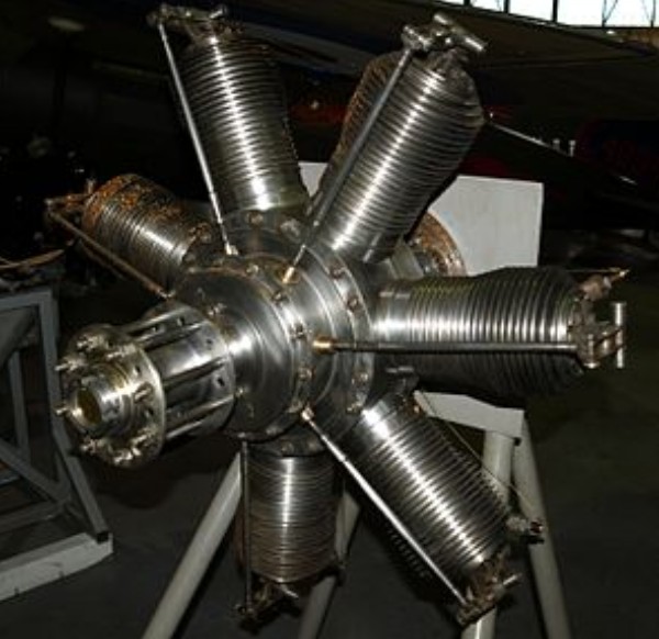
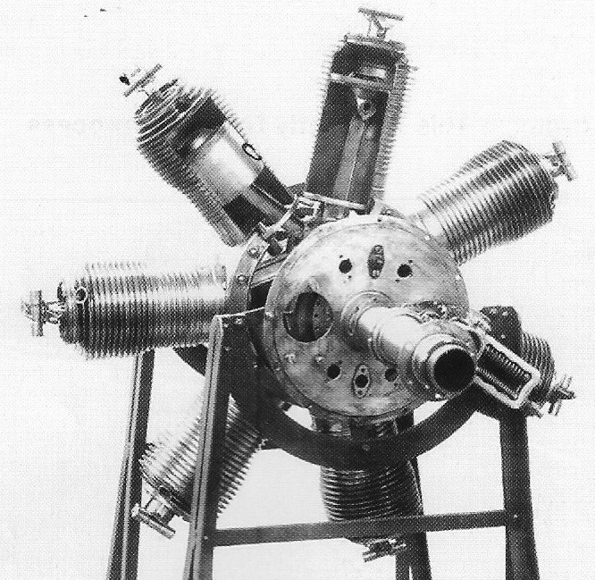
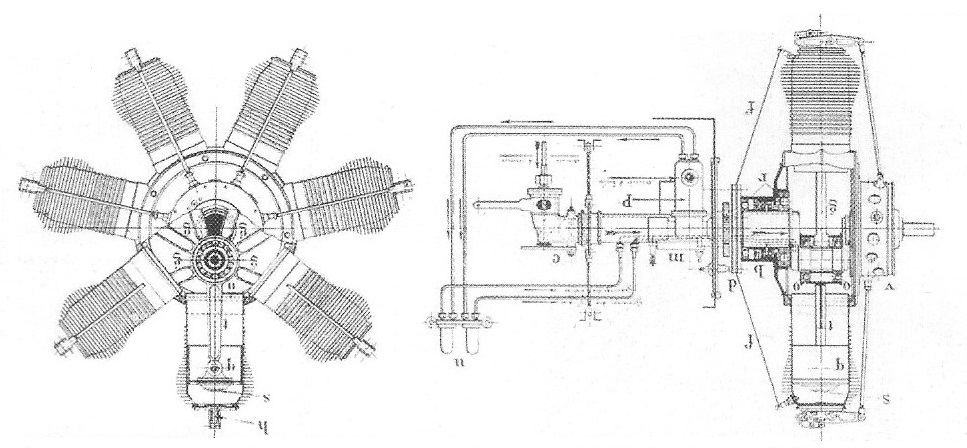
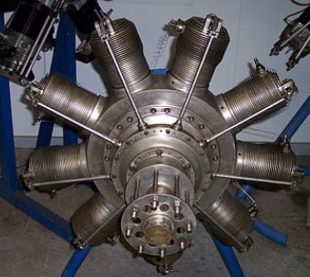
The Gnome 7 Omega (commonly called the Gnome 50 hp) is a French seven-cylinder, air-cooled aero engine. It was shown at the Paris Aero Salon held in December 1908 and was first flown in 1909. The unit cost in 1909 was £520.
It was the world’s first rotary engine produced in quantity, and its introduction revolutionized the aviation industry and it was used by many early aircraft. 4,000 had been produced until 1914 (more later). It produced 50 horsepower (37 kW) from its capacity of 8 litres (488 cubic inches).
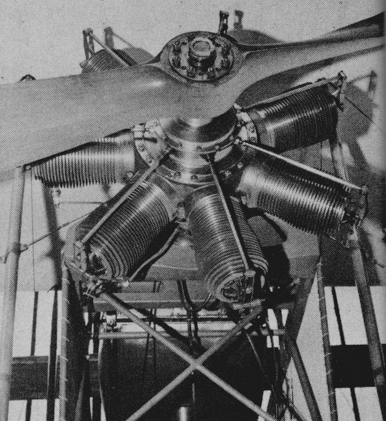
A Gnome Omega engine powers the 1912 Blackburn Monoplane, owned and operated by the Shuttleworth Collection, the oldest known airworthy British-designed aeroplane worldwide.
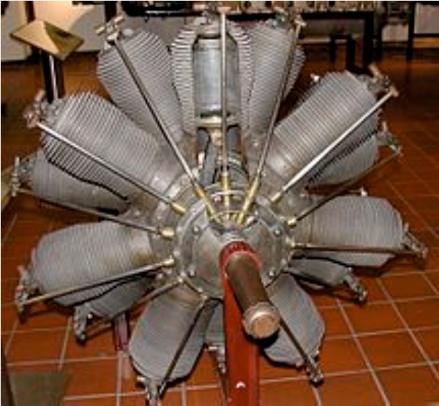
A two-row version of the same engine was also produced, known as the Gnome 14 Omega-Omega or Gnome 100 hp. The prototype Omega engine still exists, and is on display at the United States’ National Air and Space Museum.
Variants
Gnome 7 Omega
Single-row 7-cyl. original version; 50 hp (37 kW).
Gnome 14 Omega-Omega
Two-row, 14-cylinder version using Omega cylinders; 100 hp (75 kW).
Applications:
Gnome 7 Omega
Avro Type 500
Blackburn Mercury
Blackburn Monoplane
Blériot XI
Bristol Boxkite
Bristol Racing Biplane
Bristol Monoplane
Bristol-Prier P.1
Bristol-Coanda School Monoplane
Bristol-Coanda T.B.8
Burga Monoplane
Fabre Hydravion
Henry Farman Type Militaire
Grahame-White School Biplane
Koolhoven Heidevogel
Nieuport Monoplane
Paulhan Biplane
Pemberton-Billing P.B.9
Royal Aircraft Factory B.E.3
Royal Aircraft Factory B.E.4
Royal Aircraft Factory F.E.2
Short S.27
Short Tandem Twin
Short S.37 Tractor Monoplane
Short Triple Twin
Short S.47 Triple Tractor
Short S.62
Sopwith Bee
Sopwith Sparrow
Valkyrie Type B
Vickers No.6 Monoplane
Vickers No.7 Monoplane
Vickers Boxkite School Biplane
Gnome 14 Omega-Omega
Bristol Gordon England G.E.2
Coventry Ordnance Works Biplane 10
Nieuport Monoplane
Short S.41 Tractor Biplane
Short S.57 Seaplane
Short S.64 Folder Seaplane
Short S.74 Admiralty Seaplane
Specifications:
7 Omega
Type: 7-cylinder, single-row, rotary engine
Bore: 110 mm (4.3 in)
Stroke: 120 mm (4.7 in)
Displacement: 8 L (488.5 cu in)
Length: 79 cm (31 in)
Diameter: 84 cm (33 in)
Dry weight: 75 kg (165 lb)
Valvetrain: pressure-driven inlet valves were located on the pistons
Oil system: Total loss, castor oil
Cooling system: Air-cooled
Reduction gear: Direct drive, right-hand tractor, left-hand pusher
Power output: 37 kW (50 hp) at 1,200 rpm
Gnome-Rhône Monosoupape / 7 Type / 9 Type
The Monosoupape (French for single-valve), was a rotary engine design first introduced in 1913 by Gnome Engine Company (since 1915 called Gnome et Rhône). It used an arrangement of internal transfer ports and a single pushrod-operated exhaust valve to replace a large number of moving parts found on more conventional rotary engines, and made the Monosoupape engines some of the most reliable of the era. British aircraft designer Thomas Sopwith described the Monosoupape as “one of the greatest single advances in aviation”.
Produced under license in Britain the engine was built in large numbers in both seven and nine-cylinder versions, the latter being produced with two different displacements.
Contrary to the Le Rhône designs, earlier Gnome engines like the Gnome Omega, Lambda and Delta used a unique arrangement of valves in order to avoid needing pushrods and other complex devices that operated during the inlet phase of the combustion cycle on more conventional engines. Instead, a single exhaust valve on the cylinder head was operated by a pushrod that opened the valve when the pressure dropped at the end of the power stroke. A pressure-operated inlet valve, which was balanced by a counterweight to equalize the centrifugal forces, was placed in the centre of the piston crown, where it opened to allow the fuel–air charge to enter from the engine’s central crankcase.
Although ingenious, the system had several drawbacks: the cylinder heads had to be removed both in order to perform maintenance of the intake valve, which could easily become jammed, and in order to adjust the timing and pressures correctly for the rod-less operation; and the Gnomes exhibited even poorer fuel economy than other rotaries because the inlet valves opened at times that were not efficient.
In 1913, Louis Seguin and his brother Laurent (engineers who founded the Société Des Moteurs Gnome [the Gnome motor company] in 1905) introduced the new Monosoupape series, which eliminated the inlet valve, replacing it with piston-controlled transfer ports similar to those found in a two-stroke engine. Beginning with the power stroke, the four-stroke engine operated normally until the piston was just about to reach the bottom of its stroke (bottom dead center, or BDC), when the exhaust valve was opened “early”. This let the still-hot burnt combustion gases “pop” out of the engine while the piston was still moving down, relieving exhaust pressure and preventing exhaust gases from entering the crankcase. After a small additional amount of travel, the piston uncovered 36 small ports around the base of the cylinder, leading to the crankcase which held additional fuel–air mixture (the charge). No transfer took place at this point since there was no pressure differential; the cylinder was still open to the air and thus at ambient pressure. The overhead valve exhausted directly into the slipstream since there was no exhaust manifold in order to save weight.
During the exhaust stroke, total scavenging occurred as the air moving past the cylinder exterior lowered the pressure inside due to the direct exposure of the exhaust port to the slipstream. The piston continued its exhaust stroke until top dead center (TDC) was reached, but the valve did not close. The piston began to move down on its intake stroke with the valve still open, pulling fresh (presumably un-filtered) air into the cylinder. It remained open until it was two-thirds of the way down, at which point the valve closed and the remainder of the intake stroke greatly reduced the air pressure. When the piston uncovered the transfer ports again, the low pressure in the cylinder drew in the balance of the charge.
The charge was an overly rich mixture of air, which was acquired through the hollow crankshaft, and fuel that was continuously injected by a fuel nozzle on the end of a fuel line, entering the crankcase through the hollow crankshaft. The nozzle was in the proximity of, and aimed at, the inside base of the cylinder where the transfer ports were located. The fuel nozzle was stationary with the crankshaft, and the cylinders rotated into position in turn. The compression stroke was conventional.
The spark plug was installed horizontally into the rear of the cylinder at the top but had no connecting high-voltage wire. An internal-tooth ring gear mounted on the engine drove a stationary magneto mounted on the firewall, whose high-voltage output terminal was in close proximity to the spark plug terminals as they passed by. This arrangement eliminated the need for points, distributor, high-voltage wiring and capacitors found in conventional mechanically timed ignition systems. This ring gear also drove the oil pump, which supplied oil to all bearings, and through hollow pushrods to the rockers and valves and also drove an air pump which pressurized the fuel tank. The later Gnome 9N engines had dual ignition systems for safety, with twin spark plugs per cylinder which were electrically wired, with the wires routed onto the crankcase and a central pair of magnetos driven by the spinning engine crankcase.
The Monosoupape had no carburetor or throttle, and since most of its air supply was taken in through the exhaust valve, it could not be controlled by adjusting the air supply to the crankcase like other rotaries. Monosoupapes therefore had a single petrol regulating control used for a limited degree of speed regulation. In early examples, engine speed could be controlled by varying the opening time and extent of the exhaust valves using levers acting on the valve tappet rollers, but this was later abandoned due to causing burning of the valves. Instead, a blip switch was used, which cut out the ignition when pressed. This was used sparingly to avoid damaging the engine, since it was only safe to be used when the fuel supply was also cut. Some later Monosoupapes were fitted with a selector switch which allowed the pilot to cut out three or six cylinders instead of all nine when hitting the blip switch, so that each cylinder fired only once per three engine revolutions but the engine remained in perfect balance.
The lubrication system, as with all rotary engines, was a total-loss type in which castor oil was injected into the fuel–air mix with a small pump. Castor oil was used because it could not be easily dissolved into the fuel, and because it possessed lubrication qualities superior to mineral oils of the day. Over two gallons of castor oil were sprayed into the air during each hour of engine operation. This explains why most rotaries were fitted with a roughly 270º perimeter “horseshoe”-shape ring cowl, with the lowermost quarter of the cowl omitted to be open at the bottom. The cowl directed the spray of castor oil, along with sparks from the exhaust, away from the flammable aircraft structure. Unburnt castor oil from the engine tended to be hurled into the pilot’s face, often having a laxative effect on the pilot if ingested.
Because the entire engine rotated, it had to be precisely balanced, requiring precision machining of all parts. As a result, Monosoupapes were extremely expensive to build, the 100 horsepower (75 kW) models costing $4,000 in 1916. However, they weighed slightly less than the earlier two-valve engines and also used less lubricating oil.
Variants:
Gnome Monosoupape 7 Type A
(1916) Seven-cylinder rotary engine, 80 hp (60 kW). Bore and stroke: 110 x 150 mm (4.3 x 5.9 in).
Gnome Monosoupape 9 Type B-2
(1916) Nine-cylinder rotary engine, 100 hp (75 kW). Bore and stroke: 110 x 150 mm (4.3 x 5.9 in). 2,188 units produced under license in Britain.
Gnome Monosoupape 9 Type N
(1917) Nine-cylinder rotary engine, larger diameter crankcase than the B-2, 150 or 160 hp (112 or 119 kW). Bore and stroke: 115 x 170 mm (4.5 x 6.7 in).
Applications:
Monosoupape 7
Avro 504
Avro 511
Bristol-Coanda G.B.75
Sopwith Pup
Monosoupape 9 Type B-2
Avro 504
Airco DH.2
Airco DH.5
Alcock Scout
BAT Bantam
Blackburn Scout
Blackburn T.B
Blackburn Triplane
Bristol-Coanda T.B.8
Bristol Scout
Coventry Ordnance Works Biplane No 2
F.B.A. C Flying boat
Nieuport 12
Nieuport 28
Royal Aircraft Factory B.E.8
Royal Aircraft Factory F.E.8
Short S.70
Short S.80
Short Type C
Sopwith Circuit Seaplane
Sopwith Gunbus
Sopwith Tabloid
Sopwith Sociable
Sopwith (Admiralty Type ) 807 Folder Seaplane
Sopwith Two-Seat Scout
Sopwith Schneider
Sopwith Pup
Sopwith F.1 Camel
Vickers Gunbus (FB.2, 3, 5, 6 and 7)
Vickers E.S.1 Bullet
Vickers F.B.12
Vickers F.B 19 Bullet
Monosoupape 9 Type N
Nieuport 28C
Sopwith F.1 Camel
Morane-Saulnier AI
Specifications:
Monosoupape 9 Type B-2
Type: 9-cylinder, single-row, rotary engine
Bore: 110 mm (4.3 in)
Stroke: 150 mm (5.9 in)
Displacement: 12.8 L (781.63 cu in)
Length: 107.4 cm (42.3 in)
Diameter: 95 cm (37.4 in)
Dry weight: 137.4 kg (303 lb)
Valvetrain: Single overhead valve with piston ports
Fuel type: 40-50 Octane petrol
Oil system: Total loss, castor oil
Cooling system: Air-cooled
Reduction gear: Direct drive, right-hand tractor, left-hand pusher
Power output: 86 kW (115 hp) at 1,300 rpm (Maximum power)
Compression ratio: 4.85:1
Gnome-Rhône Lambda / Gnome 7 Lambda / Gnome 14 Lambda-Lambda / Oberursel U.0 / Oberursel U.III
The Gnome 7 Lambda was a French designed, seven-cylinder, air-cooled rotary aero engine that was produced under license in Britain and Germany. Powering several World War I era aircraft types it was claimed to produce 80 horsepower (60 kW) from its capacity of 12 litres (720 cubic inches) although recorded figures are lower.
Just under 1,000 units were produced in Britain, the majority (967) by the Daimler Company of Coventry. A 14-cylinder variant was known as the Gnome 14 Lambda-Lambda.
In Germany Motorenfabrik Oberursel license-built the seven-cylinder engine as the Oberursel U.0 and later copied the 14-cylinder design and designated it as the Oberursel U.III.
Variants:
Gnome 7 Lambda
Seven-cylinder, single-row rotary engine.
Gnome 7 Lambda (long stroke)
Increased stroke of 145 mm (5.7 in) to raise the compression ratio to 3.87:1, and total displacement to 12.26 litres.
Gnome 14 Lambda-Lambda
14-cylinder, two-row rotary engine using Lambda cylinders. 160 hp (120 kW).
Motorenfabrik Oberursel U.0
German production of the Gnome 7 Lambda – had a 124mm cylinder bore and 140mm piston stroke for a total displacement of 11.52 litres, external diameter of 1.020 meters.
Applications:
Gnome 7 Lambda
Avro 504
Blackburn Type I
Blériot Parasol
Blériot XI
Bristol Boxkite
Bristol Gordon England G.E.3
Bristol-Coanda Monoplanes
Bristol Coanda T.B.8
Bristol Coanda P.B.8
Bristol Scout
Caudron G.III
Deperdussin Type B
Dunne D.8
Henry Farman F.20
Grahame-White G.W.15
L & P 4
Lowe Marlburian
Nieuport IVG
Nieuport 10
Radley-England Waterplane
Royal Aircraft Factory B.E.3
Royal Aircraft Factory B.E.4
Royal Aircraft Factory B.E.8
Royal Aircraft Factory B.S.1
Royal Aircraft Factory S.E.2
Royal Aircraft Factory S.E.2
Royal Aircraft Factory S.E.4
Short S.37
Short S.38
Short S.41
Short S.60
Short S.70
Sopwith Gordon Bennett Racer
Sopwith Pup
Sopwith Sociable
Sopwith Tabloid
Sopwith Three-Seater
Vickers No.8 Monoplane
Gnome 14 Lambda-Lambda
Avro 510
Royal Aircraft Factory S.E.4
Deperdussin Monocoque
Short S.63
Short S.64
Short S.70
Short S.74
Short S.80
Short S.81
Short S.82
Specifications:
Gnome 7 Lambda
Type: 7-cylinder, single-row, rotary engine
Bore: 124 mm (4.9 in)
Stroke: 140 mm (5.5 in)
Displacement: 11.8 L (721.2 cu in)
Length: 112 cm (44 in)
Diameter: 93 cm (36.6 in)
Dry weight: 96 kg (212 lb)
Valvetrain: Automatic centre-piston inlet valve, overhead exhaust valve (one each per cylinder)
Cooling system: Air-cooled
Reduction gear: Direct drive, right-hand tractor, left-hand pusher
Power output: 50.3 kW (67.5 hp) at 1,250 rpm (maximum power)
Compression ratio: 3.75:1
