The Grigorovich M-7 (Russian: Григорович М-7) appears in different literary references with great contradictions, even denying their existence. Given that there is no documentary evidence to confirm which of the versions could be closer to reality, we will have to present them all referring to their main speakers.
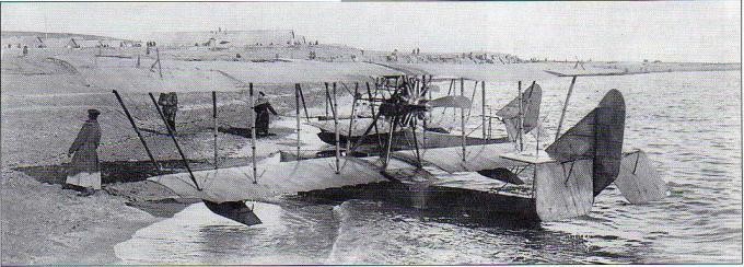
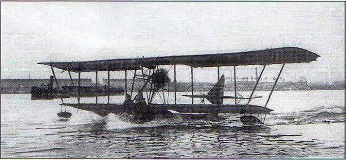
Mijaíl Maslov, researcher and historian and author of innumerable works in relation to the M-7 writes: The M-7, like the earlier M-6 appears to be an enlarged and unsuccessful version of the M-5 with a 150 hp Sunbeam engine. During the tests it failed to take off from the water. Modification attempts were of little help and eventually the aircraft was disassembled for spare parts. VB Shavrov however alleges that the M-7 featured modified contours, higher tread and a wide angle keel. The takeoff was heavy but in the air the model behaved normally.
AO Alexandrov agrees with Maslov that the M-7 was originally unflyable, but tells of possible later tests in Baku.
According to Alexandrov, the M-7 was a three-seat development model of the M-7 created in the PRTV in a period between July and August 1915. A document dated September 24 is preserved where it is detailed that in a few days this three-seater model would be tested.
Apparently the decision to build the M-7 was generated as the company’s own initiative with the aim of presenting a model that would compete with the Curtiss K.
For unclear reasons, which could be due to the lack of the right engine or the terrible autumn conditions, the tests did not begin until November. On the 4th the prototype was sent to Revel, but the trip to that city took about two weeks.
SS Shchetinin considered it essential to participate personally in the development of the tests, since he had a great interest in their results. Unfortunately, her hopes were dashed when the M-7 flying boat refused to take off from the water at the end of November. The company’s specialists kept hoping for an effective design and for this reason continued to work on the model. By mid-January 1916 the flying boat with a 150 hp Sunbeam linear V engine known as “Crusader”, was tested at the branch of the Petrograd Naval Pilot Officers School opened in Baku, on the shores of the Caspian Sea.
The results obtained with the new model M-9 led to the abandonment of attempts to continue working on the M-7. The subsequent fate is unknown.
M-7 Power plant: 1 Sunbeam 150 hp Propeller: 3 m diameter / 2.25 m pitch Accommodation: 3 Payload Capacity: 450kg Calculated top speed: 95km/h Calculated time to 2000 m: 30 min Calculated endurance: 5 – 5.5 hours
Vadim Borisovich Shavrov, aeronautical constructor, coworker of DP Grigorovich at OMOS and historian in his encyclopedic work “Aeronautical Construction in the USSR up to 1938” defines the M-6 (Russian: Григорович М-6) as a temporary version in the towards the M- 9:
M-6 with 150 hp Sunbeam engine. The hull of the flying boat was similar to that of the M-5 but with an enlarged keel. The forms were not very successful and the takeoff from the water was difficult.
Mijaíl Maslov, another prominent researcher and historian and author of innumerable works of recognized historical value, has not found clear evidence and in relation to the M-6 he writes:
Possibly this denomination was assigned to a new Grigorovich flying boat with a 150 hp Sunbeam engine that showed unsatisfactory results during the tests. In any case, to date no documents have been found that confirm the existence of a model with that name.
The aeronautical historian AO Alexandrov in his book “The airships of the Imperial Fleet 1894 – 1917 expresses, however, another theory that is still interesting:
There is evidence that SS Schetinin clandestinely built five copies of the Curtiss F model for the Black Sea Fleet, which were delivered between October and December 1915 at a unit cost of 5,595 rubles per unit.
According to Alexandrov, it could have happened that this adventure of creating the necessary flying boats without a license had led SS Schetinin to seriously think about the possibility of establishing an important production contract without development expenses and given the possibility that the M-5 model would not approved (especially since the Baltic Fleet rejected this flying boat in favor of the French FBA) to have an “Ace up the sleeve” in the form of a proven and successful design that could be presented to the Navy under the name public M-6 in order to avoid pretensions of the North American firm.
It is noteworthy that no Navy document mentions the M-6 model and the 5 copies of the Schetinin Curtiss F delivered to the Black Sea Fleet in the documents are only referenced with their registration number and sometimes with the letter “k” at the end.
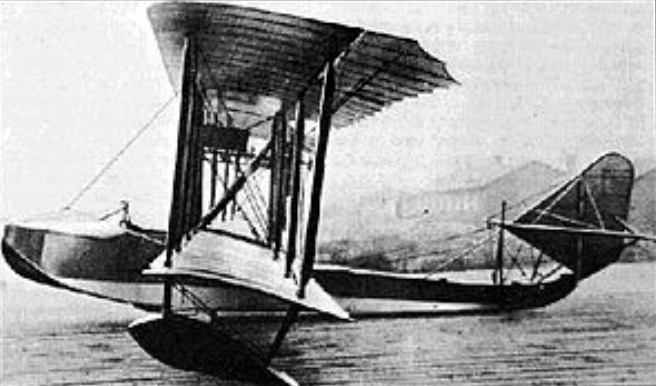
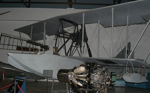
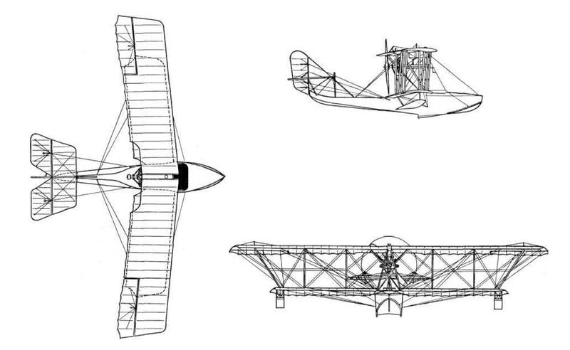
Grigorovich M-5 (alternative designation Shch M-5, sometimes also Shchetinin M-5 (Russian: Григорович М-5)) was a successful Russian World War I-era two-bay unequal-span biplane flying boat with a single step hull, designed by Grigorovich. It was the first mass production flying boat built in Russia.
During the summer and autumn of 1914 several flights were made on the M-2, proving that it still needed to work on the design in order to achieve a model capable of satisfying the needs of the Russian naval forces. The improvements introduced in the M-3 model did not bring the expected success either and this was understandable considering that the M-3 was just a version of the previous model with a more powerful engine and a new wing profile. The tests of this model did not show great differences in relation to the base model. Also unsuccessful was the later model M-4, a version with slight improvements to the hull design, new changes to the airfoil, and the same engine as the M-3.
It was produced, primarily to replace foreign built aircraft, including Curtiss Model K and FBA flying boats.
In his design Grigorovich used the information obtained from the French FBA models, which operated with the Baltic Fleet. On the way to obtaining the best possible design for the new model, Grigorovich decided to go to the Petrograd Polytechnic Institute, where one of the best aerodynamics laboratories in all of Europe existed, with a wind tunnel run by VA Sliesariev.
The M-5 was of a wooden construction, the hull was covered in plywood and the wings and tailplane were covered in fabric. Aft of the step the hull tapered sharply into little more than a boom, supporting a characteristic single fin and rudder tail unit, which was braced by means of struts and wires. It was normally powered by a 100 hp Gnome Monosoupape engine mounted as a pusher between the wings, but some used 110 hp Le Rhône or 130 hp Clerget engines. The pilot and the observer were accommodated side-by-side in a large cockpit forward of the wings, the observer provided with a single 7.62 mm Vickers machine gun on a pivoted mounting.
The M-5 was a development of the previous models with better hull hydrodynamics and modifications to the tail section for greater efficiency. Unlike earlier models, the wings were inserted into the sides of a deeper hull. The wingspan and surface of the lower plane were increased.
Grigorovich devoted great attention to strengthening the hull structure, especially in the areas that were in direct contact with the water. The railing was modified with a decrease in its height in the center to 70 mm and towards the sides of 140 mm. The sides of the bottom had some slats that allowed the flying boat to stay on the launching surface when leaving the water.
The structure was made of ash covered with 3 mm plywood on the edges and 5 – 6 mm on the bottom. 10 mm plywood was used in the recess area. The internal structure was made up of frames with diagonal reinforcement supports.
The assembly of the hull was done with brass screws with a lead or zinc coating. The joints in the hull skin were reinforced by plywood plates fixed with copper rivets from the inside. In the lower outer area of the hull, the joints were covered with 0.3 mm copper sheets and soldered together with tin. On the outside the wood coating was covered with varnish and on the inside with pitch. A special “marine” glue was also used during the assembly of the different pieces. It is interesting to note that all the work was manual. The hull had good rigidity, but even so breakages were common in aviation schools by inexperienced students.
The construction of the wings, the stabilizer and the keel of the vertical empennage was made of pine wood. The elevators and rudders were built from a light structure of thin-walled steel tubes (30×28 and 20×18 mm) with some wooden ribs and fabric covering.
The wing featured a double spar structure, built from I-profile pine pieces with holes to save weight. The wing ribs were made from 20 x 5 x 5 mm pieces of plywood, also lightened by perforations. Its wing profile was extremely thin (4% chord bristle). The interplanar supports were made of wood and the cross tensors were made of 5-8 mm cables. Cables were also laid between the wing box and the nose of the flying boat. The cables for the control surfaces were located on the outside of the flying boat, making them easy to service and repair.
The horizontal plane of the tail was raised to distance it from the effect of the water by means of a pyramidal structure of steel tubes and tension cables. This structure failed to ensure good rigidity and as a result the M-5’s tail twisted appreciably during turns and constantly vibrated. Despite this, an accident due to breakage of the tail unit was never recorded. The stabilizer was fixed to the tail bar and could be adjusted on the ground to change the angle of incidence. The bottom ski-paddle tested on the M-4 was eventually removed.
Most of the M-5s used the 100 hp Gnôme Monosoupape, which was installed in a steel tube structure fixed to the central supports of the wing box. This engine drove a 2.60 meter Shauviere propeller. Grigorovich constantly tried to improve the characteristics of the M-5 by using more powerful power plants (the 110-120 hp Le Rhône and the Clerguet were tested) of 130 hp, but when using these engines the performance worsened instead of improving, because as the weight increased, stability worsened and control became more difficult.
The manual ignition crank was located in the front region of the engine. The main fuel tank was located in the hull, behind the cockpit. The M-5 eliminated the tank from the upper plane. To get the fuel to the engine, a manual pump was used, which generated pressure in the tank, causing the fuel to rise constantly. The oil tank was originally located at the junction of the upper half-planes, but was soon enlarged to be located a little lower, at the junction of the central supports.
Pilot and observer were accommodated side by side in an open cabin, located immediately in front of the planes; In a few examples, the observer, located on the right, was in charge of handling a single machine gun mounted on a mobile mount. Additionally, the M-5 could carry an assortment of 8 kg bombs or two 50 kg bombs, directly in the cabin in the case of the small ones and hung in the case of the larger ones.
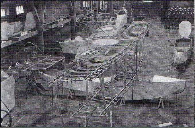
Assembly of M-5 at the Schetinin Factory
The first prototype M-5 was built at the Schetinin Factory in April 1915 and in May Ya. I. Siedov-Sierov carried out the tests on Kestovski Island. As early as April 16, S. S. Schetinin informed the Naval General Staff (MGSh) about the readiness of the factory to build four M-5 specimens at a cost of 9,500 rubles per unit, with deliveries from May 10 to 5 June. This proposal was accompanied by the promise to send, if necessary, all these planes and the assembly brigade made up of engineer, pilot and mechanic to Sevastopol to carry out the tests in which it was expected to reach a climb of 500 meters in 10 minutes. with a payload of 310 kg.
One of the first M-5s factory number 331 during the tests at the PRTV experimental station in July 1915.
In response to this proposal, a group of naval pilots visited the factory and on April 20, 1915, the commander of the port of Petrograd received the instruction to negotiate the contract, signed on May 27 for 12 copies to be delivered between May 30 and June 15. The closeness between the dates of signing the contract and the first delivery implies that the Schetinin Factory had several ready at that time.
Famous pilot George Friede, who flew on the M-5 under all the bridges on the Neva River, described the plane as outstanding. They possessed excellent seaworthiness, on tests exceeded some characteristics recorded in the technical specifications. For example, instead of the recorded 275 kilograms of cargo, it took 300 kg, the maximum height was gained not in ten minutes, but in three and a half.
The production company managed to fulfill the contract with only 5 days of delay in delivery. The reception was entrusted to Lieutenant GA Fride, an experienced pilot recognized as an aeronautical constructor.
M-5 number 331 showing the tail unit fixed by brackets and cables and the upper plane trailing edge fins.
Production of the series began in June 1915 and ran until mid-1917. By the time production was completed, some 200 examples had been delivered, of which the majority were built at the Schetinin Factory in Petrograd and another quantity at the Anatra factory in Odessa. After the October Revolution, production at Factory No.3 “Krasni Liotchik” in Petrograd was maintained until 1923, registering a total of about 300 copies.
M-5 contracts
Contract date: 27 May1915 Number: 12 Serial numbers: 316-327 9500 rubles per unit without motor Deliveries from May 30 to July 15
Contract date: 17 July 1915 Number: 10 Serial numbers: 331-340 Delivery for September 10, 1915
Contract date: 10 August 1915 Number: 3 Serial numbers: 328-330 Post-delivery contract. Delivered on July 20, 1915.
Contract date: 12 November 1915 Number: 16 Serial numbers: 440, 441, 537-542 10500 rubles per unit without motor Deliveries from November 1915 to March 1916.
Contract date: 21 December1915 Number: 10 Delivery of 10 frames without glue and motor. 4750 rubles per unit.
Contract date: 1 April1916 Number: 35 Serial numbers: 656-683, 687-690, 892,893, 895 Completed by September 23
Contract date: 16 June 1916 Number: 20 Serial numbers: 684-686, 894, 896-899,907-909, 993-995, 998, 999, 1001, 1018, 1020, 1021 10,500 rubles per unit without motor. Deliveries between July and August of that year.
Contract date: June 1916 Number: 20 Serial numbers: 904-906, 910, 996, 1000, 1002, 1019, 1022, 1023, 1028, 1030-1036 Contract intended for reserve, but later several entered service
Contract date: 2 September 1916 Number: 30 Serial numbers: 900-903, 911, 1024, 1025,1027, 1029, 1037-1045, 1047-1055. 1057 11,000 rubles per unit without motor Deliveries between October 1 and December 1, 1916
Contract date: 27 April 1917 Number: 70 11,000 rubles per unit without motor Deliveries between December 1, 1917 and April 1, 1918. Cancelled
Contract date: 29 April 1917 Number: 10 10 spare frames Completed for May 25, 1917
Contract date: 26 May 1917 Number: 25 Serial numbers: 1441-1460, 1461-1465 (possibly) 11,000 rubles per unit without motor Deliveries for July 20, 1917
Contract date: 28 July 1917 Number: 40 16,000 rubles per unit with a 125 hp Le Rhône engine Deliveries September 1, 1917 to January 1, 1918 Contract assigned to the new experimental factory Grigorovich
The M-5 was used primarily in the Black Sea and Caspian and in various flight schools, initially with the Imperial Russian naval air arm and later with both sides in the Russian Civil War. The low speed and the poor range did not allow it to stay for a long time in front-line tasks and by 1916 almost all went to the role of trainers. By 1917 the M-5 was already obsolete and did not meet to the requirements of the Navy. Some remained in service until the late 1920s as trainers, reconnaissance and utility aircraft.
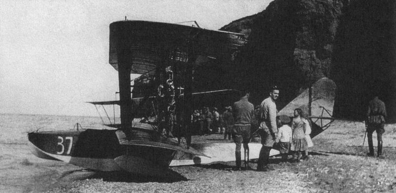
M-5 “37” Black Sea 1916.
The installed armament consisted of a Maxim, Vickers or Lewis machine gun installed on a bracket in front of the right-hand post usually with 450 rounds and an assortment of 8 kg or two 50 kg bombs. Small hand bombs could be carried in the cockpit and heavier ones could be hung under the wing. Starting in November, radio-telegraphy stations with a range of 40 km and Potte cameras (designed by Russian Army Sub-Colonel VF Potte) were installed on some. It was a 9-kg semi-automatic camera of weight with a lens of 21 cm of focal length and cassettes for 50 photos of 13 x 18 cm.)
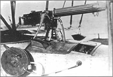
Maxim machine gun installed on an M-5 of the Black Sea Fleet.
In the Black Sea Fleet the M-5 model saw the most active use. By 1915 this force had outdated Curtiss F flying boats, which due to their performance and length of service were much inferior even to the Grigorovich M-4, of which two had been received. For this reason, the arrival of the first M-5 on May 16, 1915 was very well received. Soon this would generate an order for 12 serial copies. In total during the operational period of this flying boat in the Black Sea Fleet 71 were received.
In 1916 the naval pilots of the Black Sea receivef instruction called “Fight in the air” in which the combat methods of the M-5 were defined. The authors considered that the position of the machine gun on the M-5 guaranteed an excellent firing sector to the front, up and to the right. To the left it was only possible to cover about 60º. For this reason, M-5 crews were recommended to operate in pairs, with the second flying boat to the left and above the leader. At a distance of about 500 meters the first machine was to open fire in short salvos of 15-20 projectiles and upon reaching 100-150 meters begin continuous fire. In case the machine gun jammed, the crew had to use their Mauser pistols or Nagan revolvers.
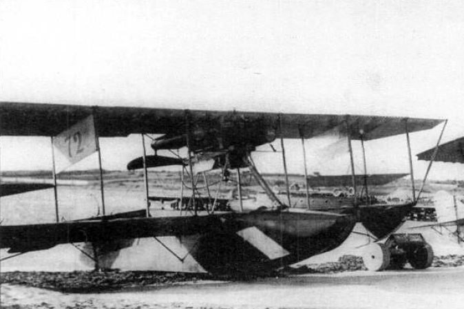
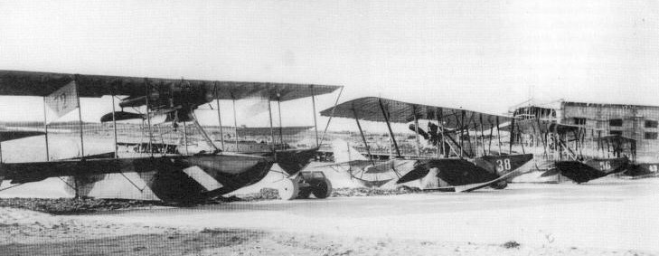
M-5 numbers 38, 56 and 43 next to Schetinin Curtiss F with number 72 at the naval station in the Kruglaya Bay in Sevastopol.
The aircraft of the Black Sea Fleet were based in Sevastopol, serving in the 1st and 2nd brigades of the air division, in Odessa and in Batumi. A certain amount was delivered to the 1, 2 and 3 air brigades on the cruisers “Alexandr I” and “Nikolai I” (capable of transporting 14 aircraft) and sometimes in the “Almaz” and “Pamyat Merkurya”. Aircraft of these cruisers participated in raids on the Turkish and Bulgarian borders. The most significant was the attack on the Turkish port of Zonguldak on January 24, 1916. This was carried out by the ship of the line “Empress María”, the cruiser “Kagul” and the cruisers “Alexandr I” and “Nikolai I”. 14 seaplanes were used, of which 11 managed to hit the target. The attack was carried out under heavy cloud conditions and return fire from the ground. Despite this, and due to the direct impact of a bomb, it was possible to sink the transport ship “Irminhard”, damaging several smaller ships and port facilities.
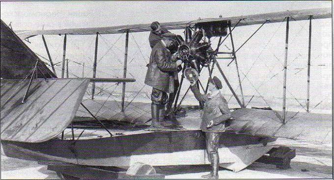
Repair of the Gnôme Monosoupape engine in an M-5
At the beginning of 1918 practically all the M-5 based in the Black Sea were in the zone occupied by the white troops or the Austrian interventionists. They continued to fly until 1919 – 1920.
On July 28, 1915, the Naval Aviation Officers’ School was opened in Petrograd. This center initially had four M-5 flying boats and two FBAs. Soon it was decided to open a branch of this school in Baku, on the Caspian Sea, which began operations on November 22, 1915.
Two flying boats of the Baku Flying School on the shores of the Caspian Sea.
The total number of M-5 flying boats used by the Petrograd school is unknown, but evidence has been found that in 1918, when the decision was made to evacuate the school to Nizhni-Novgorod after the start of the war with Germany, there were five in flight conditions, which were evacuated.
That same number existed at the Trotsky school, opened on November 1, 1918, on Gutuyevskaya Island in Petrograd. In the period from May to October 1919, the M-5s of this school participated in combat actions against the army of General Yudenish, who was advancing towards Petrograd.
M-5 navigating the Neva River in Petrograd.
In December 1919 the two former schools were unified into the Aviation Military Naval School, which was transferred to the Volga River near Samara. The school was installed on a barge called “Yevpraksya” specially equipped with hangars and systems for raising and lowering seaplanes into the water. Between 1920 and 1921 and basically using the M-5, 44 naval pilots were trained. In December 1921 this school was transferred to Sevastopol, where some M-5 were used until the mid-20s. By December 1925 in the Soviet naval aviation there were 22 M-5 and M-20 (version with different engine plant.)
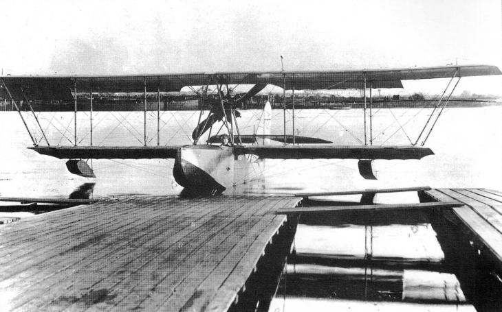
An M-5 flying boat launched in Baku in the winter of 1915.
Starting in 1917, the Baku branch became an independent training center equipped with excellent material conditions in terms of hangars, workshops and support systems for the operation of flying boats. Up to 20 M-5 were accumulated in this unit. Some of these flying boats participated in mid-1918 in the response to the Turkish offensive in the South Caucasus or Transcaucasia area. Active use resulted in most soon becoming unusable and by 1919 only two were still in flight condition. Due to the consequences of the Civil War, the school of naval pilots of Baku ceased to exist.
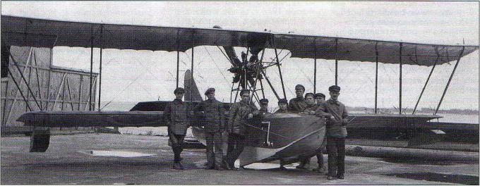
M-5 “7” Trotsky flight school on Gutuyevsky Island November 1918.
At least one M-5 flying boat was used in Finland after 1918 when it was found drifting at Kuokkala in 1918. This example was captured at Kuokkala in that year and remained in service with the Finnish Air Force until 1919, when it sank.
It is also known that at least one other fell into the hands of the Turks (possibly number 31 and delivered to the Black Sea Fleet on June 10, 1915), and is preserved to this day in the Hava Museci museum in Istanbul.
The M-5 was soon obsolete and was generally used as a training model. According to the evaluation of its pilots, the “Pyatak” (nickname assigned to the model and that could be translated as Little Fifth) was “pleasant” in flight, light and easily steerable. At sea it behaved well, being able to remain operational in rough seas with waves of 0.5 meters. The strong bottom allowed it to land directly on ice and snow and its excellent design made take-offs and landings easy.
On the other hand, its performance was not high. Flight speed was 100-105 km/h with a ceiling of only 3000 meters.
The M-5 basic production version was usually powered by a 100 hp Gnôme Monosoupape engine. Nearly 300 examples were produced at the Schetinin and Anatra factories before the Bolshevik triumph and later at Factory GAZ No.3 in Petrograd.
The 1916 М-10 version was characterized by maintaining the same Gnôme Monosoupape power plant and hull but with a reduced wing span which allowed the speed to be increased to 125 km/h. DP Grigorovich did not participate in the development of this version.
The М-20 1916 version was developed on the basis of the M-5 model with a new 120 hp Le Rhône power plant. A small series of 5 examples was built, characterized by a 40 cm shorter hull, which did not show great increases in performance.
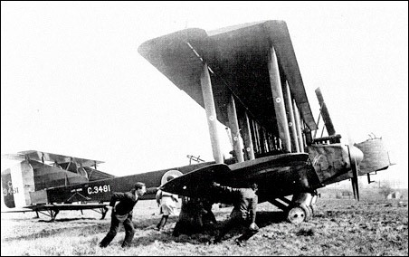
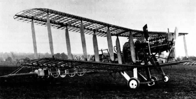
In 1918, the Grahame-White Aviation Company of Hendon, London developed a large, long-range heavy bomber intended to equip the Royal Air Force. The resulting design, the E.IV Ganymede, was a three-engined, twin-boom biplane with four-bay wings. Two of the engines were located at the front of the booms, driving tractor propellers, while the third engine was installed at the rear of the central nacelle, driving a pusher propeller.
A biplane tail unit with three fins and rudders spanned the gap between the two main fuselage booms. The two pilots and a bomb-aimer/gunner were accommodated in the central nacelle, while additional gunners cockpits were provided in each of the fuselage booms, with Scarff ring mountings for a machine gun together with a tunnel opening under the fuselages to allow the gunners to repel attacks from below.
It was intended that the Ganymede be powered by three 400 hp (298 kW) Liberty engine, but concerns about the availability of the American-built Liberty resulted in considerably less powerful Sunbeam Maori engines being specified when an order was placed for three prototypes. The first of these prototypes, serial number C3481 was completed late in 1918. While it was tested by the Air Ministry during 1919, the RAF had little interest in purchasing a new heavy bomber, and the remaining two prototypes were cancelled.
It is the first known type to carry the “E” letter used on all of Grahame-White’s latter models.
After being damaged in a landing accident in 1919, Grahame-White rebuilt the Ganymede into a civil airliner, becoming the E.9 Ganymede. The central engine was removed completely, while the two remaining engines were replaced by 450 hp (336 kW) Napier Lions. The nacelle was rebuilt with two pilots in an open cockpit ahead of a glazed cabin housing 12 passengers. The modified aircraft was granted a Certificate of Airworthiness on 12 September 1919, with the Aircraft registration G-EAMW, but was destroyed in a fire in September 1920.
E.4 Ganymede Engines: 3 × Sunbeam Maori, 270 hp (201 kW) each Wingspan: 89 ft 3 in (27.21 m) Wing area: 1,660 ft² (154.3 m²) Length: 49 ft 9 in (15.17 m) Height: 16 ft 0 in (4.88 m) Empty weight: 11,500 lb (5,227 kg) Loaded weight: 16,000 lb (7,273 kg) Wing loading: 9.64 lb/ft² (51.8 kg/m²) Maximum speed: 105 mph (91 knots, 169 km/h) at sea level Power/mass: 0.051 hp/lb (0.083 kW/kg) Endurance: 9 hours Guns: 3x .303 in (7.7 mm) Lewis guns, One in nose of central nacelle and one in each outer fuselage Crew: Five
The 1919 Grahame-White “Instructional” was an obscure twin-cockpit biplane trainer with dual controls and a Le Rhone engine. It was reportedly completed but there is no indication that it was flown
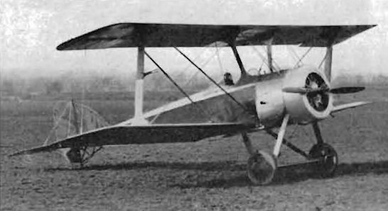
The 1917 Grahame-White Type 21 (G.W.21) was sometimes mistaken for the Type 20, despite considerable differences, this single-seat scout biplane was quite an improvement on the concept, with its unbalanced rudder, slab-sided fuselage, closer wings and the I-shaped interplane struts. It was powered by a rotary Le Rhone engine and tested with both two- and four-bladed propellers.
The Type 21 has been seen with the 80-h.p. Le Rhone driving a four-blade propeller.
Other similar aircraft by larger manufacturers were already in production and the G.W.21 remained a prototype.
The Grahame-White Type 20 (G.W.20) of 1916 was loosely based on a Morane-Saulnier configuration. This single-seat high-speed scout biplane presented an oddly large wing spacing. It remained a prototype.
Notwithstanding the work already in progress on the big Handley Page O/100 heavy bomber, the Admiralty issued a requirement in mid-1915 for a smaller, single-engine, land-based bomber, possessing a range of about 700 miles, capable of lifting 800 lb of bombs with a crew of two and a speed of 80 mph. Shorts had been quickest to produce a contender to this requirement, and accordingly received production orders. However, both Grahame-White and J Samuel White also produced prototypes, although none of the three aircraft tendered fully satisfied the performance demands.
Design of the big Grahame-White Type 18 (G.W.18) occupied much of the summer and autumn of 1915 and centred on the choice of a single 285hp Sunbeam Maori 12-cylinder water-cooled engine, the bearers being extensions of the upper fuselage longerons. The wooden box girder, which constituted the fuselage primary structure, carried formers to fair the fuselage to oval section. The three-bay wings were built up on twin spruce spars with closely-spaced ribs and four pairs of interplane struts, the inboard pairs (which replaced conventional centre section struts) providing the rigidity required for the wing-folding attachments.
The wings, of parallel chord and equal span, featured ailerons on upper and lower surfaces, and the twin mainwheel undercarriage with V-struts and spreader bar was augmented by a small balancing nosewheel. Bomb racks, capable of supporting two 230 lb or four 112 lb bombs were attached under the lower wings immediately outboard of the fold axis. A large fuel tank was located forward of the pilot’s cockpit, and the gunner/observer was evidently provided with a Lewis gun on what appears to be a ring mounting.
The Type 18 was probably completed in the spring or summer of 1916, by which time the Handley Page O/100 was confounding its critics by demonstrating the practicality of large bombing aeroplanes and, of the three bomber designs tendered, only the Short Bomber entered production, while the Wight Bomber was developed further by conversion into a floatplane, for which production orders were placed. By contrast, work was evidently halted on the Grahame-White Type 18 soon after completion, and no record of flight performance has been traced.
Little information has survived about this single-engined 1916 machine with a counter rotating construction of two four-bladed propellers. One was ordered as A8964 but later cancelled.
It could be that the designation Grahame-White M.1 originates from the contract (card) which may be held in the UK archives.
Pictured fully built, it was destined never to fly.