Junkers / Junkers-Fokker-Werke AG / Junkers Flugzeugwerke AG / Junkers Flugzeug und Motorenwerke AG

Professor Hugo Junkers (1859-1935) became enthusiastically interested in aircraft development and worked for several aero-engine manufacturers. Convinced that all metal structure was the ultimate answer to successful aircraft design, he produced the experimental J.1 “Blechesel” (Tin Donkey) to exemplify his 1910 patent for a cantilever all-metal wing. The J.1 flew on December 12, 1915, giving unexpectedly stable performance.

Hugo Junkers Article

Six J 2s were then built, but when J 4 ground-attack biplane was ordered for German Army, he was not geared for mass production. Thus, Junkers-Fokker-Werke was formed at Dessau on October 20,1917, with equal shares held by Junkers and Anthony Fokker. Conflicts of personality caused Fokker and Junkers to separate in 1918, and the Junkers re-formed following April as Junkers FlugzeugwerkeAG at Dessau April 24,1919, first concentrating on all-metal civilian transports such as F13 four-passenger monoplane (more than 350 built).

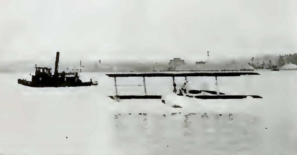
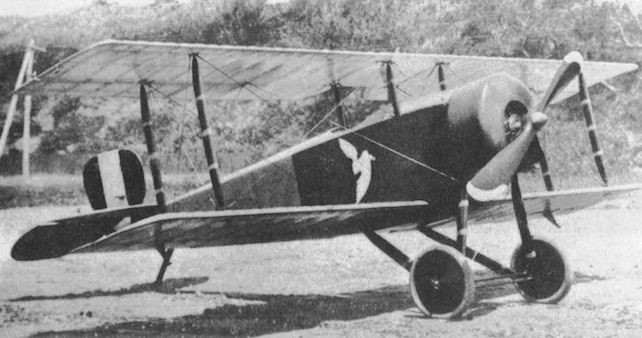
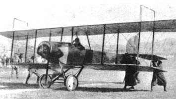
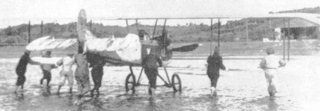
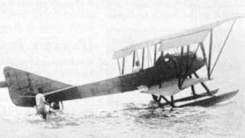
Representatives of the Junkers Flugzeugwerke (Jfa), the German Government (Reichswehrsministerium, RWM) and the Soviet Government (Trotsky) signed a final agreement on November 26, 1922, and a former motor car factory at Fili, situated south of Moscow, was taken over by Jfa and expanded. Back in the Dessau design office headed by Dipi Ing Emst Zindel, work had begun during 1922 on three new military types intended for production at Fili the J20 two seat low wing reconnaissance floatplane and the J21 two seat reconnaissance and J22 single seat fighter parasol wing aircraft. The parasol wing configuration of the two last mentioned types turned out to be a failure, even though the J21 was built in quantity at Fili.

Junkers established a Swedish subsidiary, AB Flygindustri, near Malmo, and formed Junkers Motorenbau GmbH for production of aero engines. After death of Hugo Junkers the company became state-owned and, amalgamating with the aeroengine firm, became Junkers Flugzeug und Motorenwerke AG in 1936, then the largest aviation company in the world. For German rearmament program, Junkers built factories in many other parts of Germany, and in Czechoslovakia and France.
Avions Metalicos Junkers was founded at Madrid in 1923 to provide facilities for the construction of Junkers aircraft in Spain. A two-seat all-metal monoplane was in production in 1924.

Major types produced included G24 and G31 airliners of 1925/1926: W33 and W34 cargo transports, used also as trainers by Luftwaffe; the G38 “flying wing”of 1928 (prototype flew November 6,1929; production models carried 34 passengers plus seven crew). Some used as military transports in early stages of Second World War. On October 13,1930 came the first flight of famous Ju 52 cargo transport. Three-engined Ju 52/3m based on latter used in wide variety of roles before and during Second World War, production totalling more than 4,850. Prewar production continued with Ju 60 and Ju 160 airliners, Ju 86 bomber, transport and trainer, and Ju 87 dive-bomber in many versions. The 87 was followed by the Ju 88/188/388 family of twin-engined bombers. The Ju 90/290/390 family began as four-engined 38/40-seat airliners, converted as heavy transport/reconnaissance types in Second World War. Junkers was among first companies to produce military jet aircraft. Two prototypes of its Ju 287 with forward swept wings were captured by Russians in 1945.

After Second World War aircraft production ended, Junkers joined with Messerschmitt in 1966, and with absorption of small aero-engine plant by Messerschmitt group in 1975, the Junkers name disappeared entirely.

Jeannin Stahltaube

The Jeannin Stahltaube (Steel Pidgeon) of 1914 is a late model of the typical light reconnaisance and training aircraft common at the start of WW I. Unarmed, heavy engine and barely maneuverable.

Length : 31.791 ft / 9.69 m
Height : 9.744 ft / 2.97 m
Wingspan : 45.505 ft / 13.87 m
Wing area : 387.504 sq.ft / 36.0 sq.m
Max take off weight : 1885.3 lb / 855.0 kg
Weight empty : 1323.0 lb / 600.0 kg
Max. weight carried : 562.3 lb / 255.0 kg
Max. speed : 62 kt / 115 km/h
Cruising speed : 54 kt / 100 km/h
Wing load : 4.92 lb/sq.ft / 24.0 kg/sq.m
Range : 162 nm / 300 km
Engine : Daimler D I od. Argus As I, 99 hp
Crew : 2

Jannus 1915 Flying Boat

A new and efficient design for rough water, ready assembly and disassembly, inherent stability, wide range of flying speed, waterproof construction of wings, enormous margin of safety, comfort for pilot and three passengers, and a dry, clean place for them to sit, this 1915 model is ideal.
The rough water ability is obtained in two principal ways: first, all the wing attachments are independent of the motor and propeller shaft; and. second, the low centre of gravity. Of special interest are the tapering end floats that never pound or jerk the wings. These taper from three inches wide across the bottom to a foot across the top. The taper has the advantage of reducing the planing surface, which at high speed would be sufficient to pound the wings badly, but when called upon as floats are quickly displacing water at an increased rate, easily combating the heaviest side lurching or listing or yawing tendency.
The removability of the tail for shipment has many advantages in construction and in simplicity of shipment for compactness. The motor remains in the front half of the hull with all controls intact. The control cables going to the tail and rudder all pass through individual leads in a conduit that is made of heavy steel as a protection against the propeller breaking or throwing anything with sufficient force to sever them.
Between the conduit and the controls the cables are supplied with the Jannus type sister hook, which locks the cables together in a permanent fashion quickly, and without additional safety wire or other auxiliary being necessary.
The wings are assembled in their entirety before being attached to the hull and, when on, cannot fail to align properly if reasonable care is taken. Where desirable they can he put on half at a time. To April 1915 the best record showed a total load of 2.200 lbs. carried in flight at 22-55 mph with an indicated 60 h.p.
Tests in the lee of large vessels, along windward shores and in other extreme conditions of gusty wind and treacherous obstacles prove that the new struts and the staggered planes are serious contenders for the inherent stability honors. The pilots reported that in no case was there any rapid inequality developed nor did the machine make any appreciable variation from its course due to these unfavourable conditions.
The tests have been conducted by Mr. Fritz G. Ericson and Mr. Antony Jannus.
The designers did not stagger the planes in this model for other than structural advantage.
The internal construction of the wing is free from ordinary glue and is amply strong without any adhesives, although liquid marine glue is used in all joints to maintain rigidity under severe stress and to prevent rotting. All bolts go on each side of the beams, through end grain blocks that are brass covered outside of the fabric.
The pilot is seated in front, leaving a seat behind for three large passengers. The ample foot space is well above the ribs of the bottom and made in the form of a grating that is removable for cleaning the bilge scuppers or any other purpose.
The motor compartment is segregated from all other parts of the boat, so that no oil or grease can be distributed.

Itoh Tsurubane No.2

In 1918, the japanese Army purchased from France some of the most highly regarded military aeroplanes of the First World War, among them Nieuport 24 fighter. This and others were evaluated at the newly established Kagamigahara Army Airfield. At that time, 27 October, 1918, Tomotari Inagaki, a long-time friend of the company, and still studying in Tokyo Polytechnical School, became engineer of Itoh Aeroplane Research Studio. By chance, he had an opportunity to visit Kagamigahara and was able to rationalize the design and manufacture of a small aerobatic aircraft similar to the designs he had just seen. Beginning on 8 January, 1919, Inagaki started his first design as a company employee. It was to be a single-seat single bay biplane, light in weight, rugged, and easy to fly.

Logically, the design followed that of the Nieuport, but to obtain sufficient lift with the low powered 50hp Gnome engine Inagaki increased the total wing area, yet retained the same overall wing span and chord of the upper wing, by enlarging the lower wing to conform to that of an equal-span biplane rather than the sesquiplane arrangement of the Nieuport. The appearance of this aeroplane was considered radical when compared to other Japanese aircraft at that time.

The front half of the fuselage was ply-covered. To enhance the aeroplane’s appearance and resemble a fighter aircraft after which it was patterned, Itoh himself painted a white crane like a unit insignia on the sides of the fuselage similar to those often used by the French Air Force. This aeroplane was completed on 21 April, 1919, and made its first flight on 25 April.

Although Yamagata began teaching himself the skills of aerobatic flying, much had to be learned from an English-language book he had bought. His efforts included being suspended upside down while strapped in a chair to visualize control movements while in inverted flight. On 5 May, using this aeroplane, he became the first civil pilot in Japan to complete a loop.

Engine: Gnome, 50hp
Propeller: two-blade wood
Span: 7.21m (23ft 8in)
Wing area: 14.58sq m (156.942sq ft)
Length: 5.77m (18ft 11.25in)
Height: 2.38m (7ft 9.5in)
Empty weight: 204kg (450Ib)
Loaded weight: 340kg (749Ib)
Maximum speed: 74kt (85mph)
Climb to 1,000m (3,280ft): 4min 30 sec

Itoh Tsurubane No.1

After the move caused by the destruction after the tsunami, ltoh Hikoki Kenkyusho built its first aircraft under the designation Tsurubane No.1 (“crane wing”). Its design was started by Ito’s assistant, The Tsurubane’s design was the result of the retrieval of a 50 hp (37 kW) Gnome rotary engine from the crashed Tamai No.3 by a relative of Itoh’s talented assistant, Toyotaro Yamagata, and given to him to create his own aircraft. This engine was purchased by Yamagata’s uncle to allow his nephew to finish the project. Yamagata made some initial sketches but Itoh was asked to take on the detailed design.

The aircraft that emerged was a wooden-structured, fabric covered two bay biplane. Its wings were rectangular in plan, with bays separated by pairs of upright, parallel interplane struts. The considerable overhang of the upper, greater span, wing was wire braced and a cabane of parallel struts held the central upper wing high above the fuselage. As on Itoh’s earlier aircraft there were ailerons only on the upper wings, with chords that increased outwards.

Its rotary engine was shrouded with a standard, open-bottomed cowling intended to collect oil spray. Behind it the fuselage became slender and flat-sided, as with Itoh’s earlier designs. Its pilot had an open cockpit near the wing trailing edge. The tail was like that of the Itoh Emi 2 with the horizontal tail mounted on the top of the fuselage carrying elevators that had a cut-out for rudder movement. The fin and rudder had upright, parallel edges but a sloping top.

Though its landing gear was a conventional, single axle design, Itoh was aware of the need to make it robust. It had large wheels and was taller than those of his earlier landplanes, with landing legs and rearward drag struts doubly cross-braced.

The Tsurubane was completed on 8 May 1918 and flown soon after.

The Tsurubane No.1, like several other early Japanese civil aircraft, initially paid its way with demonstration flights. Yamagata began with flights around Hiroshima. These attracted support from the Asahi Shimbun newspaper resulting in a tour of Korea, at that time part of the Japanese empire, throughout November 1918. In the following spring the Tsurubane gave many exhibition flights in Osaka. World-wide, early aircraft demonstrators included risky tricks to swell audiences: on one occasion the Tsurubane carried a passenger astride the fuselage.

When it was retired from demonstration flights, the Tsurubane was used as a trainer by Itoh’s flying school. It is not known how long it remained airworthy but it was eventually privately purchased, then donated to the Aki-Itsukushima Shrine near Hiroshima.

Tsurubane No.1
Powerplant: 1 × Gnome, 37 kW (50 hp)
Propeller: 2-bladed
Wingspan: 10 m (32 ft 10 in)
Wing area: 30 m2 (320 sq ft)
Length: 6.5 m (21 ft 4 in)
Height: 2.6 m (8 ft 6 in)
Empty weight: 380 kg (838 lb)
Gross weight: 520 kg (1,146 lb)
Maximum speed: 80 km/h (50 mph, 43 kn)
Cruise speed: 65 km/h
Crew: one

Itoh Emi 9

After the destruction of Itoh’s hangar at Inage Beach by a tidal wave at the end of September 1917 his works and flying school moved to Tsudanuma Beach, otherwise known as Itoh Airfield. The move led a significant increase in student numbers and a new, two seat trainer was needed; until then they had relied on single-seaters. The solution was provided not by Itoh or his employees but by a regular visitor to the airfield, Tomotari Inagaki. He designed a simple and stable two seat trainer around the water-cooled 80 hp (60 kW) Hall-Scott V-8 engine taken from the Emi 3. It became known as the Itoh Emi 9.

The Emi 9, typical of its time, had a wooden frame and fabric covering. It was a straightforward two bay biplane, with two parallel pairs of interplane struts on each side. The wings were rectangular in plan and manufacture was further simplified by the absence of dihedral or stagger.

Its upright V-8 engine was installed in the nose with most of the upper part exposed and its rectangular radiator mounted edge-on just behind the engine on the fuselage port side. Pupil and instructor had separate open cockpits in a fuselage rather similar to that of the Emi 5. Its tail was with a triangular fin, a rudder with a straight leading edge which continued that of the fin and a deep, rounded trailing edge, though the control surfaces had horn balances, the first to be used on a Japanese civil aircraft.

The Emi 9 had a simple, single axle undercarriage with legs on the lower fuselage longerons and trailing drag struts to the fuselage centre line.

Built in 1918 the Emi 9 served the Itoh school as intended, though details of its history are lacking.

Powerplant: 1 × Hall-Scott, 60 kW (80 hp)
Propeller: 2-bladed
Wingspan: 9.80 m (32 ft 2 in)
Length: 7.45 m (24 ft 5 in)
Height: 2.30 m (7 ft 7 in)
Empty weight: 350 kg (772 lb)
Maximum speed: 111 km/h (69 mph, 60 kn)
Crew: one instructor
Capacity: one student

Itoh Emi 3

Though by around 1916 demonstration flights by early Japanese aircraft were beginning to be commercially viable, there were no suitable seaplanes. Otojiiro Otoh, who had designed and built Japan’s second commercial landplane, the Itoh Emi 1, was encouraged to fill the gap. The result was the Emi 3, completed in August 1917.

Like most aircraft of its time, it was a wooden-framed and fabric covered biplane. It was a two-bay design with wings braced by two pairs of parallel, vertical interplane struts on each side but, as the upper wing had a significantly longer span, there was also pairs of parallel, outward- leaning struts to brace the overhang. Only the upper wings carried ailerons.

Its water-cooled 80 hp (60 kW) Hall-Scott V-8 engine drove a two-bladed propeller. Close behind it there was an open cockpit for one passenger; the pilot’s cockpit was just aft of the upper wing trailing edge. The Emi 3’s fuselage was flat-sided and quite slender, with the horizontal tail mounted on its top. Its fin had a triangular profile and carried a rudder of roughly parallelogram profile.

It had twin floats, mounted with a pair of single struts to the fuselage forward and a transverse W-form strut to the fuselage and lower wing aft.

The Emi 3 was built at Itoh’s Inage Beach site and, assisted by Toyokichi Daiguchi and Toyotaro Yamagata, and with the help of student pilots, the aeroplane was completed in August 1917. Flight tests by several pilots found its performance, stability and handling were good.

Test flights over, the Emi 3 was taken by rail to Osaka. In preparation for demonstration flights, the Emi 3 Seaplane was assembled and maintained in a hangar located on the beach at Nishinomiya, just west of Osaka. Spectators’ fees made these flights a commercial success for Japan’s first passenger-carrying floatplane. Itoh named the only example Seagull (Kamome, かもめ).

Powerplant: 1 × Hall-Scott water-cooled V8, 60 kW (80 hp)
Propeller: 2-bladed wooden
Upper wingspan: 15.41 m (50 ft 7 in)
Wing area: 46.5 sq m (501 sq ft)
Length: 7.27 m (23 ft 10 in)
Height: 4.51 m (14 ft 10 in)
Empty weight: 580 kg (1,279 lb)
Maximum speed: 43kt (50mph)
Crew: one
Capacity: one passenger

Itoh Emi 2

Itoh Emi 2

By early 1917 Itoh had begun the design of a new aircraft. The Emi 2 owed much to its predecessor, both biplanes with wooden structures and fabric covering. Rectangular plan wings, shorter in span by 2.50 m (8.2 ft) and using a lower drag profile than before, were braced with pairs of parallel interplane struts, though the Emi 2, a two-bay biplane, had one less bay on each side. The Emi 2’s upper wing had a slightly greater span than the lower one, which had more rounded tips. The centre of the upper wing was supported over the fuselage by four parallel cabane struts. As on the Emi 1 there were ailerons, with chords which increased outwards, only on the upper wings.

The Emi 2 also inherited its predecessor’s engine, the 26–34 kW (35–46 hp) Grégoire Gyp. The flat-side fuselage had an open cockpit for the pilot; a semi-circular cut-out in the upper trailing edge increased the pilot’s upward field of view. The long span horizontal tail was roughly rectangular in plan and mounted on the upper fuselage and the vertical tail also was also parallel-sided, though with a sloping top.

The Emi 2’s wide track landing gear had two, rather than four wheels, each on a landing leg with bungee cord shock absorbers.

It flew for the first time in April 1917.

From May 1917 Itoh gave a series of demonstration flights from his east Inage Beach base, culminating in a visit to his home town of Osaka in September. His timing was fortunate, as his Inage Beach hangar was flattened by a typhoon-related tidal wave at the end of the month, while t Emi 2he was away. Demonstration flights resumed until the Emi 2 began use as a trainer from Itoh’s new base at Tsudanuma Beach.

Its last operations were under new owners based near Hammamatsu. It was again used for demonstration flights, piloted by the inexperienced Asao Fikunaga aound Osaka from August 1919. One flight took him to his home town of Toyonaka but the Emi 2 overturned on landing and was badly damaged. It was rapidly repaired but in May 1920, leaving Osaka, the aircraft hit a house roof, ending its career.

Powerplant: 1 × Grégoire Gyp, 26–34 kW (35–45 hp)
Propeller: 2-bladed
Maximum speed: 85 km/h (53 mph, 46 kn)
Wingspan: 9 m (29 ft 6 in)
Wing area: 25 m2 (270 sq ft)
Height: 2.25 m (7 ft 5 in)
Empty weight: 250 kg (551 lb)
Crew: one

Itoh Emi 1

By early 1915 Otijiro Itoh had established the Itoh Aeroplane Research Studio and an associated flying school and by that autumn had completed his first design, the Emi 1. The “Emi” was a respectful nod to the district of Osaka where he grew up.

The sole Emi 1 was a three-bay biplane with a fabric covered wooden structure. Its wings were of equal span and joined by parallel pairs of interplane struts. The upper wing was well above the fuselage and the lower ones mounted on the lower fuselage longerons. The Hyabusa-go’s French, 35–45 hp (26–34 kW) Grégoire Gyp four cylinder, water-cooled inline engine powered it. Its pilot had an open cockpit. At a time when there were few prepared airstrips, landing gear needed to be robust and the Emi 1’s gear had two wheels on each leg.

Its first flight was on 11 November 1915.

On 8 January 1916, not long after the first flight, Itoh flew the Emi 1 from his base at Inage Bay to Tokyo. This took 55 minutes and was the first flight to Tokyo. He later flew it to 58 Japanese cities, partly to advertise his aircraft and partly to raise air-mindedness in Japan. The Emi 1 was the second successful Japanese aircraft, following the Narahara 4 ”Ohtori-go”.

Later the Emi 1 was re-engined at Inage Bay with a 50 hp (37 kW) Hino Type, remaining in use with the flying school.

Emi 1
Powerplant: 1 × Grégoire Gyp 26–34 kW (35–45 hp)
Propeller: 2-bladed fixed-pitch
Wingspan: 11.50 m (37 ft 9 in)
Wing area: 33 m2 (360 sq ft)
Length: 6.65 m (21 ft 10 in)
Height: 2.50 m (8 ft 2 in)
Empty weight: 350 kg (772 lb)
Maximum speed: 76 km/h (47 mph, 41 kn)
Crew: one