Mercedes D.III / F1466

Mercedes D.IIIa

The Mercedes D.III, or F1466 as it was known internally, was a six-cylinder, liquid cooled inline aircraft engine, first run in 1914, built by Daimler and used on a wide variety of German aircraft during World War I. The initial versions were introduced in 1914 at 160 hp, but a series of changes improved this to 170 hp in 1917, and 180 by mid 1918. These later models were used on almost all late-war German fighters, and its only real competition, the BMW III, was available only in very limited numbers.

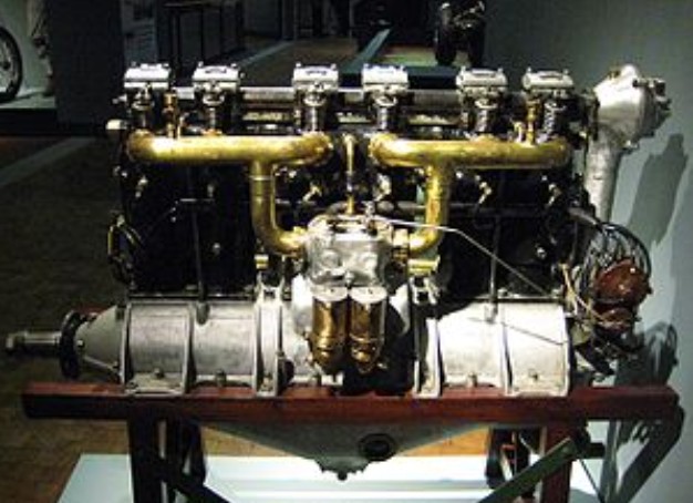
The D.III was based on the same pattern as the earlier Mercedes D.II, suitably scaled up for higher power settings. Like most inlines of the era, it used a large aluminum crankcase as the main structural component, with separate cylinders made from steel bolted onto it. The technology for screwing a threaded cylinder of steel into an aluminum crankcase did not exist at that time. Jackets for cooling water covered the top 2/3 of the cylinder, feeding a radiator via connections at the back of the engine.
The D.III featured a rather prominent overhead cam operating the single intake and exhaust valves, powered by a shaft running up from the crankshaft at the rear of the engine. Ignition was provided by two sets of spark plugs, one located on either side of the cylinders, each powered by a separate magneto for redundancy. The ignition cables were protected in tubes running down either side of the cylinders. Fuel was fed into the cylinders via pipes on the left side of the engine as viewed from the rear, supplied from a twin-barrel carburetor located just above the crankcase. Both the fuel and oil reservoirs were pressurized by an air pump run off the crank.

The only obvious design change from the earlier D.II was to use separate cooling jackets for each cylinder, whereas the D.II used one jacket for every two cylinders. Daimler also used the pistons of the D.III to produce the reduction geared, eight-cylinder 220 hp Mercedes D.IV during this period, but it did not see widespread use.

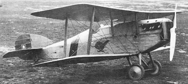
The original D.III was introduced in 1914. While it saw widespread use in early examples of the C-series of two-seat general-purpose biplanes the D.III did not see use in fighters until 1916 when the fighters grew to need that level of power; earlier designs were generally powered by lighter rotary engines of about 110 hp or by water cooled inline engines in the 100 to 120hp range such as the earlier Mercedes D.II. By 1917 the D.III was being widely used in fighters, most notably on the famous Albatros D.I. Production of this version was essentially wound down by May 1917, with only a handful continuing to be delivered until October. British hp ratings being slightly different to the German PS or (Pferd Starke) standard, it is probable that this engine would have had a slightly higher rating under British HP numbers.

Development of the basic design led to the slightly modified 170 hp D.IIIa, which took over on the production lines in June 1917. The main change was to change the piston profile to have a flat head instead of the former concave one, thereby slightly increasing maximum compression. Other changes were mainly in design details, notably a redesigned crankcase and new carburetor. Many of the accessories were also redesigned or moved around on the engine. This model was produced only briefly, for use on the Albatros D.III but there are indications that possibly some early Albatros (Alb.) made Fokker D.VII’s were also equipped but probably had the engines upgraded or replaced as quickly as possible. This engine has been referred to in postwar British analysis as generating 180 hp.
A more “radical” upgrade was the 180/200 hp D.IIIaü, introduced in late 1917, the D.IIIaü was a standardized refinement of the D.III and D.IIIa design and the ü designation was never official. This engine changed the pistons again, this time to a domed profile that further increased the maximum compression – the ü was for “über”, meaning “overcompressed”. Additionally, a new altitude-compensating carburetor was added, which improved performance at higher altitudes. To support operations at these altitudes, water from the radiator was used to heat the air intake and prevent icing in the carburetor. The aü model, which included upgraded D.III and D.IIIa engine blocks, was the most prolific German fighter engine of 1918 and designed into most fighter designs from late 1917 on. This included most of the entries in the First Fighter Competition at Adlershof in January 1918, notably the Fokker D.VII. In British post war evaluation the D.IIIaü demonstrated 200 hp according to the British standards.

A final version attempting to keep the D.III block competitive was the 200 hp (200-217 hp) D.IIIav (or avü), introduced mid-October 1918. The av used slightly longer pistons made of aluminum (possibly a first for a production engine), increasing the compression yet again, while at the same time allowing them to move faster due to the reduced weight. The maximum allowable RPM increased from 1,400 in the earlier models to 1,600 in the av, accounting for most of the gains in power. It is unclear if any av’s saw service use. The increased use of Benzol in German aviation fuel may have helped this final upgrade of power, it’s higher octane rating being better suited for the higher compression ratio.

All of the D.III series were generally very similar to other models, with the exception of the piston profile and carburetor details. It appears that upgrades were available for many of the engines, certainly for the III to IIIa, and IIIa to IIIaü. It would seem unlikely that early III’s would ever make it to the IIIaü standard, as they would almost certainly have been worn out in service before then. A more obvious change concerned the layout of the rocker arms that operated the valves. Early models had square cases positioned directly over the cylinders with the rocker arms exiting through vertical slots cut into the sides of the boxes. In later versions of the engines, the boxes were moved rearward and the cylindrical rocker arm shafts protruded forwards through the front surfaces of the boxes, operating the now fully exposed rocker arms with the exposed shaft ends. The newer arrangement can be seen in the image above (compare with the image of the D.II) and were stated as being interchangeable as a set with the complete camshaft, rocker boxes, rocker arms and valve springs, with the D.III’s earlier cam drive system design.

Confusingly, the “ü” was not an official part of the name. This leads to a number of problems in various references, which often confuse the IIIa with the IIIaü, listing the former as a 180 hp engine. It should also be noted that there are two D.IV engines, one the eight-cylinder based on the D.III pistons, and the later six-cylinder D.IVa which was essentially unrelated.

The D.III line of engines would find themselves eclipsed in performance by the BMW IIIa of 185 and then 200 hp (British rated it at 230HP) in 1918, however, the small number of BMW’s produced ensured that the Mercedes D.III series would be the primary German fighter engine up to the last month or two of the war and it would still be seen in very large numbers even at the end. At the end of the war the D.IIIaü would still be the numerically predominant German fighter engine. As a result the Fokker D.VII’s (those not equipped with BMW IIIa’s) and the Pfalz D.XII’s would be engine limited in performance (as opposed to “airframe-limited”) and yet would still be formidable adversaries to their Allied counterparts. The D.IIIaü was considered the optimum engine for the Roland D.VI, Pfalz D.IIIa, and Albatros D.Va fighters whose airframes were of an earlier, “all-wood” generation in design.

Variants:

Mercedes F1466
Company designation for the D.III

D.III
The original producction version directly developed from the Mercedes D.II developing 150 – 160 hp

D.IIIa
An up-graded D.III introduced in 1917 rated at 170 hp

D.IIIaü
An unofficial designation, (ü for über), for D.IIIa engines with domed pistons, operating “over-compressed”, (at a higher compression ratio). These engines were not able to operate at full throttle at sea level, utilising a self compensating carburettor. 180/200 hp

D.IIIav
D.IIIa engines with the domed pistons made from Aluminium alloy giving the higher compression ratio as well as a higher operating rpm and thus more power. 200 hp (200-217 hp)

D.IIIavü
alternative unofficial designation for the D.IIIav

Applications:
AEG C.IV
AGO C.I
Albatros C.I
Albatros C.III
Albatros C.XIII
Albatros D.II
Albatros D.III
Albatros D.V/D.Va
Albatros W.4
Daimler L11
Daimler L14
Fokker D.IV
Fokker D.VII
Halberstadt CL.II
Halberstadt CL.IV
Hansa-Brandenburg C.I Series 63
Hansa-Brandenburg W.12
Junkers CL.I
LFG Roland C.II
LFG Roland D.II
LFG Roland D.VI
Rumpler C.I
Rumpler 6B
Pfalz D.III
Pfalz D.XII
R-Planes

Specifications:

D.IIIaü
Type: 6-cyl. water-cooled in-line piston engine
Bore: 140 mm (5.51 in)
Stroke: 160 mm (6.30 in)
Displacement: 14.8 l (903.15 cu in)
Length: 1,650 mm (64.96 in)
Width: 490 mm (19.29 in)
Height: 1,070 mm (42.13 in)
Dry weight: 310 kg (683 lb)
Valvetrain: DOHC rocker operated single inlet and exhaust valves.
Fuel system: Dual Mercedes twin-jet carburettors
Fuel type: Gasoline
Oil system: Pressure system; multiple plunger pump
Cooling system: Water-cooled
Power output: 129.75 kW (174 hp) at 1,400 rpm (rated power at sea level), 152.12 kW (204 hp) at 1,600 rpm (maximum power at altitude)
Specific power: 0.2259 hp/cu in (10.281 kW/l)
Compression ratio: 4.64:1
Specific fuel consumption: 0.412 l/kW/hour (0.541 pt/hp/hour)
Oil consumption: 0.027/kW/hour (0.0355pt/hp/hour)
Power-to-weight ratio: 0.492 kW/kg (0.299 hp/lb)
BMEP: 0.75 MPa (109.1 psi)

Mercedes D.II / Daimler D II

Daimler D II

The Mercedes D.II was a six-cylinder, liquid cooled inline aircraft engine built by Daimler during the early stages of World War I. Producing about 110 to 120 hp, it was at the low-end of the power range of contemporary engines, and was generally outperformed by rotaries whose power-to-weight ratio tended to be much better. It also had stiff competition from the Ferdinand Porsche-designed 120 hp Austro-Daimler 6. The D.II was produced only briefly as a result, but its design formed the basis for the later Mercedes D.III which saw widespread use throughout the war.

The D.II was based on the Austro-Daimler to a large degree. Like the Austro-Daimler, it was built up from the crankcase, which was milled from two pieces of cast aluminum bolted together at their midline. The cylinders were separately milled from steel and bolted to the top of the crankcase. Steel sleeves were fitted over the cylinders and welded on to form a cooling jacket. Much of this complexity is due to the differential rates of expansion of steel and aluminum, which precluded screwing the cylinders into the crankcase, and the alloys of the era meant that an aluminum cylinder was not possible. Both engines also used a scavenger pump to pump oil out of the crankcase to a separate cylinder, where a second high-pressure pump supplied oil to the engine. This arrangement allowed for a much smaller “sump” on the bottom of the crankcase, reducing the overall size of the engine, although in the case of the D.II it was not nearly as much as the Austro-Daimler.

Where the D.II differed from the Austro-Daimler was largely in mechanical arrangement. For instance, the D.II featured a single overhead cam, powered by a shaft leading up from the crankshaft at the rear of the engine, whereas the Austro-Daimler had a more conventional valvetrain using pushrods driven from the crankcase. Another unique feature was the ability to shift the camshaft to a half-compression position for starting. The D.II used two carburetors located together on one side of the engine, feeding the cylinders through two manifolds; the Austro-Daimler separated its carburetors to locate them closer to the cylinders they fed. The D.II also used a unique cooling jacket design, with every two cylinders being covered by a single jacket.

The D.II was fairly quickly replaced by the D.III, and ended production around 1916. The D.III was essentially a scaled-up D.II, although it abandoned the paired cooling jackets.

Applications:
Aviatik B.II
Aviatik C.I
Albatros B.I
Albatros B.II
DFW B.II
Fokker D.I
Friedrichshafen FF.29
Halberstadt D.II
Junkers J 1 Blechesel
Zmaj Fizir FN

Specifications:

D.II
Type: 6-cylinder, inline piston engine
Displacement: 579 cu in
Dry weight: 449 lb
Reduction gear: Direct drive, left-hand tractor
Power output: 120 hp at 1,400 rpm

Mercedes D.I

The Mercedes D.I was a six-cylinder, water-cooled, inline engine developed in Germany for use in aircraft in 1913. Developing 75 kW (100 hp), it powered many German military aircraft during the very early part of World War I.

Applications:
AEG B.I
AEG G.I
Albatros B.I
Albatros G.I
Aviatik B.I
DFW B.I
DFW Floh
Fokker D.I

Specifications:

D.I
Type: 6-cylinder, inline piston engine
Reduction gear: Direct drive, left-hand tractor
Power output: 75 kW (100 hp)

Maybach HS / Mb.IV

The Maybach Mb.IV, originally designated Maybach HS, (only related to the Mb IVa by layout and size), was a six cylinder in-line, water cooled, piston engine, originally developed for use in airships, it was also used for large aircraft such as the Dornier Rs.I giant seaplane. Variants of the original HS engine included the Maybach HS D and Maybach HS Lu

MbIVa’s featured six over-sized cylinders, a compression ratio of 6.7/1 and a dry weight of about 860lb. (in the 1918 version with aluminum pistons.) There was a floatless carburetor at each end of the engine (working with a ball-and-sump setup) and the engine was hand-cranked, with compression reliefs on the cylinders magneto starting and hand-powered suction primer. Designed for high-altitude flying, they could not be run a full throttle below 6000 feet. Rugged, reliable power plants, they could run out about 2000 hours between overhaul.

Variants:
Maybach HS
Company designation

Maybach HS D
A variant of the HS

Maybach HS Lu
A high compression high altitude rated variant.
Power: 240-hp

Mb.IV
The Idflieg designation for production HS engines.

Applications:
Dornier Rs.I
LVG G.III
Siemens-Schuckert L.I

Maryland Pressed Steel Company

In 1917 the Maryland Pressed Steel Company of Hagerstown, MD hired Bellanca as a consulting engineer.
The aircraft department of Maryland Pressed Steel Company at Hagerstown, Maryland, built designs of Joseph Bellanca, who in 1919 developed single-seat CD biplane powered by 35 hp Anzani engine, and the CE two-seat biplane. With the conclusion of WWI, Maryland Pressed Steel’s contracts were cancelled and the company entered into receivership. Thus, the CE never went into production. Activity ceased and Bellanca joined Omaha Aircraft Corporation in Autumn 1921.

Martin & Handasyde F.4 Buzzard

The Buzzard began life as a private venture design by G H Handasyde designated F.3. The, F.3 was powered by the 275hp Falcon III engine, but priorities in Falcon engine supplies enjoyed by the Bristol Fighter led to the reworking of the F.3 for the 300hp Hispano-Suiza 8Fb. With this it was redesignated F.4 and (from September 1918) officially named Buzzard. It is uncertain just how many of the original batch of 150 aircraft were completed as Falcon-engined F.3s, but most were certainly finished as HS 8Fb-engined F.4s, the first of the latter being tested at Martlesham Heath in June 1918.

Additional contracts for the F.4 were placed with the parent company (300), Boulton & Paul (500), Hooper (200) and Standard Motor (300). Armed with two synchronised 7.7mm Vickers guns, the F.4 differed from the F.3, apart from power plant, in having revised fuselage decking contours and more extensive plywood skinning. Belated engine deliveries and other factors delayed production, only seven having been handed over by November 1918, and, in the event, no RAF squadron was to be equipped with the type.

Contracts for some 2500 were cancelled after the Armistice, including 1500 which were to have been built in the US.

Production of the F.4 by the parent company continued for a time after the Armistice (no other contractor apparently producing any complete Buzzards) and more than 370 airframes were built, some being fitted with Falcon engines. A number of F.4 Buzzards was sold abroad by the Aircraft Disposal Company, the principal recipients being Finland (15), Portugal (4), Spain (20) and the USSR, the last-mentioned procuring 100 aircraft of this type. One 290-hp M-6 eight-cylinder water-cooled engine in Russian-built F.4s. One F.4, along with an S.E.5A, were supplied to the Imperial Japanese Navy in 1921 22 as examples of single seat fighters with stationary engines.

A two-seat variant, the F.4A, was produced in 1920, a much-modified derivative with two-bay wings of increased span appearing in the following year. This had a Lewis gun in the rear cockpit and several were supplied to Spain in June 1921, both single- and two-seat Buzzards being referred to as F.4As in Spanish service.

The Aircraft Disposal Company developed the F.4 into the less successful ADC 1.

Bruce Murdin
Email: murdin@btinternet.com
I have an original 1919 propeller from an F4 Buzzard that was owned by my father for the last 50+ years. If anyone is interested in buyimg it, please contact me on the above email address
March 2016

Engine: 300hp Hispano-Suiza 8Fb
Prop: Lang L.P.5270A or 5270B two-blade wooden, diameter 2690 mm (8 ft 9.9 in), pitch 2000 mm (6 ft 6.7 in), or Lang L.P.5420 two-blade wooden airscrew, diameter 2660mm (8 ft 8.7 in), pitch 1 980mm (6 ft 5.95 in); Wing span, upper, 32 ft 9.4 in (10,99 m), lower, 31 ft 2.4 in (10,51 m)
Length: 7.76 m / 25 ft 6 in
Height: 2.69 m / 8 ft 10 in
Wing area: 29.73 sq.m / 320.01 sq ft
Loaded weight: 2,398 lb (1 088 kg)
Empty weight: 821 kg / 1810 lb
Normal fuel capacity, (Buzzard Mk I, Hispano¬Suiza): petrol, 38 Imp gal (172,71); oil, 4 gal (18,21) later 75 gal (341); water 9 gal (40,91). Buzzard Mk Ia: petrol 56 gal (254,61), oil 75 gal (341).
Max speed, 132mph (212 km/h) at 15,000 ft (4 570 m)
Time to 10,000 ft (3 050 m), 7.9 min
Armament: Two fixed 0303-in (7,7-mm) Vickers Mark 1* machine-guns synchronized by Constantinesco C.C. Gear Type B with (ultimately) 770 rpg; 1 8-in (45,72-mm) Aldis optical sight and 5-in (127-mm) ring-and-bead sight.

Martinsyde F.4 Buzzard

Martin & Handasyde F.3 Buzzard

The Buzzard began life as a private venture design by G H Handasyde designated F.3. A single-bay staggered biplane of conventional wooden con¬struction with fabric skinning and powered by a Rolls-Royce Falcon engine of 285 hp.

The F.3 appeared in the autumn of 1917 and underwent its first official trials on 3 October, six further prototypes being ordered and a decision to manufac¬ture the F.3 in quantity being taken before the end of 1917.

The F.3 was powered by the 275 hp Falcon III engine, but priorities enjoyed by the Bristol Fighter in Falcon engine supplies led to the reworking of the fighter for the 300 hp Hispano-Suiza 8Fb with which it was redesignated F.4 and (from September 1918) officially named Buzzard. It is uncertain as to how many of the original batch of 150 aircraft were completed as Falcon-engined F.3s, but the bulk was certainly finished as HS 8Fb-engined F.4s.

An installation for the 240-hp Lorraine 8Bb eight-cylinder water-cooled engine was designed and may have been made.

On the F.3 the armament could be supplemented by one 0303-in (7,7-mm) Lewis machine-gun mounted on the rear spar of the centre section. The first Buzzard Mk 1a, H6540, at one time had two supplementary Lewis guns partly let into the upper surface of the lower mainplanes, one on each side.

Engine: One 285-hp Rolls-Royce Falcon experimental
Prop: Lang L.P.3770A two-blade wooden airscrew, diameter 2850 mm (9 ft 42 in), pitch 3 050 mm (10 ft)
Normal fuel capacity: petrol 32 Imp gal (145,5 lt), oil 3 gal (13,6 lt), water 6 gal (27,3 lt)
Span, upper, 32 ft l0in (11,0 m), lower 31 ft 6 in (10,6 m)
Length, 25 ft 8 in (7,8 m)
Height, 8 ft 8 in (2,85 m)
Wing area, 337 sq ft (31,34 sq.m)
Armament: Two fixed 0303-in (7,7-mm) Vickers Mark 1* machine-guns synchronized by Constantinesco C.C. Gear Type B with (ultimately) 770 rpg; 1 8-in (45,72-mm) Aldis optical sight and 5-in (127-mm) ring-and-bead sight.

Engine: one 275-hp Rolls-Royce Falcon III 12-cylinder water-cooled
Prop: Lang L.P.3770A two-blade wooden airscrew, diameter 2850 mm (9 ft 42 in), pitch 3 050 mm (10 ft)
Normal fuel capacity: (B1490), petrol 39 Imp gal (177,31), oil 435 gal (19,81)
Span, upper, 32 ft l0in (11,0 m), lower 31 ft 6 in (10,6 m)
Length 25 ft 6 in (7,8 m)
Height, 8 ft 8 in (2,85 m)
Wing area, 337 sq ft (31,34 sq.m)
Armament: Two fixed 0303-in (7,7-mm) Vickers Mark 1* machine-guns synchronized by Constantinesco C.C. Gear Type B with (ultimately) 770 rpg; 1 8-in (45,72-mm) Aldis optical sight and 5-in (127-mm) ring-and-bead sight.

Martin & Handasyde F.2

Of more modern concept that the F.1, the F.2 two-seat fighter was, like its predecessors, of wooden construction with fabric skinning, apart from the sides and top decking of the fuselage which were plywood covered.

Designed and built while the F.1 was under construction, the F.2 underwent official testing two months prior to its predecessor, in May 1917. The F.2 was powered by a 200hp Hispano-Suiza 8Bd eight-cylinder water-cooled engine and carried an armament of one fixed and synchronised 7.7mm Vickers gun and one Lewis gun on a Scarff ring. Shortcomings revealed during official trials ruled out a production order, and the prototype was utilised as a test-bed for the then-new Sunbeam Arab engine.

Max speed, 120 mph (193 km/h) at sea level
Time to 10,000 ft (3 050 m), 13.5 min
Endurance, 2.5 hrs
Empty weight, 1,547 lb (702 kg)
Loaded weight, 2,355 lb (1 068 kg)
Span, 32 ft 0 in (9,75 m)
Length, 25 ft 0 in (7,62 m)
Height, 8 ft 2 in (2,49 m)
Wing area, 334 sq ft (31,03 sq.m)