Slingsby T.49 Capstan

Slingsby T49B Capstan

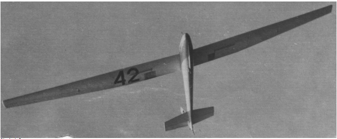
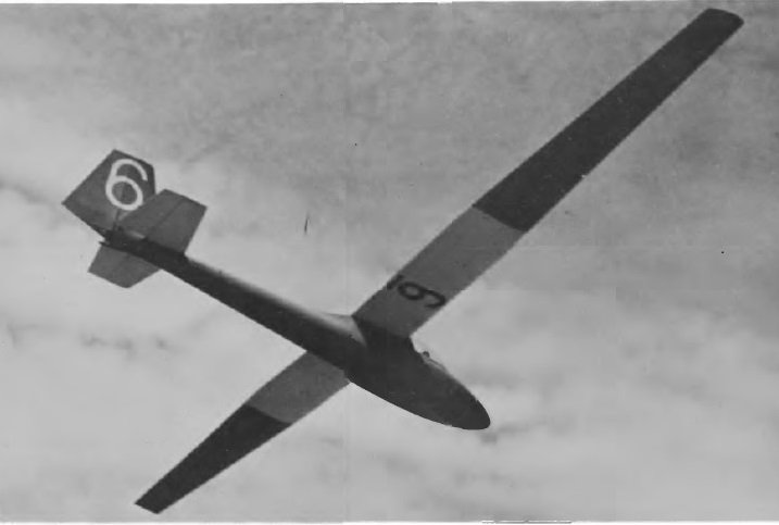
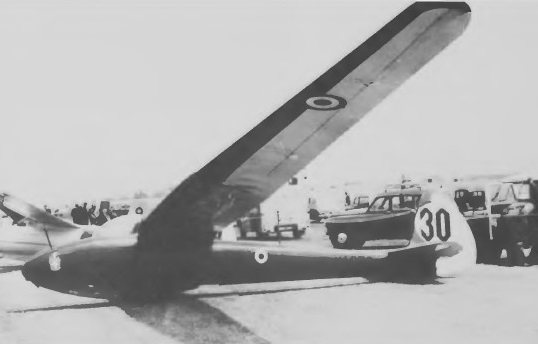
Intended as a successor to the T42 Eagle the Capstan side-by-side two-seater is designed to be suitable for all stages of dual instruction, and also for club or private owner use; a wide cg range enables it to be flown solo when required.

Design work began in 1960 and the prototype, the T49A first flew on 4 November 1961; this differed slightly from the T49B production version, having a smaller fin and rudder.

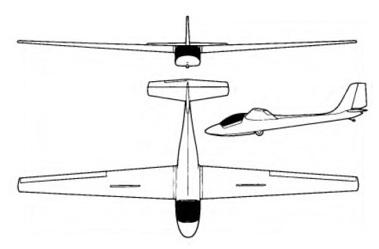
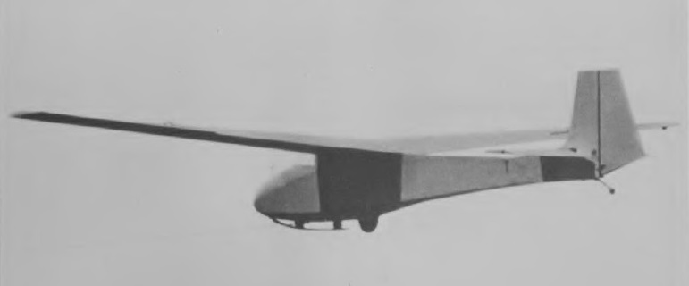
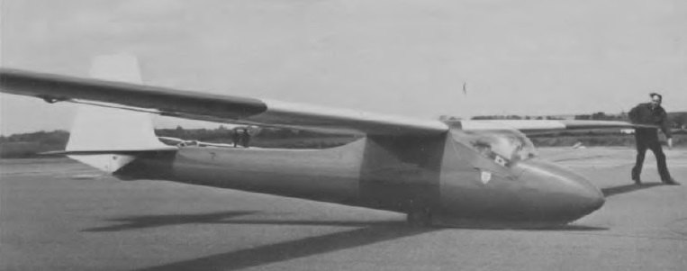
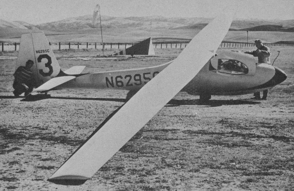
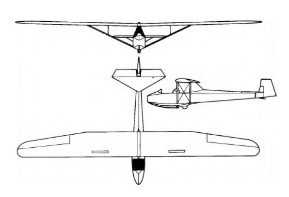
Of conventional wooden construction, the Capstan has glassfibre covering for the nose section and other double curvature panels and fairings, with ply and fabric covering elsewhere. The cantilever high-set single-spar wings have a plywood leading edge torsion box and fabric coveirng aft of the spar; there are dive brakes in the upper and lower wing surfaces and the ailerons are plywood-covered. The wings are attached to each side of the fuselage with three pins, making for ease of rigging. The forward fuselage is made up of spruce frames attached to a central keel box and is covered in glassfibre, while the rear fuselage is a braced wooden girder structure, with a bottom skin of plywood and the top and sides fabric-covered. The fixed surfaces of the cantilever tail unit are plycovered and the control surfaces fabric-covered; there is a trim tab in the starboard elevator. There is a nose skid under the forward fuselage mounted on a full-length rubber shock absorber, and a fixed Dunlop monowheel with a band brake, plus a leafspring tailskid. The two pilots sit under a rearward hinged one-piece Perspex canopy, and all controls are duplicated except for the tow release and elevator trimmer.

Production started in the spring of 1963, and altogether 31 T49B Capstans were built, plus two more constructed in New Zealand by Mr Fred Dunn from kits supplied by Slingsby; price of the T49B was £1,750 in October 1963.

The T49C Powered Capstan was a standard Capstan fitted with a 45hp Nelson H-63CP four cylinder two-stroke engine mounted on a pylon behind the cockpit and driving a pusher propeller. Small wing tip wheels and a tail wheel instead of a skid were fitted. The prototype, G-AWDV, first flew on 15 February 1968 at Wombleton, Yorkshire, but was burnt out in the fire that destroyed Slingsby’s factory in November that year. It had been intended to make complete ‘power eggs’ available to convert existing Capstans but this idea was not proceeded with. The T49C had a maximum level speed of 85mph, a sea level rate of climb, when flown solo, of 510ft/min, and a take-off run of 420ft with two pilots.

The Capstan was Slingsby’s last wood two-place design.

T.49 Capstan
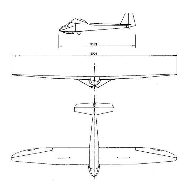
Wing span: 16.76 m (55 ft 0 in)
Length: 8.07 m (26 ft 6 in)
Height: 1.58 m (5 ft 2.5 in)
Wing area: 20.43 sq.m (220 sq.ft)
Wing section: NACA 63-620/6412
Aspect ratio: 13.75
Empty weight: 345 kg (761 lb)
Max weight: 567 kg (1,250 lb)
Water ballast: None
Max wing loading: 27.75 kg/sq.m (5.68 lb/sq.ft)
Max speed: 117 kt (217 km/h)
Stalling speed: 32.5 kt (60 km/h)
Min sinking speed: 0.66 m/sec (2.17 ft/sec) at 37.5 kt (70 km/h)
Max rough air speed: 80 kt (148 km/h)
Best glide ratio: 30 at 41 kt (76 km/h)

T.49B Capstan
Wing span: 16.78 m / 55 ft 0 in
Wing area: 20.43 sq.m / 219.9 sq.ft
Length: 26 ft 6 in
Height: 5 ft 2.5 in
Empty Weight: 345 kg / 761 lb
Payload: 222 kg / 489 lb
Gross Weight: 1250 lb /567 kg
Wing Load: 5.68 lb/sq.ft / 27.7 kg/sq.m
Aspect ratio: 13.75
L/DMax: 30 @ 84 kph / 45 kt / 52 mph
No. of Seats: 2
MinSink: 0.79 m/s / 2.17 fps / 1.54 kt at 43.5 mph
Max speed: 135 mph
No. Built: 34
Airfoil: NACA 63-3-620
Structure: all wood, fiberglass nose and fairings

T.49B Capstan
Engine: Nelson, 45 hp / 34 kW
Wing span: 16.78m / 55ft
Wing area: 20.43sq.m / 219.9sq.ft
Aspect ratio: 13.78
No. of Seats: 2
Airfoil: NACA 63-3-620
Structure: all wood, fiberglass nose and fairings

Slingsby T-46

A two seat, side by side glider, a developed version of the Type 21B with larger wing span, enclosed cockpit, and revised tail unit. Braced wing, with airbrakes, no flaps.

Wing span: 17.22m / 56ft 6in.
Length: 8.15m / 26ft 9in
Wing span: 25.36m / 273.75 sq. ft
Aspect ratio: 11.7
Wing sections: Gottingen 535 at root, Sym. at tip

Slingsby T-45 Swallow / Reussner Swift

Described as ‘a poor man’s Skylark’, the Swallow single-seater was intended to meet the need for a small moderately-priced high performance sailplane for clubs and the private owner.

Slingsby T.45 Swallow Article

Of conventional wooden construction, the Swallow has cantilver high-set wings of spruce and plywood, with single spars, plywood covering and a leading edge torsion box; the wooden fabric covered ailerons are unbalanced and there are dive brakes in the wing upper and lower surfaces. The forward fuselage is a plywood semi-monocoque while the rear portion is a braced structure of spruce and plywood with fabric-covered sides. The wooden tail unit has ply covering for the fin and tailplane and fabric covering for the rudder and elevators. Landing gear consists of a rubber-sprung skid under the nose, a fixed unsprung monowheel and a tailskid.

The prototype first flew on 11 October 1957 with a span of 39ft 4in (12m) but this was increased to 42ft 9.25in to improve performance. The type, then unnamed, got its name when the prototype, flown by John Reussner, crashed and ended up hanging from some telephone wires – ‘just like all the other swallows’, said Mr F. N. Slingsby, who witnessed the accident and promptly dubbed the type Swallow. Reussner later acquired the prototype and rebuilt it as a standard Swallow; it became BGA 865 in October 1958. It was later modified to his own ideas as the Reussner Swift, with the span increased to 15m (49ft 2.5in) by extending the wing roots, lengthening it by a 1ft insert in the rear fuselage, and fitting a revised canopy similar to that of the Swallow 2. As the Swift it became BGA 966 and crashed on 24 November 1963 at Netheravon, Wiltshire.

The Swallow 1 prototype was followed by the Swallow 2 production version which differed in having a revised canopy of slightly different shape; the type was sold to nine different countries and a total of 106 were built up to 1968 before production was terminated by the fire at Slingsby’s Kirbymoorside factory, plus 10 more constructed from kits supplied by Slingsby for amateur constructors.

The Royal Air Force operated 4 (known as the Swallow T. Mk. 1) in its air cadet training program.

The Swallow 3 project of January 1968 was a variant designed for that year’s Swallow Competition organised by the cigarette firm of W. D.& H. O. Wills, with which British sailplane pilot Philip Wills was associated; the Mk 3, which was not built, had a revised nose shape incorporating a flush-fitting one-piece canopy with no step, and the wing span was increased to 24ft and the area to180sqft.

While Fred Slingsby was taking photgraphs of the prototype T.45 at Sutton Bank, John Reussner crashed and ended up with the glider hanging up in telephone wires, ‘just like all the other Swaallows’ commented Fred. ‘Just for that we’ll call it The Swallow’.

John Reussner rebuilt the prototype as a standard Swallow, with a c/no of JCR.1, and it received a BGE C of A in October 1958, BGA 865. It was later modified and final appeared as the Swift.

The modifications included extending the wingspan to 15m by adding a parallel chord section to each wing root, lengthening the fuselage by 1 foot, this added to the rear fuselage between the trailing edge of the wing and the tailplane. A revised canopy was also fitted.

The Reussner Swift was allocated c/n JCR.2and received a C of A BGA.966 in August 1960.

It crashed at Netheravon, Wiltshie, on 24 November 1963 and was written off. The pilot was killed, but it was later established he had suffered a heart attack while in the air.

T.45 Swallow
Span: 13.2m / 42 ft 9.25 in
Length: 7.04 m / 23 ft 2 in
Height: 1.58 m / 5 ft 2.5 in
Wing area: 13.55 sq.m / 145.9 sq.ft
Aspect ratio: 12.6
Wing section: NACA 63-618/4412
Empty Weight: 195 kg / 431 lb
Payload: 122 kg / 469 lb
Gross Weight: 317 kg / 700 lb
Wing Load: 4.8 lb/sq.ft /23.4 kg/sq.m
Water ballast: None
Max speed: 141 mph / 122.5 kt / 227 km/h
Stalling speed: 33.5 kt / 62 km/h
Max rough air speed: 75 kt / 139 km/h
MinSink: 0.76 m/s / 2.5 fps / 1.48 kt at 36 kt / 67 km/h
L/DMax: 26 @77 kph / 42 kt / 48 mph
No. of Seats: 1
No. Built: 116
Structure: wood and fabric

Reussner Swift
Wingspan: 15.0 m / 49 ft 2 in
Length: 7.37 m / 24 ft 2 in

Slingsby T-43 Skylark 3

Skylark 3

The T41 Mk 2 was followed by the T43 Skylark 3 single seater, an enlarged and developed verison suitable for Open Class competition; this had the wing span increased by nearly 12ft to 59ft 8.25ft (18.19m) and the aspect ratio to 20.5, while the tail surfaces were enlarged, just as the Mk 2’s tail unit had been larger than the Mk 1 ‘s.

All the Mk3 variants had the same all-wood construction with plywood covering as the Mk 2, and a similar high-set laminar flow three-piece cantilever wing of spruce and plywood with air brakes in the upper and lower surfaces. The wing has a main spar and a light rear spar to carry the ply-covered ailerons, and is plywood-covered to the rear spar with a fabric-covered trailing edge. The wooden cantilever tail unit has a plywood-covered fin and tailplane and fabric-covered rudder and elevators. The landing gear is very similar to the Mk 2’s, with a tail bumper as an alternative to the tailskid, and the monowheel can be replaced by jettisonable dolly wheels. The pilot sits under a one-piece blown canopy which hinges sideways to open, and he is provided with an adjustable seat and rudder pedals. The wingtips and front fuselage of fibreglass.

The prototype Mk 3 first flew in July 1955 and there were several sub-types; altogether 65 Mk 3s of all variants were built, and a Skylark 3B flown by the Argentine pilot Rudolfo Hossinger won the Open Class in the 1960 World Championships in Germany.

Slingsby T.43 Skylark 3 Air Test

The Skylark 3A, of which seven were built, was the original Mk 3 variant with a length of 24ft 9in, and the Mk 3B had the cockpit moved forwards by 3in to compensate for the rearward movement of the cg caused by the larger tail; the elevator mass balances were also repositioned and the 3B’s length was 25ft. Altogether 24 Mk 3Bs were built, and both 3As and 3Bs later had the all-up weight increased to 830lb by a retrospective modification.

The Mks 3C and 3D, two examples of each of which were built, were the same as the 3A and 3B respectively but had the wing spars strengthened to meet BCAR and ARB requirements.

The Skylark 3E was a ‘one-off’ experimental version (serial BGA 480) with outer wings of a different NACA 64-series section and reduced chord ailerons, but was otherwise the same as the Mk 3B; it was later converted back to this standard. The Mk 3F was the same as the 3B but had geared tabs added to the ailerons, a modified tailplane and elevator plan form of greater span, and an all-up weight of 830lb; 25 of this variant were built plus five more constructed from kits supplied by Slingsby.

Skylark III

Last variant was the Skylark 3G, which was the same as the 3F but with increased span ailerons of reduced chord with the geared tabs removed; four Mk 3Gs were built.

Skylark 3
Wing span: 18.19m / 59.7ft
Wing area: 16.1sq.m /173.25sq.ft
Aspect ratio: 20.5
Airfoil: NACA 63-3-620/4415
Length: 7.62 m / 25 ft 0 in
Empty Weight: 272kg / 600lb
Payload: 104kg / 230lb
Gross Weight: 830lb / 376kg
Water ballast: None
Wing Load: 4.8lb/sq.ft / 23.36kg/sq.m
Max speed: 116.5 kt / 216 km/h
Stalling speed: 31 kt / 58 km/h
No. of Seats: 1
L/DMax: 32 @ 79 kph / 43 kt / 49 mph
MinSink: 0.61 m/s / 2.0 fps / 1.18 kt

Skylark 3B
Span: 59 ft 8.25 in
Length: 25 ft 0 in
Height: 5 ft 9 in
Wing area: 173.3 sqft
Aspect ratio: 20.5
Empty weight: 547 1b
Max weight: 830 lb
Max speed: 134 mph
Min sinking speed: 1.84 ft/sec at 40 mph
Best glide ratio: 36:1 at 46 mph

Slingsby T.42 Eagle

The Eagle high performance tandem two-seater was originally desinged to meet possible ATC requirements and was developed from the Slingsby T36 two-seater project, itself a development of the Sky; the Eagle also owed something to the Skylark series.

Of conventional wood and fabric construction, the Eagle has a high wing of NACA laminar flow section with a main spar and a light secondary spar to carry the plywood-covered ailerons; the wing is plywood covered to the rear spar, the trailing edge being fabric-covered. The wooden fuselage is of braced girder-type construction, with a glassfibre- and ply-covered nose and fabric-covered rear fuselage. The fin and tailplane are ply-covered and the rudder and elevators fabric-covered. Landing gear consists of a fixed monowheel, a nose skid under the forward fuselage and a tailskid. There is a one-piece Perspex canopy and the two pilots have provision for backtype parachutes; the rearmost pilot sits under the wing.

The T42 Eagle 1 prototype first flew on 12 June 1954 and had a cantilever three-piece wing with a slightly swept forward centre section of 20ft span, air brakes in the centre section and no flaps. The second prototype, the T42A Eagle 2, first flew in May 1956 and had a centre section span of 13ft 10in, with a cut-out in the leading edge to accommodate the rear cockpit; the air brakes were repositioned to the outer wings.

The Eagle 2 won the two-seater class in the 1956 World Championships at St Van, France, flown by Commander H. C. N. Goodhart and Captain Frank Foster; its success was the more gratifying because it was not designed as a contest sailplane but rather as a type for advanced training and cross-country soaring, to enable pilots to bridge the gap between the ‘C’ and ‘Silver C’ certificates.

The third prototype, the T42B Eagle 3, had the cockpit moved forward to avoid the Mk 2’s leading edge cut-out; this version went into production and a total of 17 was built, the price being £1,650.

In 1966-67 an Eagle 3, BGA 821, was converted into the T55 Eagle 4, also known as the Regal, this variant having the centre section span increased to 21ft 3in and the total span to 65ft 7.5in, or 7ft 5.5in more than that of the Eagle 3.

Slingsby T-41 Skylark 2

Skylark II

The T37 Skylark 1 had proved sufficiently promising to be developed into the T37B (later T41) Skylark 2, the prototype of which first flew in November 1953. This had the wing span increased to 48ft and a new semi-monocoque elliptical cross section fuselage with spruce frames and plywood skin which increased the length to 24ft 6in. The wing had top and bottom surface Schempp-Hirth type airbrakes. A fixed monowheel was introduced to supplement the nose skid, although this could be replaced by’jettisonable dolly wheels. The Mk 2 was of all-wood construction with plywood covering, like the Mk 1, and it also had a three-piece laminar flow wing. Its good performance made it popular both with clubs and private owners, and a total of 61 Mk 2s were built, plus two more from Slingby-supplied kits; about half this total were exported, production of the Mk 2 ending in 1962.

T-41B Skylark 2
Wing span: 14.63m / 48ft
Wing area: 13.37sq.m / 144sq.ft
Empty Weight: 209kg / 461lb
Payload: 99kg / 218lb
Gross Weight: 679lb / 308kg
Wing Load: 4.72lb/sq.ft / 23.02kg/sq.m
Aspect ratio: 16
L/DMax: 30
Airfoil: NACA 63(3)620
No. of Seats: 1
No. Built: 63
Structure: wood/ fabric/ CFRP moldings

T-41B Skylark 2B

Slingsby T-38 Grasshopper

Slingsby Type 38 Grasshopper

The Grasshopper is a primary single-seater glider intended to give basic training through short ‘hops’ on airfields or school playing fields. The open framework fuselage with a seat for the pilot was a simplified version of that of the Schulgleiter SG 38. It used the wings of the Slingsby Cadet Mk I and was designed to be easily dismantled for storage. The wing being wire-braced and without flaps or air brakes. A post war surplus of the T. 7 Kirby Cadet T.X. Mk. 1’s resulted in Slingsby building the primary T. 38 Grasshopper T.X. Mk. 1 with surplus T. 7 wings and tailplanes married to a new primary open fuselage. Most Cadet TX Mk Is were converted to Tutor standard as the T8 Cadet TX Mk 2 by fitting them with the Tutor’s longer span wings, and the spare wings of the TX Mk 1s were used to produce the Grasshopper TX Mk1.

It was launched by a V shaped elastic rope pulled by teams of cadets and could also be mounted on a pivoting tripod stand to enable the effects of the controls to be demonstrated.

The Grasshopper and the virtually identical EoN Eton were used by ATC Squadrons and RAF Sections of the Combined Cadet Force from 1952 to the late 1980s and many cadets made their first, somewhat brief, solo flights in these gliders.

Production began in 1952 and altogether 115 Grasshoppers were built.

Span: 39 ft 0 in
Length: 21 ft 1.5 in
Wing area: 174 sq ft
Aspect ratio: 8.73
Empty weight: 293 lb
Max weight: 550 lb
Max speed: 80 mph

Slingsby T37 Skylark 1

The T37 Skylark 1, first of the series, was built for a lark, according to Mr F. N. Slingsby-hence its name – and was an experimental single-seater with a three-piece laminar flow wing of 45ft span, intended to test various lateral stability devices to determine the best type of lateral control surface for use with a laminar flow aerofoil; the wing was of NACA 63-/64-series section and had very effective air brakes but no flaps. The fuselage was based on that of the T30 Prefect, with a one-piece canopy, the length being 20ft 11.5 in, and there was a main skid only plus a tailskid, no monowheel being fitted.

The first of two prototypes made its maiden flight in March 1953, and only the two Mk 1s were built partly as this version had, for that time, a very high stalling speed. But it had proved sufficiently promising to be developed into the T37B (later T41) Skylark 2.

Both of the single-seat Skylark 1 built were still flying in 1977.

Slingsby T.34 Sky

The Sky first flew in prototype form in September 1950 and was designed for the 1951 British National Championships, in which it came first and second, at the request of the newly-formed Royal Air Force Gliding and Soaring Association, who wanted a contest sailplane with a better performance than that of the well-known DFS Weihe. The Sky was basically an 18m span version of the 15m Slingsby Gull 4 with a longer fuselage and was at first known as the Gull 5 or the ‘Slingsby 18 metre’, but the name Sky was suggested by John Furlong as it was made up of the initial letters of Slingsby, Kirbymoorside where the firm’s works were, and Yorkshire.

The Gull 4 was intended to be Slingsby’s postwar 15m design, but did not go into production as the rival EoN Olympia was cheaper. The Sky, which resembled it, was of conventional wood and fabric construction; the production aircraft were designated T34A Sky 1 to distinguish them from the improved T34B Sky 2 intended for the 1954 World Championships but not, in the end, built. This version had NACA 64-/63 series wing sections instead of the Mk 1’s Gottingen 547 and NACA 2R 12 aerofoils, and revised squarecut wing tips and tail units. The high single-spar cantilever wings have a leading edge torsion box and a light secondary spar to carry the two-piece ailerons; the wing is fabric covered aft of the main spar and DFS-type air brakes are fitted in the upper surfaces, but there are no flaps. The fuselage is a ply-covered stressed skin wooden structure, and the landing gear is a single fixed monowheel behind an ash skid under the forward fuselage; there is a tail bumper and a jettisonable two-wheel dolly can be used in place of the monowheel. The tailplane is cantilever and the rudder and elevators are fabric-covered. The pilot sits under a one-piece moulded Perspex canopy and has adjustable rudder pedals; oxygen, radio and barographs can be installed for contest flying.

Although only 16 examples were built, the Sky high performance single-seater has a secure place in gliding history as being the first British-designed type to win the World Championships, which it did in 1952 flown by Philip Wills when this event was held at Cuatro Vientos, near Madrid; eight T34 Skys took part, also being flown by the Dutch and Argentine teams, and all but one of them were placed in the first 14, including the 3rd place taken by Robert Forbes. Philip Wills flew his Sky into second place in the 1954 World Championships at Camphill, Bedfordshire, and in the 1956 event this place was taken by Luis Vicente Juez of Spain in another Sky.

T.34 Sky
Span: 18.0 m / 59 ft 0.5 in
Length: 7.65 m / 25 ft 1.25 in
Wing area: 17.37 sq.m / 187 sq.ft
Aspect ratio: 18.7
Wing section: Gottingen 547/NACA 2R 12
Empty weight: 252 kg / 556 lb
Max weight: 363 kg / 800 lb
Water ballast: None
Max wing loading: 20.9 kg/sq.m / 4.28 lb/sq.ft
Max speed: 113 mph / 98 kt / 182 km/h
Stalling speed: 29 kt / 54 km/h
Max rough air speed: 72.5 kt / 134 km/h
Min sinking speed: 0.66 m/sec / 2.17 ft/sec at 39 mph / 33.5 kt / 62 km/h
Best glide ratio: 27.5:1 at 43 mph / 37 kt / 69 km/h

Slingsby T-31 Tandem Tutor

T-31B Tandem Tutor Trainer

The T. 8 Kirby Tutor (RAF Kirby Cadet T.X. Mk. 2) with a 13.24 m/ 43.4 ft. tapered wing evolved into the T.31 Tandem Tutor (RAF Kirby Cadet T.X. Mk. 3) two-place trainer.

The Tandem Tutor can be flown either dual or solo, and differs from the single-seat Tutor chiefly in having the forward fuselage lengthened to accommodate the second cockpit. An extra V-strut over the rear cockpit windscreen supports the wing leading edge, and wing spoilers are usually fitted in the upper surfaces, although some Tandem Tutors do not have them, and flaps are not fitted. The forward fuselage is plywood-skinned and the rear fuselage is fabric-covered; the pilots have full dual controls. Landing gear is basically the same as the Cadet’s with a monowheel, a skid under the forward fuselage and a tailskid.

The Tandem Tutor was designed by F. N. Slingsby, first flew in prototype form in September 1950. A two-place development of the single-place T.8 Tutor using the same wings with additional bracing. Early production T.31’s had no aids for approach control, but spoilers were added to later models, and retrofitted to most examples.

This was selected as a standard ATC trainer, being known as the Cadet TX Mk 3 by the RAF, and altogether 131 were built for the ATC and 69 for gliding clubs and other civil customers; 14 more were built from Slingsby-supplied kits and a number of Tandem Tutors were also built from Government surplus spares. The Royal Air Force used T.31B’s (known as the Kirby Cadet T.X. Mk. 3) in its air cadet organization from 1950 to the mid 1980’s. One ‘Mark 3’ made over 120,000 flights totaling 6,000 hours in this period.

Variations:
Martin & Wilkinson Cadet III

T.31 Tandem Tutor
Wing span: 13.2 m / 43 ft 3.75 in
Wing area: 15.8 sq.m / 170 sq.ft
Airfoil: Gottingen 426
Aspect ratio: 11.1
Length: 7.1 m / 23 ft 3.75 in
Empty Weight: 176 kg / 388 lb
Payload: 442lb/ 200kg
Gross Weight: 830 lb /376 kg
Wing Load: 4.88 lb/sq.ft/ 23.8 kg/sq.m
Water ballast: None
Max speed: 81 mph / 70 kt / 130 km/h
Stalling speed: 33 kt / 61 km/h
L/DMax: 18 @ 73 kph / 39 kt / 45 mph
MinSink: 1.05 m/s / 3.48 fps / 2.06 kt at 42 mph / 36 kt / 67 km/h
No. of Seats: 2
No. Built: 200
Structure: wood/fabric