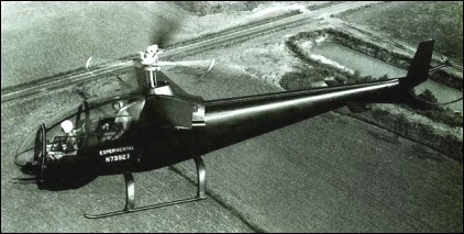
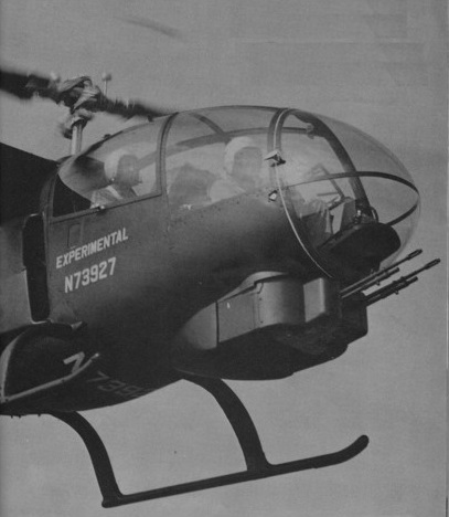
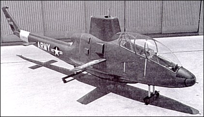
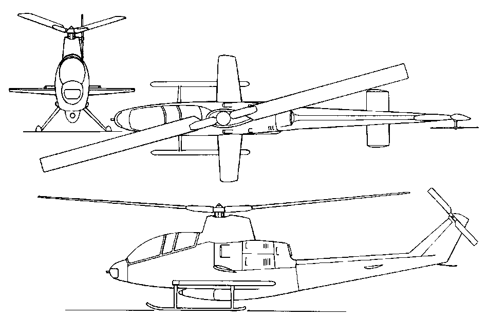
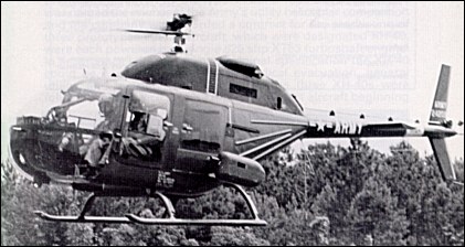
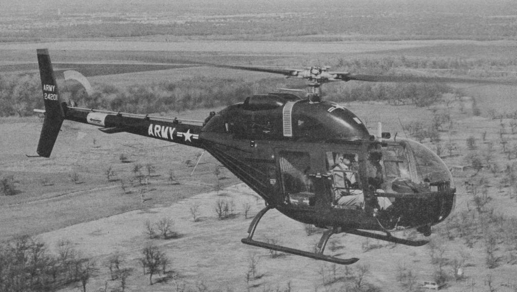
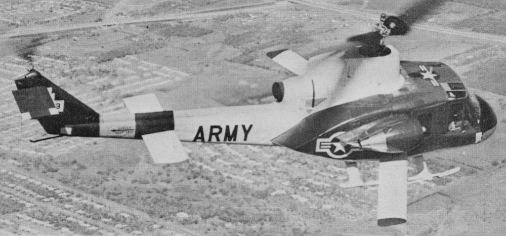
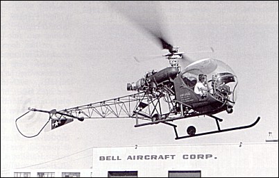
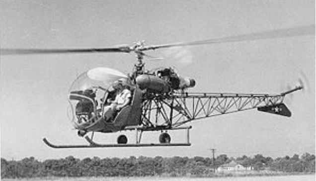
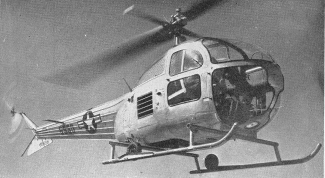
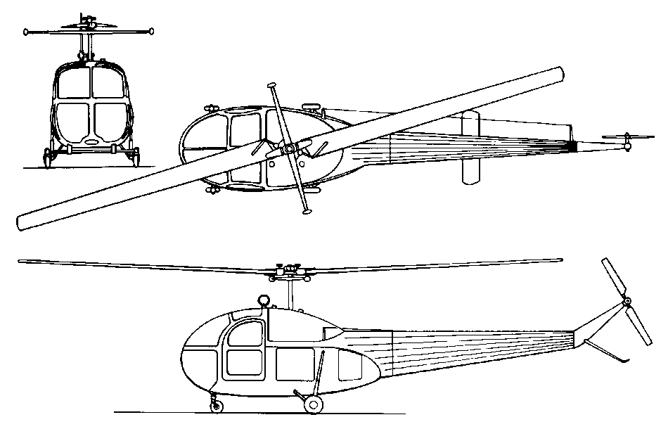
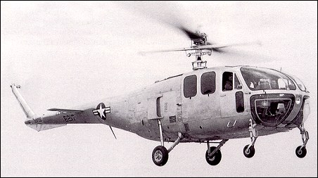
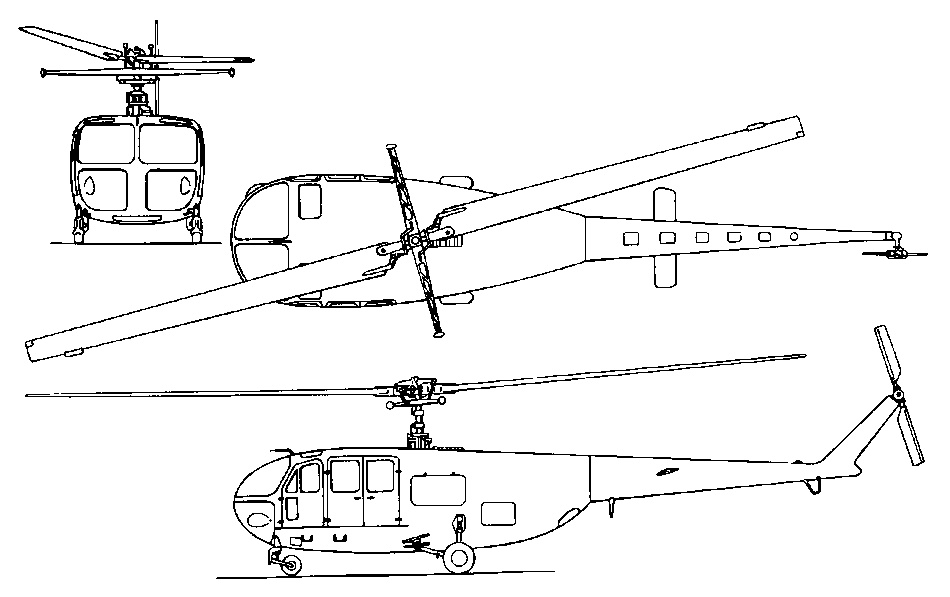
Bell proposed the Iroquois Warrior for an interim programme which later became known as AAFSS or Army’s Advanced Aerial Fire Support System and, by December 1962, also modified an OH-13S as an armed helicopter which would combine the desired combat potential with the desired flight performance. The aircraft, known by Bell as Model 207 Sioux Scout embodied a low drag profile, crew of two seated in tandem with integrated weapons, sighting systems and equipment. A new profiled fuselage was made from a Model 47J-2 rear fuselage mated with an all-new glazed streamlined cockpit with reinforced plastic bubble. The landing gear was of the skid-type. As powerplant the Sioux Scout retained the 260hp turbo-supercharged Lycoming TVO-435-A1A and had the rotor system of the OH-13S. The crew was seated in tandem with dual flying controls. The pilot was above and behind the gunner who controlled an Emerson Electric TAT-101 chin-turret armed with two 7.62mm machine-guns. This turret was a privately-funded modified version of the M-60-C gun barbette which, linked to the movement of the gunner’s sight, could swivel 200deg in azimuth, and 15deg above and 45deg below the horizon.
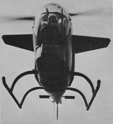
The Sioux Scout also incorporated stub wings which had been designed to carry auxiliary fuel tanks as well as providing extra lift. Flight tests showed that these wings also improved high-speed turning capability. Several types of wings were evaluated on the Model 207, as well as various types of cowlings, tailboom elevators and fins.
The sole Model 207 prototype (N73927) made its maiden flight on 27 June, 1963, with Al Averill at the controls. This flight lasted ten minutes and by 25 July, the Sioux Scout had logged 18hr 30min flying. At the end of 1963, the aircraft was passed to the US Army for further evaluation by pilots of the 11th Air Assault Division at Fort Benning in Georgia. The Army pilots were surprised at the Model 207’s capabilities and asked that such an aircraft but with a more powerful engine be promptly developed.
In fact, albeit a highly promising concept, the Sioux Scout was somewhat limited in true combat capability and had no future. Only the one was built.
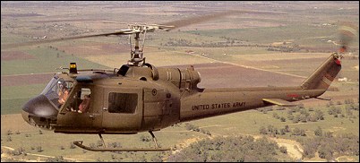
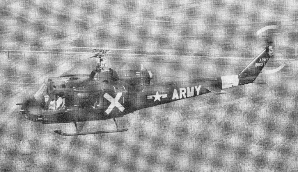
In June 1962, Bell invited US Army officials to Fort Worth to see the mock-up of a combat helicopter. Known as the Design D-255 “Iroquois Warrior” and wearing false s/n 62-00255 (HU-1F), the relatively small helicopter retained several features of the UH-1 and had a low silhouette, narrow profile and a small cross-section forward fuselage. This streamlined fuselage with retractable skids had been designed for maximum speed, armament payload and crew efficiency. It featured a stepped cockpit configuration with the gunner placed just in front and below the pilot. Armament included a ball-turret in the nose, a streamlined gun compartment under the fuselage and various external loads. Although innovative, the D-255 retained the powerplant as well as the basic transmission and rotor system of the UH-1C in order to reduce maintenance and development time as well as to cut costs. On 30 August, 1962, the so-called Howze Board, a study group led by Gen. Hamilton H. Howze, submitted its final report in which recommendations were made for the creation of Air Cavalry Combat Brigades and the design of specific aircraft for that purpose. Bell decided to go further in its company funded attack helicopter research programme but on a reduced cost basis. The first step was to build a flying test-bed by transforming a standard Model 47 into the Model 207 “Sioux Scout”. The flight tests were highly successful but the Army pilots called for a larger turbine-engined aircraft. Bell went to work on a redesigned scaled-down version of the D-255, known as the D-262, which was entered in the 1964 Advanced Aerial Fire Support System (AAFSS) competition calling for a fast, armoured, heavily-armed helicopter for which Lockheed (with the AH-56A Cheyenne) and Sikorsky (with the Model S-66) were eventually selected.
In 1965, the U.S. Army issued a Request for Proposal for what it called the Composite Aircraft Program. Composite, in this case, was for a vehicle that would have both helicopter and airplane characteristics, specifically, looking for a single aircraft to replace both the CH-47 helicopter and the C-7 “Caribou”. Three contractors were selected to perform design studies in 1966 and Lockheed and Bell were chosen to perform further exploratory definition studies, which were completed in September 1967. However, the Army dropped the development due to limited funds. Bell decided in 1968 to continue development for a proposed civil tilt-rotor aircraft, designated the Model 300. Initial work led to the design for a 4285kg aircraft powered by two Pratt & Whitney PT-6 engines powering 7.6m diameter rotors. One-fifth scale aerodynamic and aeroelastic models were built and tested extensively from 1969 through 1973. Full size rotor and rotating mechanisms were whirl tested to determine their hover performance and then tested in 1970 at the NASA Ames 12m x 24m wind tunnel at various rotation speeds, angles, and airspeeds up to the maximum tunnel speed of 370km/h. The rotor met or exceeded all performance and stability predictions. Then, in 1972, NASA and the U.S.Army Air Mobility Research and Development Laboratory jointly started the Tiltrotor Research Aircraft Program. Since the Tiltrotor Research Aircraft Program was to be strictly a research program and would not lead to the production of an operational aircraft, costs were to be kept under control by not making weight minimization a major factor and encouraging the use of off the shelf components. Advanced technologies like fly-by-wire and composite structures were to be avoided. Weight growth and performance shortfalls would be tolerated in order to minimize cost and schedule impacts. Even the number of aircraft to be built was a factor. The two aircraft option was selected because of the high accident rate experienced by most other VTOL research programs. Bell’s proposal started with the Model 300’s design and evolved it into Model 301. Bell kept the rotor and transmission, but replaced the engines with the more powerful Lycoming T-53 because of the requirement to hover with only one engine and the greater empty weight and useful loads required. Another benefit of the engine switch was that the T-53 already had an oil system that could operate with the engine pointed vertically, which had been developed for the CL-84 program. Bell’s proposal was submitted on January 22, 1973, and comprised 300 volumes weighing 350kg. Bell’s proposal was selected in April 1973. NASA awarded contract NAS2-7800 for $28 million for the final design, fabrication, and preliminary testing of two XV-15s on July 31. The total estimated cost of the six-year program was $45 million. The 12.8m long fuselage design was of a conventional aircraft, semi-monocoque, , and using light alloy material. There was no fuselage pressurization, and the structure was stressed from +3 to -0.5 G. The airframes were designed for minimum service lives of 1000 flight hours over five years. The tricycle landing gear came from the Canadair CL-84. It utilized Goodyear magnesium main and nose wheels, and Goodyear hydraulically operated magnesium/steel disc brakes. The full-swiveling nose wheel incorporated shimmy dampers and a centering device. It retracted into a bay forward of the cockpit. The main wheels retracted into external pods on each side of the fuselage. A switch on the main gear strut prevented inadvertent gear retraction and tilting of the pylons more than 30 degrees from vertical when the aircraft was on the ground. The landing gear was structurally designed to withstand a touchdown sink rate of 3m per second at full gross weight. A 14500kg/sq.m nitrogen gas system provided for emergency extension in the event of a hydraulic failure. The H-tail consists of a horizontal stabilizer with a vertical stabilizer on each tip. This configuration was selected to provide improved directional stability at and near zero yaw angles. Rockwell International’s Tulsa Division built the fuselage and tail units under subcontract. Two pilots sat side-by-side in Rockwell-Columbus LW-3B ejection seats, entering through a door on the right side of the cargo compartment. The flight deck was heated, ventilated, and air conditioned, but not the cargo compartment. The cabin could accommodate nine personnel if not filled with test equipment. The wing measures 9.75m across, has a constant chord measuring 1.6m, and a area of 15.7sq.m (one of the design requirements was that the XV-15 be able to fit in NASA Ames’ 12m x 24m wind tunnel, which influenced the wingspan and rotor size). It is swept forward 6.5 degrees, not for any futuristic aerodynamic reasons, but to insure there would be adequate clearance when the rotor blades flex in airplane mode. Wing dihedral is 2 degrees. Along the trailing edge, a flap measuring 1sq.m occupies the inboard third, and a flaperon measuring 1.85sq.m occupies the outer two thirds. The flaps can be deflected down to 75 degrees to help provide additional lift at low speeds. In hover, the flaps and flaperons deflect downward to reduce slipstream interference by the wing. The problems with the wing/rotor/pylon stability that plagued the XV-3 were eliminated by designing a very stiff wing and nacelle/wing attachment, and by placing the rotor hub as close to the wing as possible. Each wing holds two fuel bladders that form a single crashworthy fuel tank in each wing. Together they hold a total of 830 litres. The pump in each wing tank is powered from a different electrical system. In the event of a pump failure, both engines can feed from the same tank, or in the case of an engine failure, one engine can feed from both tanks. Cross feeds activate automatically in the event of a pump failure to assure uninterrupted fuel flow to both engines. In the event of a complete loss of electrical power to both pumps, the engine driven pumps still can maintain adequate fuel flow. An Avco Lycoming LTC1K-4K engine, a modified version of the standard T53-L-13B engine, is mounted at each wing tip. They are rated at 1250shp for continuous operation, 1401shp for 30 minutes, 1550shp for 10 minutes for take-off, and 1802shp for two minutes for emergency power. Power is transmitted from the engines to the rotors using a coupling gearbox and transmission, which reduce the engine speed of approximately 20000 revolutions per minute down to a rotor speed of about 565 revolutions per minute in hover. The three-bladed, semi-rigid rotors measure 7.6m in diameter and have a 36cm chord. They were made of stainless steel and have a large amount of twist. (In July 1979, Bell received a contract from Ames for preliminary design of a composite rotor blade that would offer improved performance and increased life expectancy, compared to the existing metal blades. A set eventually was tested, but did not work well.) There are no flapping hinges, but the rotors can flap forward or aft as much as 6 degrees. To assure power to both rotors in the event of an engine failure, a shaft that runs through the wing interconnects the two transmissions. As a result of the interconnect, both rotors turn when the first engine starts. In the event of a double engine failure, both rotors will autorotate at the same speed. The nacelle tilt can be varied from horizontal to 5 degrees aft of vertical. Interconnected double ballscrew actuators operate the tilt mechanism in each nacelle. This assures that both nacelles always will be at the same position. The interconnected drive shafts and redundant tilting mechanisms permit single engine operation and fail-operate tilt capability. The cockpit has dual controls and resembles a helicopter cockpit, including a collective stick. The flight controls are designed to permit single pilot operation from either seat. In airplane mode, the control columns and rudder pedals work conventionally. In hover mode, the stick functions as a cyclic pitch controller. The mechanical mixing unit does everything needed to convert the controls from the helicopter mode to the fixed wing mode. Control authority between helicopter and airplane mode is phased in as a function of the nacelle tilt angle. This includes changing the rotors from cyclic pitch control in vertical flight to constant speed control for fixed wing flight. In airplane mode, the collective lever can still be used as a power lever. Moving the collective lever causes the throttles on the center console to move. Two switches, mounted on the collective lever and operated by the pilot’s thumb, control the nacelle tilt angle. One pivots the nacelles from end to end in about 12 seconds and allows them to be stopped at any position. The other switch moves the nacelles between pre-selected angles of 0, 60, 75, and 90 degrees (relative to horizontal). To rotate the nacelles, electrical valves activate hydraulic motors. In the event of a complete electrical system failure, the pilot can manually open the valves using T-handles in the cockpit. This will drive the nacelles to the helicopter position. Sperry Rand built the original navigation/guidance system. A digital computer provides navigation and control information to the pilot using advanced mechanical and electronic displays. The Calspan Corporation of Buffalo NY designed the Stabilization Control Augmentation System to improve its flight characteristics. The XV-15 does not incorporate fly-by-wire. Ailerons, elevator, and rudder are hydraulically boosted with a triple hydraulic system. They remain active in all flight modes.
The XV-15’s empty weight is 4315kg with a vertical take off weight of 5865kg. This allows 495kg for instrumentation, 180kg for pilots, and 630kg of fuel, while leaving a few left over for growth. Original estimated performance included a maximum level speed of 610km/h, service ceiling of 8845m, and a range of 800km. None of these goals ever were achieved, but the XV-15 did achieve its primary objective of proving the practicality of the tilt rotor concept.
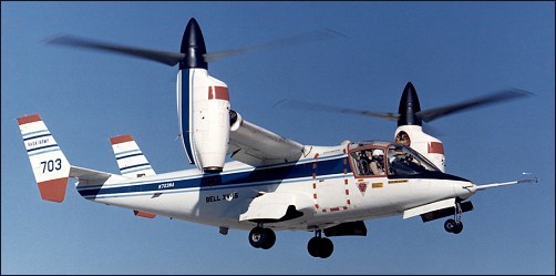
In April 1974, Rockwell International (Tulsa Division) received a contract for the construction of the fuselage and the tail assembly of the two XV-15 airframes. On 2 October, 1975, components of the first prototype were delivered to Bell Helicopter in Fort Worth where final assembly would be undertaken. Aircraft No.1 (c/n 00001, N702NA) was rolled out, at Arlington, on 22 October, 1976. Before tiedown dynamic tests simulating all flight modes, the XV-15 No.1 underwent an extensive integration checkout. Ground runs began in January 1977, and included 100 hours of system qualification tests on an elevated test stand in both the helicopter and airplane modes to demonstrate that the aircraft met final flight qualification requirements. The first hovering flight was performed on May 3, 1977, followed by hover and low speed evaluations. This short test effort consisted of only three hours of hovering during May. No problems that warranted corrections were uncovered. Following these flight tests, the transmissions and rotors were torn down, inspected and reassembled. Because of NASA’s insistence on full-scale wind tunnel tests before attempting a conversion, aircraft #1 was shipped by C-5A to NASA’s Ames Research Center in March 1978 for wind tunnel tests. These tests were conducted in the Ames 12m x 24m foot wind tunnel in May and June 1978. Twenty hours of tunnel tests were performed at airspeeds between 110 and 330km/h. Configurations consisted of the rotors in helicopter and airplane positions, and numerous intermediate positions that would be encountered during transition. No unusual characteristics were noted in any of the tests conducted. Following the wind tunnel tests, the #1 aircraft was torn down and refurbished at NASA Ames.
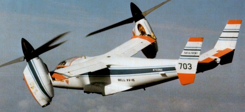
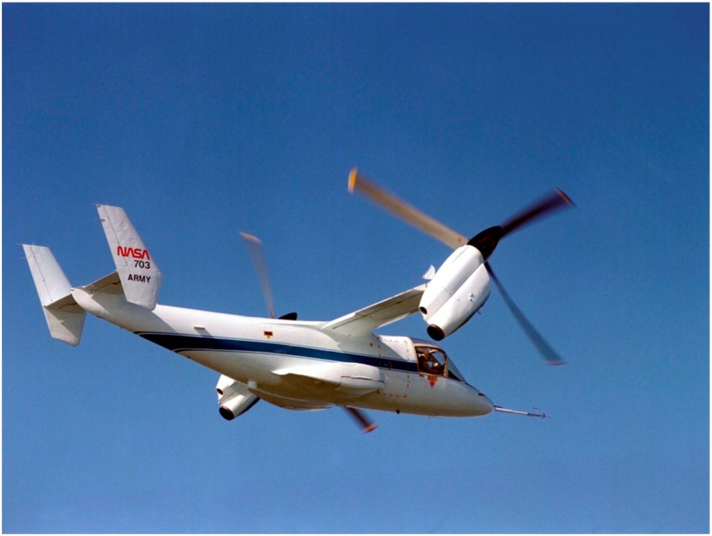
The second XV-15, #N703NA, was nearing completion. Since the program lacked funds to keep two aircraft on flight status, testing resumed with the #2 aircraft, beginning ground tests in August 1978 at Arlington. Numerous minor problems plagued the aircraft during these tests, including a stress corrosion crack in the left engine gearbox, a clutch misengagement, and foreign object damage within the transmission. It made its first hovering flight on April 23, 1979, with Ron Erhart and Dorman Cannon, Bell’s XV-15 project pilot, at the controls. Conversion tests soon began, starting by rotating the nacelles 5 degrees forward on 5 May 1979. Successive tests gradually rotated the nacelles closer to horizontal, until the first complete conversion was made on July 24, 1979. The XV-15 also achieved a forward speed of 295km/h on this 40 minute flight. On 21 April, 1980, No.2 prototype reached 485km/h at 2530m. In one year of testing, aircraft No.2 logged 40 hours flying.
The Navy became interested in the XV-15 and because of continuous funding shortfalls, the Naval Air Systems Command began providing funding in 1979 and 1980 to insure the XV-15 flight testing would proceed up through the completion of envelope expansion flights. In exchange, the Navy would be allowed to perform flight evaluations.
During the contractor test program, all potential failures were simulated in actual flight or on the ground. On December 5, 1979. an actual engine failure occurred when the turbine seized. The transmission interconnect system worked properly, and both rotors continued to turn as designed. The predicted speed of 555km/h true airspeed was demonstrated with maximum rated power at a 4880m density altitude in June 1980. The contractor flight test phase was completed in August 1980. The basic conversion corridor and airspeed/altitude envelope up to 16,000 feet was demonstrated. About 100 full conversions were made. Some resonance problems were uncovered, as is normal in any helicopter development, but they were fixed quickly. Upon completion of the contractor flights, XV-15 #2 was shipped to NASA’s Dryden Flight Research Center for continued testing, where it was joined by aircraft #1. Both XV-15s then operated at Dryden for a short period. XV-15 #1 returned to Bell in September 1981. Flight testing by both NASA and Bell continued into the 1980s, and the two XV-15s proved to be virtually free of any significant problems. Additional accomplishments that were demonstrated included:
1.7 hour cruise endurance in airplane mode.
Cruise speed of 425km/h.
Take off as helicopter, fly twice as fast as a helicopter, and deliver payloads on half the amount of fuel when traveling distances of greater than 185km.
Autorotation descents in helicopter mode, but never to a full touchdown.
STOL take-offs with the nacelles tilted between 60 and 70 degrees, at the maximum gross weight of 6765kg. For taxiing on wheels, it was found that tilting the nacelles forward of vertical only 1 degree was enough to start the XV-15 moving forward. Tilting the nacelles aft of vertical brings the aircraft to a quick stop. The XV-15 tends to rock a bit more than other aircraft because of the weight of the engines and props all the way out at the wing tips. In hover, roll control is provided by differential rotor collective pitch, pitch control by cyclic pitch, and yaw by differential cyclic pitch. For maneuvering in the hover mode, many of the maneuvers normally performed by moving the cyclic control are done by tilting the nacelles. A combination of rotor angle and cyclic pitch also is used to vary the pitch attitude without moving forward. By tilting the rotors forward and simultaneously putting in aft cyclic control, the nose will pitch down, giving improved visibility over the nose. Vertical liftoff is very easy, as the XV-15 holds attitude on liftoff. Lateral movement is accomplished by banking slightly so that the thrust has a small side component. The XV-15 can travel sideways at 65km/h with no tendency to turn into the wind. It can hover backwards up to 65km/h. Touchdown surfaces can have an uphill or downhill slant of up to 15 degrees. Single engine performance is relatively poor, with single engine hover possible under only a very few conditions. During conversion from hover to conventional flight, there is a tendency to lose lift and sink, requiring the pilot to add power, but this is normal on all VTOL aircraft. With the nose up and full aft stick, level stalls in the clean configuration give a slight vibration at 205km/h. The aircraft will begin to sink, but there is no wing drop or other bad effects. In helicopter autorotation mode, the best descent rate of 11m/s is achieved at 140km/h. At 165km/h, the descent rate increases to 20m/s. For final approaches, pilots use nacelle tilt angle instead of pitch inputs to control airspeed. The 630kg of fuel contained in the wings proved to allow for only about a 280km range. An auxiliary tank holding an additional 405kg eventually was added to the fuselage, which increased the range to about 520km. In March 1982, aircraft #1 made a demonstration tour of East Coast facilities, which included seven flight demonstrations at six different locations in eight days. One flight included a stop at the helipad at the Pentagon. While on the tour, the XV-15 flew 4815km and needed only routine daily preflight maintenance. Following this East Coast tour, #1 was modified at Bell’s Arlington facility to perform an electronics mission evaluation. Items added included an APR-39 radar warning system and chaff dispenser system. The aircraft departed for NAS China Lake in California in May, then on to Ft. Huachuca in Arizona in June, and finally on to San Diego for sea trials. Shipboard evaluations were performed aboard the amphibious assault ship USS “Tripoli” off the San Diego coast in July 1982. Fifty-four vertical landings and take-offs (of which five were STOL take-offs) were performed. Other mission related evaluations included over-water rescue and simulated cargo lifting, which were demonstrated in May 1983, and simulated air-to-air refueling, which was performed in September 1984. By 1986, both aircraft had accumulated a total of 530 flight hours, made 1500 transitions, and reached an altitude of 6860m (while still maintaining an 4m/s climb capability). In March 1990, #1 set numerous time to climb and sustained altitude records for this class of aircraft. These included a climb to 3000m in 4.4 minutes and to 6000m in 8.46 minutes, without even performing extensive climb tests to develop an optimal climb profile. It also sustained an altitude of 6860m with a dummy payload of 990kg in addition to more than 450kg of test instrumentation. Under the new JVX programme Joint Services Advanced Vertical Lift Aircraft Program) the XV-15 served as test-bed. In direct relation to the JVX programme, XV-15 No.1 was tested in Fort Huachuca to evaluate its ability to accomplish SEMA missions (Special Electronics Mission Aircraft); the aircraft was sent to China Lake to measure its radar signature and, on 2-5 August, 1982, off San Diego, Lieut-Cdr John Ball and Dorman Cannon conducted the initial shipboard evaluation on board the amphibious assault ship USS Tripoli (LPH-10). This evaluation included vertical and short rolling take-offs, hovering flights and vertical landings. On this occasion, one of the 54 XV-15 landings was the ship’s 60.000th. The aircraft was then sent back to Fort Worth to undergo a complete overhaul and to receive several modifications. By the end of August 1982, the two prototypes had logged 289 hours of flight testing. The two XV-15s were then used in a research programme to explore the limits of the operational flight envelope and assess its application to military and civil transport needs. Late in 1987, the XV-15, piloted by Dorman Cannon and Don Borge, demonstrated its capabilities in the civil transport role at Washington and Chicago. The Chicago demonstration was conducted from Miegs Field in the very heart of the city. As of June 1990, XV-15 #1 was based at Bell Helicopter’s Flight Research Center in Arlington, TX, for continuing engineering development. XV-15 #2 was based at Ames for continuing tilt-rotor research. The two aircraft had accumulated 825 hours. By 1990 the XV-15 was flown by over 185 pilots with widely varying experience and capability levels, including several low-time private pilots. Numerous admirals, generals, and at least one U.S. senator and one service secretary flew as guest pilots. Each flight consisted of a brief demonstration of helicopter, conversion, and airplane modes by a Bell test pilot. The guest pilot then took over the controls. After a few minutes of familiarization, he was talked through an airplane stall, single engine operation, and conversion/ reconversion at altitude. They then return to the airport for several take-offs and landings, usually converting to airplane mode and back to helicopter mode each trip around the pattern. Guest pilots rated the XV-15 as easy or easier than a helicopter to hover. Conversion was unanimously said to be straightforward, and with a low workload. Handling qualities in airplane mode were excellent. Most also noted the low interior noise and smooth ride. FAA test pilots also flew the XV-15 in order to evaluate its potential for certification of a civil tilt rotor aircraft. While they saw no technical reasons for not being effective in the civil role, they determined that a review of Part 25, which sets standards for large transport aircraft, and Part 29, which sets standards for helicopters, would be needed in order to establish appropriate certification criteria. XV-15 #1 remained in service at Bell’s flight research center, where it was used as a concept demonstrator and marketing tool for the V-22 Osprey that was by then being developed. It was flown regularly until August 1992, when it was damaged beyond economical repair. A mechanical failure in the control system caused the aircraft to roll over while it was hovering. The crew was not injured, but the wing and one nacelle sustained extensive damage. At the time of the incident, #1 had flown nearly 841 hours. The forward fuselage was salvaged and put to use as a simulator to help develop Bell’s upcoming civil tilt rotor aircraft. XV-15 #2 remained at Ames through the 1980s. In 1986, it was fitted with composite rotor blades built by Boeing Helicopter. Sporadic testing was accomplished through 1991, when it was stopped due to a problem with the blade cuff that resulted in an emergency landing. While the blade cuff was being re-designed, NASA decided to put the airframe down for a major airframe inspection that would be due soon, anyway. Program funds again ran out before the inspection could be completed. #2 would remain partially disassembled until mid 1994. It had accumulated just over 281 hours. With Bell anxious to resume tilt rotor development, they established a Memorandum of Agreement with NASA and the Army in 1994 which transferred XV-15 #2 to Bell and allowed them to return it to service at no cost to the government. The disassembled aircraft was shipped to Arlington, Texas, and the refurbishment and inspection began in mid 1994. The original metal rotor blades were put back on, and the aircraft resumed flight testing in March 1995. Much of Bell’s recent research has focused on reducing noise in order to make civil tilt rotor more acceptable for operating in crowded urban areas. Tests were being conducted to determine the major sources of noise. As of the end of 1998, the remaining XV-15 had accumulated a total of 530 flight hours and remained in service at Bell’s Arlington facility to continue developing and refining Tilt Rotor technologies.
In 1960 the US Army launched a design competition for a new aircraft which it certified as a Light Observation Helicopter (LOH). The specification called for four seats, a 181-kg (400-Ib) payload and cruising speed of around 193 km/h (120mph). Design proposals were put forward by 12 US helicopter manufacturers from whom Bell, HilIer and Hughes were each contracted to build five prototypes for competitive evaluation. From the tests which followed, the Hughes HO-6 (later OH-6A) was selected for production as the US Army’s LOH.
Bell 206A
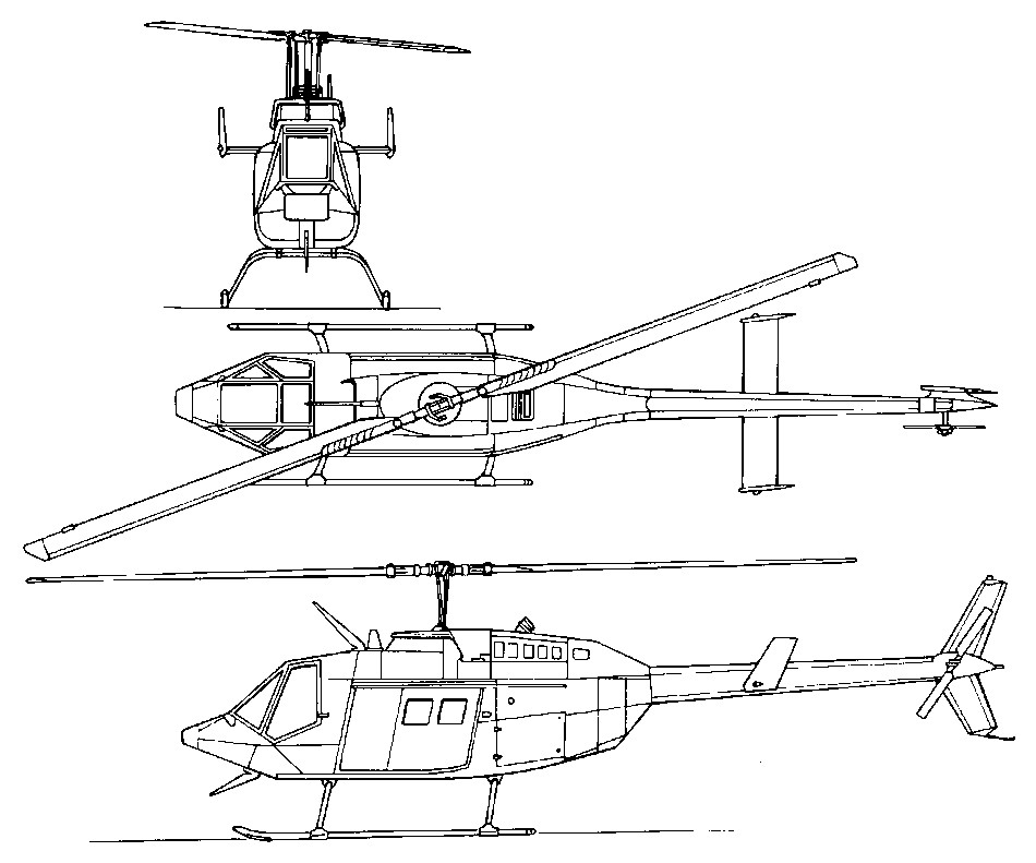
After losing the competition the company built a new prototype which it designated as the Model 206A JetRanger. This flew for the first time on 10 January 1966, and on 20 October 1966 this aircraft received FAA certification, after which it entered production for commercial customers, being built also by Agusta in Italy. The JetRanger was fundamentally the same as the OH-4A (formerly HO-4) prototypes, except for fuselage modifications to provide seating for five. It has been built in large numbers since 1966, and continues in production in 1989 in Canada under the designation Model 206B JetRanger III, having been the subject of progressive development and improvement programmes.
The US Army had expected to procure some 4,000 examples of the OH-6A, but became somewhat disenchanted with Hughes when the unit cost began to climb rather steeply, and the production rate to fall off. As a result, the US Army’s LOH competition was reopened in 1967 and, on 8 March 1968, Bell’s Model 206A “as announced as the winner, with production under the designation OH-58 Kiowa starting without delay; some 2,200 of these aircraft were delivered by the end of 1973. The OH-58 differs from the commercial JetRanger by having a larger-diameter main rotor, with detail changes in internal layout and the provision of military avionics. Initial deliveries to the US Army began on 23 May 1969, and within less than four months the Kiowa was deployed operationally in Vietnam.
Of the original 2,200 ordered for the US Army, 74 were withdrawn from the production line for delivery to Canada. The JetRanger was operated by the Canadian Armed Forces from December 1971 under the designation COH-58A, subsequently CH-136. An additional US Army contract for 74 aircraft was issued in January 1973 to replace those aircraft supplied to Canada.
In the early months of 1971, Bell began delivery of an improved Model 206B JetRanger II, and this subsequently replaced the Model 206A in production. It differed by having the more powerful 298-kW (400-shp) Allison 250-C20 turboshaft engine, the installation of which involved only minor airframe modification, so that it was possible also to provide kits for the upgrading of Model 206As to Model 206B standard. Australia acquired this version under the designation Model 206B-1 Kiowa, 12 being supplied by Bell and 44 produced under a co-production agreement. Commonwealth Aircraft Corporation in Australia was responsible for final assembly and only the powerplant and avionics came from the United States. Under a US Army development contract, a single OH-58A was equipped with a more powerful 313-kW (420-shp) Allison T63-A-720 turboshaft engine and an improved flat glass canopy. This modified aircraft has the designation OH-58C, and subsequently two additional OH-58A to OH-58C conversions were carried out to allow more extensive flight testing by Bell and the US Army. As a result of these tests, production modification of 275 OH-58As to a further-improved OH-58C configuration began in March 1978. Other versions include 12 OH-58Bs, similar to the OH-58A, supplied to the Austrian air force in 1976, and the US Navy has 40 TH-57A SeaRangers. These latter aircraft are dual-control trainers, which were ordered on 31 January 1968, to fulfil the requirement for a primary training helicopter for service with Naval Air Training Command at Pensacola, Florida. They are basically civil Model 206A JetRangers with US Navy avionics. The US Army Helicopter Improvement Programme (Ahip) involves the remanufacture of up to 578 OH-58A Kiowa scouts to OH-58D standard, incorporating 485kW Allison 250-C30R engines, an advanced composite four-blade main rotor, uprated transmission and tail rotor, a mast mounted sight and target designator, Stinger AAMs, CRT cockpit displays, and improved navigation and communications equipment. 23 were scheduled for delivery by the end of 1986, and conversions are being completed at a rate of five per month. Operationally, three OH-58Ds will lead five AH-64 Apaches, locating and designating targets for their Hellfire missiles. The OH-58D prototype flew in October 1983 and features a McDonnell Douglas/Northrop mastmounted sight and a Honeywell cockpit control and display sub-system. Up to 477 US Army Kiowas are planned for conversion to OH-58D standard. Powerplant is the 650 shp (485 kW) Allison 250-C30R turboshaft. Production of the JetRanger II ended in the summer of 1977, when it was replaced by the Model 206B JetRanger III. This introduced a more powerful version of the Allison turboshaft engine, offering further improvement in performance, and was the current production version in late 1981. This engine is also available as an installation kit to upgrade JetRanger Is to JetRanger III standard. The 1982 model JetRanger III included the C20J engine, in place of the C20B, an additional 14 gallon fuel tank capacity, bulge windows in the aft doors, and a lowered rear bench seat. The 206B-3 JetRanger III manufacture was transferred to Mirabel, Canada, in 1986, and also licence built in Italy by Agusta. The capability and reliability of the JetRanger family resulted in Bell developing a medium-lift version under the designation Model 206L LongRanger. The JetRanger III has skid landing gear, high-mounted tailboom and horizontal stabiliser. Two-blade teetering main rotor with preconed and underblung bearings; blades retained by grip, pitch change bearing and torsion-tension strap assembly; two-blade tail rotor; main rotor rpm 374 to 394. Hydraulic fully powered cyclic and collective controls and foot-powered tail rotor control; tailplane with highly cambered inverted aerofoil section and stall strip produces appropriate nose-up and nose-down attitude during climb and descent; optional autostabiliser, autopilot and IFR systems. Of conventional light alloy structure with two floor beams and bonded honeycomb sandwich floor, the transmission is mounted on two beams and the deck joined to the floor by three fuselage frames. The main rotor blades have extruded aluminium D-section leading-edge with honeycomb core behind, covered by bonded skin; tail rotor blades have bonded skin without honeycomb core. The aluminium alloy tubular skids are bolted to extruded cross-tubes. Tubular steel skid on ventral fin protect the tail rotor in tail-down landing. Special high skid gear (0.25m greater ground clearance) available for use in areas with high brush. Pontoons or stowed floats, capable of in-flight inflation, available as optional kits. The Rolls-Royce 250-C20J turboshaft, rated at 313kW for T-O; 276kW max continuous. Optionally, one Rolls-Royce 250-C20R/4 rated at 336kW for T-O. Transmission rating 236kW for T-O; 201kW continuous. Rupture-resistant fuel tank below and behind rear passenger seat, usable capacity 344 litres. Refuelling point on starboard side of fuselage, aft of cabin. Oil capacity 5.68 litres. The JetRanger III seats two side by side in front and three-seat rear bench. Dual controls optional. Two forward-hinged doors on each side, made of formed aluminium alloy with transparent panels (bulged on rear pair). Baggage compartment aft of rear seats, capacity 113kg, with external door on port side.
Bell 206 LongRanger
Bell 206 LongRanger
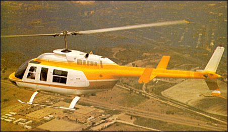
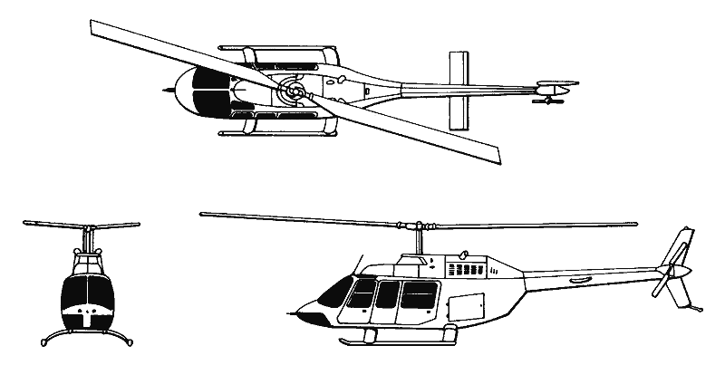
First announced on 25 September 1973, the Long Ranger was developed to meet a requirement for a turbine-powered general-purpose helicopter in a size and performance range between the five-seat Jet Ranger II and 15-seat Model 205A-1. This had the powerplant of the JetRanger III, and a fuselage lengthened by 0.63m (2ft 1in). With a capacity of 2.35cu.m, the LongRanger had good freight-carrying capability, and to simplify the loading of bulky items a double door was incorporated in the port side of the fuselage. Other improvements included the use of an advanced enlarged main rotor, plus introduction of the company’s patented Noda-Matic suspension system which gives much lower cabin vibration levels. Re¬design work included a new overhead structural beam, new transmission, and altered fuel setup. The two blade rotor system is basically the same as on the 206B, except that its di¬ameter has been extended by four feet. This actually gives the LongRanger a very slightly lower disc loading than the 206B. Also, an extruded, integral blade spar incorporating heavier elements at the tip and midsection replaces the older system by which weights were simply “tacked on” to the rotors for greater blade inertia. The original prototype Model 206L Long Ranger (N206L) flew for the first time on 11 September 1974 and production aircraft were delivered from October 1975. Accommodation provided for a pilot, co-pilot and five passengers. Alternative layouts allow for two stretchers and two ambulatory patients/attendants, or internal or external freight, or a four-seat executive seating arrangement. The LongRanger suffers by comparison in several areas, not the least of which are hovering ceilings in and out of ground effect. It gives up 4,700 feet in altitude to the 206B in HIGE and 3,800 feet in HOGE. With a capacity of 2.35cu.m (83cu.ft), the LongRanger clearly had good freight-carrying capability, and to simplify the loading of bulky items a double door was incorporated in the port side of the fuselage. Deliveries of production Long Rangers began in October 1975, but this was superseded by the Model 206L LongRanger II in mid-1978. The Model 206L-1 LongRanger II (certificated in May 1978) differs by having the more powerful Allison 250C-28B turboshaft with a maximum continuous rating of 365kW (489 shp), a higher-rated transmission, and detail improvements. Detail improvements include a redesigned aft cabin to provide 0.05m more headroom for rear seat passengers, new cowlings, firewall, engine mountings and engine deck area structure and other refinements.
The initial versions were 206L and 206L-1 LongRanger II, of which 790 built; limited production (17) of 206L-2; replaced by 206L-3 LongRanger III in 1982, of which 612 built, production having transferred to Canada in January 1987. The LongRanger IV was announced March 1992 as new current standard model; transmission uprated to absorb 365kW instead of 324kW from same engine; gross weight raised from 1,882kg to 2018kg; certified late 1992, delivered from December that year.
In Chile, Industrias Cardoen Ltda developed the C206L-III multipurpose helicopter from Bell LongRanger, featuring pilot only in cockpit behind flat-plate glazing, plus cabin accommodation. On the prototype, which was the first helicopter to be built in Chile, the classic two-pilot cabin has been replaced by a single-seat flat-plate canopy nose section, and armament is carried under fuselage hardpoints. This prototype flew in mid-1989 and had logged 100 flying hours before being flown to Fort Worth to undergo FAA certification.
Cardoen LongRanger
The TwinRanger, twin-engined version, model 206LT was built on the LongRanger IV line between 1993 and 1997. Only 13 were built. The Gemini ST twin-engined rebuild of the LongRanger III/IV was developed by Tridair and Soloy in the USA.
Over 1,700 LongRangers were produced by late 2002, including 275 LongRanger IVs and 206LTs. Customers included Air Logistics of New Iberia, Louisiana. which ordered 14 on 26 March 2003 for delivery between second quarter 2003 and 2005. Total of 12 delivered in 1999, 27 in 2000, 10 in 2001 and 12 in 2002.
Subsequently, Bell initiated develop¬ment of a multi-role military variant of the commercial LongRanger under the de¬signation Model 206L TexasRanger. Capable of rapid in the field conversion to anti-tank configuration, the seven place helicopter is capable of packing number of jettisonable armament systems – four TOW missles, 14 x 2.75in rockets in dual pods, or 2 x 7.62mm mgs. The Model 406 is a derivative of the 206 using a new four-blade rotor, a conversion of OH-58As to provide the US Army with enhanced scout helicopters under the designation OH-58D. Featuring a mast-mounted sight, these have an Allison 250-C30R engine of 485kW (650 shp) rating. The Bell 406 Combat Scout is a derivative of the OH-58D. The first conversion flew on 6 October 1983, and Bell produced 578 of these helicopters on an initial contract through to 1992. The 406CS is identical to the OH-58D except for its systems integration and the multi-purpose weapon mounts that are fitted to the Combat Scout. The Bell 406CS featured a TOW missile system, 50 calibre machine guns and 70mm rocket launchers, and a “quick change” capability enabling a helicopter to be configured to meet a multitude of different roles on the battlefield. Tactical roles require a stable observation and weapons platform, highly manoeuvrable in a nap-of-the-earth environment. Supportive roles include search and rescue, medivac and logistic support. In its standard configuration the 406CS can accommodate two litter patients or 4 passengers. It can carry 680 kgs of sling load cargo. The Bell is powered by an Allison 250-C30 engine with an electronic supervisory fuel control unit. The combination of a high power to weight ratio with a new all composite tail rotor capable of 110 shp – 220 shp transient – permitted the 406CS to be flown sideways or rearwards in speeds of up to 30 knots with complete controlability. While sharing the same basic structure as the familiar JetRanger, the incorporation of advanced technology is evident from an inspection of the 406CS. Composite, on condition, components and structures are utilised, as are elastomeric bearings. The drive shaft is a Kalflex no-maintenance unit, features that background Bell’s aim to establish a maintenance ratio of .3 hour for each hour of flight. Saudi Arabia was the first announced customer for the Model 406CS Combat Scout version of the US Army’s AHIP OH-58D. Developed for the export market, the 406CS has simplified systems, a quick-change weapon system to carry four TOW 2 anti-armour missiles or combinations of Stinger AAMs, rockets and gun pods, while retaining engine/transmission of the OH58D. The 15 Saudi machines (MH-58Ds) will be fitted with roof-mounted SaabEmerson HELITOW sighting systems instead of the mast-mounted sight. There are some AH-58D Warrior armed examples. At the end of the 1970s, the US Army set up the Army Helicopter Improvement Program (AHIP) to provide a near-term scout helicopter (NTSH) as an interim aircraft pending development of a new design (in fact the LHX). After several proposals had been examined, Bell’s Model 406 proposal was declared the winning contender in the AHIP competition and, on 21 September, 1981, the US Army announced that the Model 406 had been selected. A $151 million contract called for Bell to design, modify and test five prototype aircraft. The dynamic components were tested in March 1983 on the Model 206LM LongRanger c/n 45003 (N206N). The first of these five prototypes flew on 6 October, 1983, and was used for manual validation and training. The second and fifth prototypes were employed in flight testing at Bell’s Flight Research Center in Arlington, while the third prototype was equipped with the mast mounted sight and sent to Yuma for mission equipment package evaluation. The fourth aircraft was used for avionics and electro-magnetic compatibility.
Bell OH-5D Kiowa Warrior
Bell OH-5D Kiowa Warrior
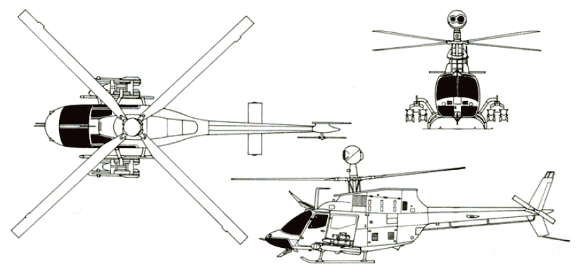
The qualification programme was completed by June 1984 and operational tests were conducted at Yuma and Edwards in February 1985 and completed by March of the same year. The Model 406 / OH-58D incorporated a new power-plant, advanced avionics and systems as well as extended armament capabilities. Fitted with the new four-blade composite rotors developed by Bell and a mast-mounted sight, the powerplant was a 650shp Allison 250-C30R (T703-AD-700) turboshaft driving a four-blade soft-in-plane rotor, in place of the 420shp Allison T63-A-720 turboshaft driving the classic two-blade rotor of the OH-58C. The OH-58D, as it was officially designated, was equipped with a McDonnell Douglas/Northrop mast-mounted sight (MMS) capable of operating in day/night and limited visibility and with a Honeywell Sperry cockpit control and display subsystem. The MMS brings together a lot of sophisticated technology. It is a combination of television camera, thermal imaging sensor, boresight system and laser range finder/ designator. Automatically, the system focuses and tracks the area and points targets. This system provides commanders with a survivable real time combat information, command and control, reconnaissance, security, aerial observation and target acquisition/designation system to operate with attack helicopters, air-cavalry and field artillery units during day, night and reduced visibility. The MMS enhances survivability by allowing the crew to accomplish its mission while hovering behind trees and hilltops. By day, the MMS provides long-range target acquisition with television in a 2deg by 8deg field of view, and at night with thermal imaging in a 3deg by 10deg field of view. It also provides laser designation at stand-off ranges for Hellfire, M172 Copperhead and other Army and Air Force laser guided munitions (LGM). Armament of the OH-58D includes four FIM-92A Stinger air-to-air missiles, or four Hellfire air-to-surface missiles, or two rocket pods, or two 12.7mm machine-gun pods, mounted on outriggers on the cabin sides. Qualification tests for these armaments were conducted during November and December 1987. Under the AHIP programme, 578 were expected to be procured over the 1985-91 period at an estimated cost of $2.000 million. An initial batch of 171 OH-58Ds had been funded during FY88, in five lots (16, 44, 39, 36 and 36 aircraft). A further thirty-six aircraft have been requested in FY89. In 1987, deliveries totalled eighty-seven OH-58Ds among which several were of the armed version. Responding to the Army’s desire to field an initial armed helicopter, Bell modified fifteen OH-58Ds to the attack configuration known as Kiowa Warrior or simply Warrior. By July 1987, sixty-four were on the US Army inventory and the first shipment to units stationed in Europe began on 11 June, 1987, when twelve OH-58Ds were loaded on board a single Lockheed C-5A Galaxy. Deliveries of the armed version began during the spring of 1988 to the 18th Airborne Corps Brigade at Fort Bragg. The Warriors were shipped to the Persian Gulf where they were stationed to protect the vital sea lanes for the world’s oil supply. Because of the success of the Persian Gulf operation, the Secretary of the Army ordered that 243 OH-58Ds be reconfigured to the armed Warrior version. Eighty-one of these aircraft will also be equipped as the Multi-purpose Light Helicopter (MPLH), capable of carrying troops externally, litter patients or cargo on a sling. First operational deployment of the US Army OH-58Ds occurred during operation ‘Desert Storm’ when aircraft were deployed by the Aviation Battalion of the 101st Airborne Division and the 82nd Aviation Brigade of the 82nd Airborne Division. In May 1984 Bell developed the Model 406CS (Combat Scout). This increased the capability of the OH-58D and provided a quick change weapons package. Designed as a force multiplyer, the 406CS can accept any of the roof-mounted sights in production or under development, with growth provisions for laser target designation, FLIR and video thermal tracker. Bell is also under contract with the US Government for an all-composite airframe program (ACAP) which will lead to expanded use of composite materials for all Bell helicopters, including future scout helicopters. The power-plant fitted to the 406CS is the Allison 250-C30 turboshaft developing 650shp with built-in particle separation system fitted to a 510shp transmission with elastomeric vibration isolation, fail-safe four-point mounting and a thirty minute run dry capability. The first OH-58D(I) retrofit contract awarded was in January 1992. The first 117 conversions were at Amarillo, Texas, then onwards Fort Worth The US Army initially planned to modify 592 OH-58A to OH-58D, reduced to 477; reduced again to 207, but Congressionally mandated re-orders increased the total to 398 (excluding five prototypes) by 1996 from new goal of 507. Taiwan ordered 12 OH-58Ds in February 1992, plus 14 options, subsequently converted to firm orders. Deliveries started in July 1993. The programme unit cost in 1993 was US$7.46 million. Production switched to the Kiowa Warrior from the 202nd aircraft and production was completed in 2000.
The OH-58D features a four-blade Bell soft in plane rotor with carbon composites yoke, elastomeric bearings and composites blades. Transmission rating: Kiowa 339kW continuous; Kiowa Warrior 410kW continuous. Main rotor 395 rpm; tail rotor 2,381 rpm. McDonnell Douglas/Northrop mast-mounted sight containing TV and IR optics and laser designator/ranger; Honeywell integrated control of mission functions, navigation, communications, systems and maintenance functions based on large electronic primary displays for pilot and observer/gunner; hands-on cyclic and collective controls for all combat functions; airborne target handover system in all OH-58Ds operates air-to-air as well as air-to-ground using digital frequency-hopping; system indicates location and armament state of other helicopters; some OH-58Ds have real-time video downlink capable of relaying of US Army and Air Force aircraft to headquarters 40km away or, via satellite, to remote locations. Fully powered controls, including tail rotor, with four-way trim and trim release; Stability and Control Augmentation System (SCAS) using AHRS gyro signals; automatic bob-up and return to hover mode; Doppler blind hover guidance mode; co-pilot/observer’s cyclic stick can be disconnected from controls and locked centrally. The basic OH-58 structure reinforced; armament cross-tube fixed above rear cabin floor; avionics occupy rear cabin area, baggage area and nose compartment. Powered by one Allison 250-C30R (T703-Ad-700) turboshaft, (C30R/3 with improved diffuser in Kiowa Warrior) with an intermediate power rating of 485kW at S/L, ISA, FADEC. Transmission rating: Kiowa 339kW continuous; Kiowa Warrior 410kW continuous. One self-sealing crash-resistant fuel cell, capacity 424 litres located aft of the cabin area. Refuelling point on starboard side of fuselage. Oil capacity 5.7 litres. ARMAMENT: Four Stinger air-to-air or Hellfire air-to-surface missiles, or two seven-round 70mm in rocket pods, or one 12.7mm machine gun, mounted on outriggers on cabin sides; port side only for gun.
Saudi Arabia’s have 15 Bell 406 Combat Scouts with roof-mounted sights. The stealth version of the Kiowa Warrior first flew on 6 August 1990 and the US Army’s 1/17th Cavalry flies them with a laser-proof windscreen and more pointed nose.
VERSIONS OH-58D (I) Kiowa Warrior: Armed version, to which all planned OH-58Ds are being modified; integrated weapons pylons, uprated transmission and engine, lateral CG limits increased, raised gross weight, EMV protection of avionics bays, localised strengthening, RWR, IR jammer, video recorder, SINCGARS radios, laser warning receiver and tilting vertical fin, armament same as Prime Chance, integrated avionics and lightened structure. “Prime Chance” is fifteen special armed OH-58Ds modified from September 1987 under Operation Prime Chance for use against Iranian high-speed boats in Gulf; delivery started after 98 days, in December 1987; firing clearance for Stinger, Hellfire, 0.50 in gun and seven-tube rocket pods completed in seven days. Further conversion for development trials. “MultiPurpose Light Helicopter” (MPLH) involved further modification of Kiowa Warrior; features include squatting landing gear, quick-folding rotor blades, horizontal stabiliser and tilting fin to allow helicopter to be transported in cargo aircraft and flown to cover 10 minutes after unloading from C-130. Later additions include cargo hook for up to 907kg (2,000 lb) slung load and fittings for external carriage of six outward-facing troop seats or two stretchers. All Kiowa Warriors have MPLH capability. OH-58X Light Utility Variant: Contender for anticipated US Army requirement; fourth development OH-58D (69-16322) modified in 1992 with partial stealth features (including chisel nose); concept subsequently discarded.
In late 1989, overall production by Bell of members of the Model 206 family was considerably in excess of 7,000. Agusta, in Italy, has also produced JetRangers and LongRangers under licence from Bell, these being generally similar to their American counterparts.
TH-67 Creek
In 1993 the US Army took delivery of Bell 206B-3 training helicopters, designated TH-67 Creek (Bell designation TH-206), selected in March 1993 as the US Army NTH (New Training Helicopter) choice to replace UH-1 at pilot training school, Fort Rucker, Alabama (223 Aviation Regiment at Cairns AAF and 212 Aviation Regiment at Lowe AHP). Instructor and pupil sat in the front seats. The US Army initial NTH contract was for US$84.9 million. Powered by Rolls-Royce (formerly Allison) 250-C20JN engine, the first batch included nine cockpit procedures trainers outfitted by Frasca International; three configurations: VFR, IFR, and VFR with IFR provision. TH-67 features also include dual controls, crashworthy seats, five-point seat restraints, heavy-duty battery, particle separator, bleed air heater, heavy-duty skid shoes and enlarged instrument panel. IFR version additionally possesses force trim system, auxiliary electrical system and is FAA certified for dual pilot operation. The US Army initial order was for 102 in IFR configuration, and a second batch of 35 VFR helicopters were ordered February 1994. Deliveries began on 15 October 1993 with N67001 and N67014 (all TH-67s have civilian registrations). 45 aircraft (and six procedures trainer) were delivered in time for the first training course to open on 5 May 1994. Initial orders were for 137 TH-67s and nine cockpit procedures trainers; all delivered by late 1995. Additional orders were placed on behalf of the Taiwanese Army, which received 30 TH-67s in 1997-99. Deliveries in 1999 included six to the Bulgarian Air Force. A further 50 were ordered for US Army for delivery between September 2001 and November 2003.
Over 7,750 JetRangers produced by Bell and licensees, including 4,400 Bell 206Bs and 2,200 military OH-58 series; and 900 in Italy. Bell Canada delivered 28 206Bs in 1999; 14 in both 2000 and 2001; and 20 in 2002 (including 10 TH-67s).
Variation: Trident Helicopters 206 L Gemini ST Industrias Cardoen Ltda C206L-III
Specifications:
Bell 206A Engine: 1 x Allison 250-C18A, 317 shp Baggage capacity: 250 lb / 115 kg Ext sling load: 1200 lb / 545 kg Seats: 5
Bell 206B – Engine: 400 shp
Bell 206B JetRanger II Engine: Allison 250-C20, 400 hp Main rotor dia: 33 ft 4 in / 10.16 m Fuselage length: 31 ft 2 in / 9.50 m Empty weight: 1455 lb / 660 kg MTOW: 3200 lb / 1451 kg Equipped useful load: 1613 lb Payload max fuel: 1119 lb Disc loading: 3.7 lb/sq.ft Pwr loading: 8 lb/hp Max cruise SL: 118 kt / 136 mph / 219 kph Max ROC SL: 260 fpm / 384 m/min Range max fuel/payload SL: 299 nm / 345 mi / 555 km Range max fuel/payload 5000 ft/1525m: 337 nm / 388 mi / 624 km Range max fuel/ cruise: 225 nm/1.9 hr Range max fuel / range: 262 nm/ 2.2 hr Service ceiling: 13,500 ft Max range cruise: 122 kt HIGE: 11,300 ft HOGE: 5800 ft Seats: 5 Cabin length: 7 ft 0 in / 2.13 m Cabin width max: 4 ft 2 in / 1.27 m Cabin heiht max: 4 ft 3 in / 1.28 m Baggage volume: 16 cu.ft / 0.45 cu.m Max sling load: 1500 lb Fuel cap: 494 lb
206 JetRanger III Engine: Allison 250-C20B, 313-kW / 420 shp, flat-rated to 236kW (317 shp) TBO: 3500 hr Main rotor: 10.16m (33ft 4in) Main rotor disc area: 81.1sq.m / 837 sq.ft Seats: 5 Length, rotors turning 11.82m (38ft 9.5 in) Height 2.91 m (9ft 6.5 in) Max ramp weight: 3200 lb Max takeoff weight: 3200 lb / 1451 kg Standard empty weight: 1616 lb / 730kg Max useful load: 1584 lb Max landing weight: 3200 lb Max sling load: 1500 lb Disc loading: 3.7 lbs/sq.ft Power loading: 7.6 lbs/hp Max usable fuel: 517 lb Max rate of climb: 1260 fpm Service ceiling: 4115 m / 13,5000 ft Hover in ground effect: 12,800 ft Hover out of ground effect: 8800 ft Max speed: 120 kt Normal cruise @ 3000 ft: 118 kt Maximum cruising speed: 216 km/h (134 mph) at 1525m (5,000 ft) Fuel flow @ normal cruise: 187 pph Endurance @ normal cruise: 2.6 hr Range with maximum fuel and payload at 1525m (5,000ft) 608 km (378 miles) External cargo hook capacity: 680kg
Bell 206B-3 Jet Ranger III Engine : Allison 250-C20J, 414 shp / 313 kW Length : 31.168 ft / 9.5 m Height: 9.547 ft / 2.91 m Rotor diameter : 33.333 ft / 10.16 m No. Blades: 2 Fuselage length: 9.5 m Max take off weight : 3199.5 lb / 1451.0 kg Weight empty : 1636.1 lb / 742.0 kg Payload: 696 kg Fuel cap: 345 lt Max. speed : 121 kts / 225 km/h Max cruising speed : 117 kts / 216 km/h Initial climb rate : 1259.84 ft/min / 6.4 m/s Service ceiling : 13501 ft / 4115 m HIGE: 3900 m / 12,800 ft HOGE: 2680 m / 8,800 ft Range : 675 km Crew: 2 Pax: 3
Bell 206L LongRanger Engine: Allison 250 C20B, 420 shp. TBO: 1500 hrs. Main rotor dia: 37 ft. Length: 33 ft. 3 in. Height: 9 ft. 6 in. Disc loading: 3.7 lbs./sq. ft Power loading: 9.5 lbs./hp Max TO wt: 4000 lb Empty wt: 2010 lb Equipped useful load: 1932 lb Payload max fuel: 1295 lb Fuel capacity: 98 USG/588 lb Rate of climb: 1,490 fpm Service ceiling: 12,900 ft VNE: 130 knots Max cruise: 113 kt Economy cruise: 106 knots Range @ max cruise (45 min res, std tanks): 201 nm Range @ economy cruise (no res): 341 nm Duration @ max cruise (no res): 2.6 hr Hovering in ground effect: 7,300 ft Hovering out of ground effect: 2,200 ft Baggage area: 15 cu.ft Seats: 7 Max sling load: 2000 lb
Bell 206L-1 LongRanger II Engine: Allison 250-C28B, 373kW / 500 shp TBO: 1500 hr Main rotor: 37 ft / 11.28m Seats: 6/7 Length: 42.7 ft / 12.46m Height: 10.5 ft Max ramp weight: 4150 lb Max takeoff weight: 4150 lbs / 1837kg Standard empty weight: 2202 lb Max useful load: 1948 lb Max landing weight: 4150 lb Max sling load: 2000 lb Disc loading: 3.9 lbs/sq.ft. Power loading: 8.3 lbs/hp Max usable fuel: 666 lb Max rate of climb: 1320 fpm Service ceiling: 19,500 ft Hover in ground effect: 12,400 ft Hover out of ground effect: 5000 ft Max speed: 115 kt Normal cruise @ 3000 ft: 115 kt Fuel flow @ normal cruise: 228 pph Endurance @ normal cruise: 2.7 hr Range: 620km
Bell 206L-3 Engine: Allison 250-C30P, 650 hp
Bell 206L-4 LongRanger IV Engine: One 485kW / 650 shp Rolls-Royce 250-C30P turboshaft (max continuous 415kW) Transmission take-off rating: 365kW Transmission continuous rating: 276kW Optional transmission rating: 340kW Rotor dia: 11.28 m Main rotor rpm: 394 MTOW: 2020 kg Payload: 974 kg Useful load: 974 kg Max speed: 130 kt Max cruise: 115 kt Max range: 675 km HIGE (@MAUW): 10,000 ft HOGE (@MAUW): 6600 ft Service ceiling: 10,000 ft Total usable fuel: 419 lt Double doors width: 1.55m Cargo hook capacity: 907kg Crew: 2 Pax: 5 Seats: 7
OH 58 Kiowa Rotor dia: 35 ft 4 in (10.77 m) Max speed: 138 mph (222 km/h)
OH 58A Kiowa Engine: one 317 shp Allison T63 A 700 turboshaft Length: 32.28ft (9.84m) Width: 35.33ft (10.77m) Height: 9.55ft (2.91m) Maximum Speed: 122mph (196kmh; 106kts) Maximum Range: 298miles (480km) Rate-of-Climb: 1,780ft/min (543m/min) Service Ceiling: 18,999ft (5,791m) Accommodation: 1 + 4 Empty Weight: 1,583lbs (718kg) Maximum Take-Off Weight: 2,998lbs (1,360kg) Seats: 2
OH-58D Engine: 1 x Allison 250-C30R rated at 485kW / 650 shp Main rotor diameter: 10.67m No. Blades: 4 Length with rotors turning: 15.85m Fuselage length: 10.48m Height: 3.93m MTOW: 2041 kg Payload: 719 kg Empty weight: 1380kg Max speed: 230km/h Cruising speed: 204km/h Ceiling: 3660+ m HIGE: 4270 m HOGE: 3260 m ROC: 219 m/min Range: 495km Main rotor rpm: 395 Tail rotor rpm: 2,381 rpm Fuel cap: 345 lt Crew: 2 Pax: 3
TH-67 Creek Engine: 1 x Allison 250-C20J Instant pwr: 315 kW MTOW: 1450 kg Payload: 709 kg Max speed: 130 kts Max range: 675 km HIGE: 12,800 ft Crew: 2 Pax: 3
406CS Engine: Allison 250-C30 Sling load: 680 kg
TexasRanger Engine: 1 x Allison 250 Installed pwr: 375 kW Rotor dia: 11.3 m No. Blades: 2 Empty wt: 1050 kg MTOW: 1927 kg Payload: 877 kg Max speed: 210 kph ROC: 445 m/min Ceiling: 4845 m HIGE (1880kg): 4900 m HOGE (1880kg): 1585 m Fuel cap: 415 lt Range: 600 km Crew: 1 Pax: 6
206LT TwinRanger Engine: 2 x Allison 250-C20R Instant pwr: 335 kW Rotor dia: 11.28 m MTOW: 2020 kg Payload: 908 kg Max speed: 130 kts Max cruise: 110 kts Max range: 480 km HIGE (@MAUW): 10,000 ft HOGE: 6900 ft Service ceiling: 20,000 ft Crew: 2 Pax: 5 Seats: 7
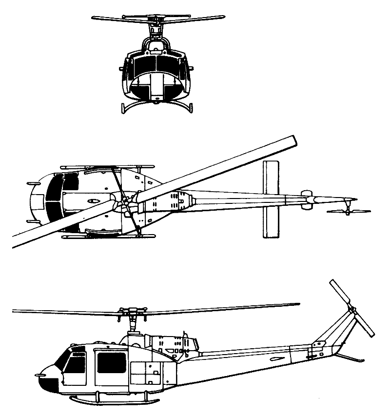
In 1960 the US Army launched a design competition for a new aircraft which it certified as a Light Observation Helicopter (LOH). The specification called for four seats, a 181-kg (400-lb) payload and cruising speed of around 193 km/h (120mph). Design proposals were put forward by 12 US helicopter manufacturers from whom Bell, HilIer and Hughes were each contracted to build five prototypes for competitive evaluation. From the tests which followed, the Hughes HO-6 (later OH-6A) was selected for production as the US Army’s LOH. The Bell aircraft featured two-bladed main and tail rotors, skid landing gear, and a conventional pod-and-boom layout with a protruding ‘bubble’ nose. Manufacturer’s flight test programme with the Bell OH 4A light observation helicopter (first flown on 8 December 1962) was completed in August 1963, and during this programme a number of modifications were introduced. These include the addition of a vertical fin above the tailboom to improve static and dynamic directional stability; the lengthening of the cabin nose by ten inches to reduce drag and improve balance; the moving forward of the horizontal stabiliser by thirty inches to improve longitudinal stability, and the addition of external stiffeners at the junction of the underside of the fuselage and the tailboom. Machine gun and grenade launcher armament have been tested on the ground and in the air.
The four-place OH-4A in the Army’s LOH competition covered a 700 mile course in 4 hr 27 min for an average speed of 159 mph, powered by a 250 hp T-63 Allison turbine.
The JetRanger was fundamentally the same as the OH-4A (formerly HO-4) prototypes, except for fuselage modifications to provide seat¬ing for five.
After losing the competition the company built a new prototype which it designated as the Model 206A JetRanger.
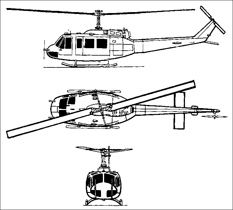
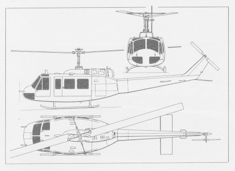
In 1955 the US Army initiated a design competition to speed the procurement of a new helicopter suitable for casualty evacuation, instrument training, and general utility duties. In June 1955 the US Army selected the Bell Helicopter Company’s proposal, this having the company designation Bell Model 204. The new helicopter was known initially to the US Army as the H-40, changed to HU-1 when it entered service, and given the name Iroquois. It was also the first of the ‘Hueys’, a nickname evolved from the HU-1 designation which, in 1962, was altered to UH-1 under the tri-service rationalisation scheme.
The US Army’s first order was for three prototypes for testing, under the designation XH-40, the type having the H-40 designation allocated to it at that time to identify it in the USAF helicopter category. The first of these prototypes made its first flight on 22 October 1956, and these were used by Bell for test and development. Just before the first flight, six examples of the pre-production YH-40 were ordered, all being delivered by August 1958. The YH-40 evaluation aircraft were essentially the same as the XH-40 prototypes but had their cabin space extended a full 12-inches. One remained with Bell, but the remainder were distributed one each to Eglin AFB and Edwards AFB, and three to Fort Rucker, for trials. Duly ordered into production, nine of the definitive pre-production HU-1A were delivered on 30 June 1959, and were followed into service by 74 production examples, of which 14 went to the Army Aviation School at San Diego. The latter aircraft had dual controls and were used as instrument trainers. First major use overseas was with the 55th Aviation Company in Korea, and HU-1As were among the first US Army helicopters to operate in Vietnam. The 57th Medical Detachment would be the first in Vietnam beginning in March 1962. In all, over 3,300 UH-1 Hueys were lost in Vietnam, from a total of over 5,000 introduced to the region.
The Model 204 had a stabilising bar above and at right angles to the two blades of the main rotor, and also had a small elevator surfaces attached to the rear fuselage. Tubular skid-type landing gear was ideal for utility operations and accommodation was provided for a crew of two and six passengers or two stretchers. Powerplant consisted of a 522kW Avco Lycoming T53-L-1A turboshaft, and this made the Model 204 the first turbine-powered aircraft, rotary- or fixed-wing, to be ordered by the US Army.
In this HU-1 a series of seven speed, distance and rate of climb records was set up in July 1960. The best speed was 158.05 mph and the time to climb to 9843 ft was 3 min 22.4 sec.
Production totalled 182 HU-1A / UH-1A’s. These were followed by four YUH-1B prototypes leading up to the UH-1B production model, of which more than 700 were built, essentially being “improved” A-models. Early production HU-1B having the 716kW Avco Lycoming T53-L-5 engine, and late production models the 820kW T53-L-11 engine. Other improvements in the HU-1B included redesigned main rotor blades, and an enlarged cabin to accommodate a crew of two, plus seven passengers or three stretchers.
In 1963 the USAF first ordered the Iroquois. Twenty-five were ordered for delivery beginning March 1064 to be used by SAC to transport personnel and supplies to remote Minuteman missile sites. The USAF UH-1F have 48 ft rotor, four feet longer than UH-1D, and 1250 hp GE T58/8B engine instead of Lycoming T53/9 of 1100 hp. They can lift one ton payload or pilot and 10 passengers. The DoD had transferred responsibility for military Iroquois procurement from the USAF to the Army. About 70 UH-1’s were being produced each month for US military services.
In the autumn of 1965 the UH-1B was superseded in production by the UH-1C, which had an improved ‘door-hinge’ rotor with wide-chord blades, this new main rotor conferring some increase in speed and improved manoeuvrability. 767 were built.
A few UH-1As operating in Vietnam were equipped with rocket packs and two 7.62mm machine-guns for use in a close-support role, and the success of these resulted in many UH-1Bs serving in a similar capacity, armed mainly with four side-mounted 7.62mm machine-guns, or two similarly-mounted packs, each containing 24 rockets. Other military versions of the Model 204 include the UH-1E for the US Marine Corps (generally similar to the UH-1B, but equipped with a personnel hoist, rotor brake and special avionics). The first being delivered to the Marine Air Group 26 on 21 February 1964, and from October 1965 Bell’s new ‘door-hinge’ rotor being fitted to production aircraft; the UH-1F for the USAF, generally similar to the UH-1B but with a 962kW General Electric T58-GE-3 turboshaft, increased-diameter rotor, and able to accommodate a pilot and 10 passengers; a similar TH-1F training version of the above, for the USAF; the HH-1K SAR version for the US Navy, similar to the UH-1E but with 1044kW T53-L-13 engine; TH-1L and UH-1L training and utility versions respectively of the UH-1E with T53-L-13 engine; and three of the UH-1M with night sensor equipment for evaluation by the US Army.
By the fall of 1962, the Army’s first true gunships began to accompany Army troops carrying helicopters on their airmobile missions. These were UH-1A, Hueys, that were equipped essentially in the field with side mounted .30 calibre machine guns, pods for carrying 2.75in rockets, and door gunners equipped with machine guns. Because of the success of the UH-1As, production of the UH-1B started and this became the Army’s standard gunship and the first armoured helicopter to appear in sizable quantities. The UH-1B was essentially the same as the A model, but did have a more powerful engine and better armament. Starting in 1963, some of the Army Huey gunships rode shotgun for Maron air assault missions. Meanwhile the Marine Corps was beginning to fully realise the potential of the helicopter for the unique fighting conditions found in Vietnam. USMC doctrine called for attack aircraft, naval gunfire, and artillery fire to secure a safe landing zone for helicopter borne assault troops. This was difficult in Vietnam where the bad guys were intermingled with the good guys. Air strikes with almost surgical precision were needed to suppress the enemy without doing harm to the civilian population. The Marines, especially those experienced in the SHUFLY operations, recognised that the armed helicopter was the weapon to do the job. It could fly low and slow and even hover while firing its weapons. The first armed Hueys were delivered to the Marines in February 1964, and a year later they went to work in Vietnam. The Marine’s gunship was essentially identical to the Army’s UH-1B except the UH-1E had its external gun fixed in a forward firing position. The Army version had a flexible gun system. This difference in gun mounting led to different deployment tactics for the Army and Marine Corps, the Army’s being more desirable. To overcome the deficiency in flexibility, later versions of the UH-1E were equipped with a turret below the nose of the helicopter which held two M-60 machine guns. The Marine Hueys also had a rotor brake that was necessary for amphibious operations. For on the flight deck it was necessary to stop the rotors immediately. The Marines purchased a total of 270 UH-1Es which turned out to be very good gunships, perhaps even too good a gunship. The Marines originally intended to use the UH-1E for armed observation and reconnaissance, command and control, liaison, and airborne forward air controllers. But because of the frequent lack of availability of fixed wing close support aircraft, the Huey’s effectiveness, and its ability to fly under conditions that kept fixed wing fighters on the ground, almost two-thirds of the UH-1E missions were as armed gunships to support ground troops. Thus, there was a shortage of Hueys for the role for which they were originally intended.
The Model 204B was built in small numbers by Bell, for civil use and military export. Generally similar to the UH-1B, these were of 10-seat capacity, had the larger-diameter rotors of the UH-1F, and the T53-L-11 engine. Model 204Bs and UH-1s have been built by Fuji in Japan, under sub-licence from Mitsubishi, and in 1967 this company introduced the Fuji-Bell 204B-2, which differs from the Model 204B by having a more powerful engine and a tractor tail rotor.
The Australian Navy bought six UH-1Bs in 1964 to replace Bristol Sycamore for air-sea rescue.
YUH-1B
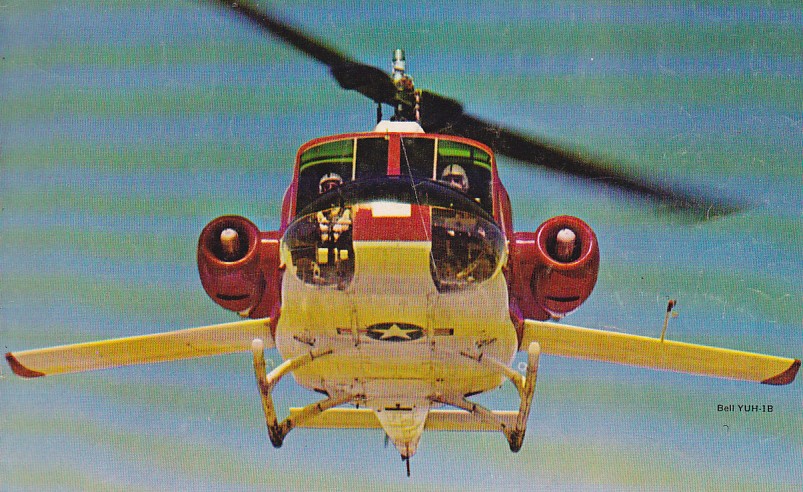
As part of the US Army’s high-speed helicopter research program, in 1964 a Bell YUH-1B was modified with adjustable stub wings to unload the main rotor. Powered by a 1100 hp T53 and two 630 lb thrust turbojets mounted along the fuselage, it was able to reach 222 mph.
The Italian company Costruzione Aeronautiche Giovanni Agusta built large numbers of the Model 204 under the designation Agusta AB.204 for many customers, some of them (including the Swedish navy version) being powered by a Rolls Royce Gnome turboshaft in place of the usual T53. Production switched from the AB.204 in 1966 to the larger multi role AB.205.
UH-1H
The commercial Model 204B features a two-blade all-metal semi-rigid main rotor with interchangeable blades. Usual Bell stabilising bar above and at right angles to main rotor blades. Underslung feathering axis hub. Two-blade all-metal tail rotor of honeycomb construction. Blades do not fold. Shaft-drive to both main and tail rotors. Main rotor rpm 295 to 324 (294 to 317 in UH-1F only). The main blades built up of extruded aluminium spars and laminates. Blade chord 53.3cm. All-metal tail rotor blades. The fuselage is a conventional all-metal semi-monocoque structure. A small synchronised elevator on rear fuselage is connected to the cyclic control to increase allowable CG travel.
Bell 205A-1
The landing gear is a tubular skid type, with lock-on ground handling wheels available. The 204B is powered by one 820kW Lycoming T5309A turboshaft engine mounted above fuselage aft of cabin. Two fuel tanks on CG, immediately aft of cabin, have a total capacity 916 litres. The cabin holds a crew of two side by side, with dual controls. Standard model has bench seats for eight passengers, three abreast in centre row and five abreast in rear row. Optional layouts include individual chairs with tip-up seats or special interiors to customer’s requirements, with optional settee, cabinet, writing table and glass-panelled dividing wall between crew and passenger compartments. Two doors on each side, front one hinged to open forward, rear one sliding aft. Compartment for 182kg of baggage. Passenger seats removable to provide 3.96cu.m of accessible cargo space for loads of up to 1,360kg weight. Forced air ventilation system. Standard equipment includes hydraulic power boost on cyclic, collective and tail rotor flying controls. Optional equipment includes full all-weather flight instrumentation, multichannel select VHF transceivers, visual omni-range and ILS course indicator with heading and glide slope presentation, ADF, VHF marker beacon receivers, Sperry C-4 navigation compass, Lear VGI 5 in all-attitude flight indicator, and external sling for 1,820kg of freight.
In early 1960 Bell proposed an improved version of the Model 204 design with a longer fuselage, plus additional cabin space resulting from relocation of the fuel cells, thus providing accommodation for a pilot and 14 troops, or space for six stretchers, or up to 1814kg of freight. In July 1960, therefore, the US Army awarded Bell a contract for the supply of seven of these new helicopters for service tests, these having the US Army designation YUH-1D and being identified by the manufacturer as the Bell Model 205. The first of these flew on 16 August 1961, and following successful flight trials was ordered into production for the US Army, the first UH-1D being delivered to the 11th Air Assault Division at Fort Benning, Georgia, on 9 August 1963. The powerplant of these initial aircraft was the (1100shp) 820kW Avco Lycoming T53-L-11 turboshaft, driving a 14.63m rotor, and the standard fuel storage of 832 litres could be supplemented by two internal auxiliary fuel tanks to give a maximum overload capacity of 1968 litres of fuel. Accommodation provided for a pilot and 14 troops, or six stretchers and a medical attendant, or 1815kg of cargo. Large-scale production of the UH-1D followed for the US Army, as well as for the armed forces of other nations, and 352 were built under licence by Dornier in West Germany for service with the German army and air force.
The USMC UH-1E was based on the UH-1B and UH-1C models. 192 of this type were built.
The USAF UH-1F were based on the UH-1B and UH-1C models, using of General Electric T-58-GE-3 turboshaft engines of 1,325shp. 120 total examples of these Hueys were produced.
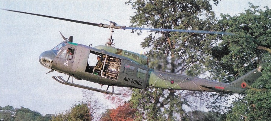
The UH-1D was followed into production, by the more or less identical UH-1H which differed, however, in the use of the more powerful (1400shp) 1044kW Avco Lycoming T53-L-13 turboshaft engine. Delivery of the UH-1 H to the US Army began in September 1967, and this variant proved to be the final production version. The UH-1H was built extensively for the US Army, nine were supplied to the RNZAF, and under the terms of licence agreement which was negotiated in 1969, the Republic of China (Taiwan) produced a total of 118 of these aircraft for service with the Nationalist Chinese army. Variants of the UH-1H include the CH-118 (originally CUH-1H) built by Bell for the Canadian Armed Force’s Mobile Command, with the first of 10 being delivered on 6 March 1968; and the HH-1H local base rescue helicopter of which 30 were ordered for the USAF on 4 November 1970, deliveries being completed during 1973. By 1976 1242 UH-1H had been built.
UH-1H NZ3801 RNZAF No.3 Sqn
The UH-1D/H was employed extensively on a very wide range of duties in South East Asia, and was regarded by many as the workhorse helicopter par excellence in Vietnam. In particular, the type played a major role in special warfare operations in Laos, Cambodia, and in some of the remote areas of South Vietnam, and USAF historians have commented that in this latter theatre of operations nearly all battlefield casualties were evacuated by UH-1 helicopters.
Specifically the military UH-1H features a two-blade semi-rigid main rotor. Stabilising bar above and at right angles to main rotor blades. Underslung feathering axis head. Two-blade all-metal tail rotor. Shaft drive to both main and tail rotor. Transmission rating 820kW. Main rotor rpm 294 to 324.
A small synchronised elevator on rear fuselage is connected to the cyclic control to increase allowable CG travel. The interchangeable main blades are built up of extruded aluminium spars and laminates. Tail rotor blades of honeycomb construction. Blades do not fold. The fuselage is a conventional all-metal semi-monocoque structure.
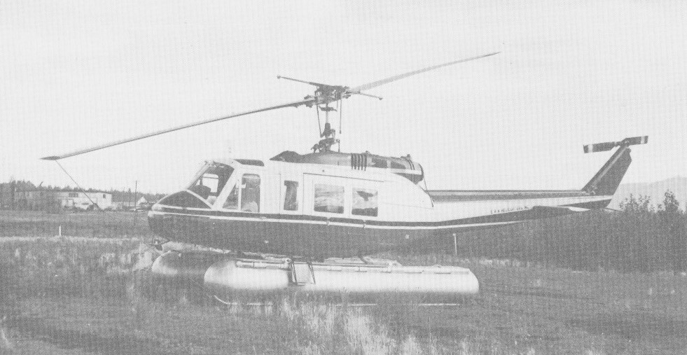
The landing gear is tubular skid type. Lock-on ground handling wheels and inflated nylon float bags available. Powered by one 1,044kW Textron Lycoming T53-L-13 turboshaft, mounted aft of the transmission on top of the fuselage and enclosed in cowlings. Five interconnected rubber fuel cells, total capacity 844 litres, of which 799 litres are usable. Overload fuel capacity of 1,935 litres usable, obtained by installation of kit comprising two 568 litre internal auxiliary fuel tanks interconnected with the basic fuel system.
The UH-1H seats a pilot and 11 to 14 troops, or six litters and a medical attendant, or 1,759kg of freight. Crew doors open forward and are jettisonable. Two doors on each side of cargo compartment; front door is hinged to open forward and is removable, rear door slides aft. Forced air ventilation system.
Since that time, a small number of UH-1Hs have been selected to fulfill an electronic counter-measures role under the designation EH-1H, and examples with advanced systems were being delivered from 1981. Under the US Army’s Stand-Off Target Acquisition System (SOTAS) programme, four UH-1Hs were modified for evaluation. Their role was to obtain radar data of battlefield movements, relaying them to commanders on the ground and providing real-time information on the tactical situation.
Bell also produces a commercial version of the UH-1H under the designation Model 205A-1. It is powered by a 1044kW (1250shp) Avco Lycoming T5313B turboshaft, derated to 932kW. Normal fuel capacity of the Model 205A-1 is 814 litres, with an optional fuel capacity of 1495 litres. Because it is intended for a wide range of users, special attention has been given to interior design to permit quick conversion for air freight, ambulance, executive, flying crane and search roles. External load capacity in the flying crane role is 2268kg. Maximum accommodation is for a pilot and 14 passengers.
5,435 UH-1H were built and featured an improved Lycoming T-53-L-13B turboshaft engine of 1,400shp.
The USN utilized the purpose-built HH-1K (based on the Bell Model 204) for Search and Rescue duties. The UH-1M was a dedicated gunship model fitted with the Lycoming T-53-L-13 engine of 1,400shp.
Built by Agusta under license from Bell, the AB.205 is a direct counterpart of the UH-1H Iroquois (Model 205) military helicopter. Production switched from the AB.204 in 1966 to the larger multi role AB.205. In its basic form, the AB.205 is similar to the US Army’s UH-1D and UH-1H, but can be configured for specialist roles such as SAR with a door-mounted rescue hoist. The AB.205 is equipped for all-weather operation in its military utility role, and can be fitted with protective armor as well as any of several arma-mentkits. In l969Agusta started licensed produc¬tion of the Model 205A-1 civil version as the AB.205A-1 and, like its American counterpart, this is powered by the 1,400-shp (l,044-kW) T53 13B civil version of the military turboshaft derated, in this application, to 1,250 shp (932 kW). Production of the AB.205A-1 totalled 290 helicopters.
In Japan the Fuji-Bell Model 205A-1 is available. The UH-1J, built by Fuji of Japan, is a Bell 205B powered by an up-rated 800 shp Kawasaki built Textron Lycoming T53 turboshaft. Versions have also been built under licence in West Germany (Dornier). The UH-1D may be up-graded to a UH-1H by replacing the engine with the T53-L-13.
A US Army Request for Proposal for composite main rotor blades for the UH-1H was issued on 16 November 1981. The army’s schedule called for a qualified blade to be ready for production after 32 months. Procurement of 6,000 blades was anticipated in 1985-89, at a cost of US$20,000 or less per blade in FY81. Bell tendered a joint proposal with Boeing, and this team was awarded a US$19 million development contract during 1982 by the US Army Aviation Research and Development Command. Bell designed the composite blade for the UH-1H, but both companies fabricated test blades and supported laboratory and flight testing to ensure compliance with army requirements. The composite rotor blades provide a 6% improvement in the UH-1H’s hovering capability and a 5 to 8 per cent reduction in fuel flow in forward flight. Bell provided manufacturing tools and fixtures and transferred specific manufacturing knowledge to Boeing, so that both companies were equally capable and qualified to manufacture production blades, for which contracts are expected to exceed US$100 million. The first flight of the composite rotor blades on a UH-1H took place in early 1985. Production deliveries began in January 1988.
Bell 204 Variants: XH-40: Three prototypes, the first of which flew in 1956.
YH-40: Six service test models.
UH-1: Nine preproduction models.
UH-1A Iroquois: initial six-seater production version powered by one Lycoming T53-L-1A turbo-shaft engine, derated to 770shp. Deliveries began to the US Army on 30 June 1959 and were completed March 1961. Thirteen modified to carry 70mm rockets and two 7.62mm machine-guns for service in Vietnam with the Utility tactical Transport Helicopter Company. A total of 14 was delivered for use as helicopter instrument trainers with dual controls and a device for simulated instrument instruction.
UH-1B Iroquois: development of the UH-1A powered initially by one 960shp T53-L-5 turboshaft engine. Subsequent deliveries with 1100shp Lycoming T53-L-11 engine. Crew of two plus seven troops or three stretchers and two sitting casualties. Alternatively 1360kg of freight. Rotor diameter 13.41m. Normal fuel capacity 625 litres; overload capacity 1,250 litres. For armed support missions could be equipped with rocket pack and electrically controlled machine-guns. Delivered from March 1961. This version was superseded by the UH-1C on the Bell assembly line, but production continued by Fuji in Japan in order to fulfil an order of 89 UH-1Bs for the JGSDF.
UH-1C: In September 1965, Bell introduced its Model 540 ‘door hinge’ rotor, with blades of increased 69mm chord, on this developed version of the UH-1B, offering some increase in speed and a substantial increase in manoeuvrability through resistance to blade stall. Through reduced vibration and stress levels, the 540 rotor eliminated previous limitations on maximum level flight speed. T53-L-11 turboshaft, accommodation and armament as for UH-1B. Normal fuel capacity 916 litres; overload 2,241 litres. Superseded UH-1B in production for US Army, but itself superseded by AH-1G.
Bell 211 HueyTug: It was announced on 3 September 1968 that a UH-1C had been retrofitted with a 2,125kW Lycoming T55-L-7C turboshaft and 15.24m ‘door-hinge’ rotor as the prototype of a new flying crane version able to lift a 3 ton external payload. Associated modifications, all of which could be applied retrospectively to existing UH-1s, include substitution of a 1,491kW transmission and larger tail rotor, reinforcement of the airframe and fitment of a larger tailboom, and use of a stability control and augmentation system instead of the normal stabiliser bar.
UH-1E: In March 1962, Bell won a design competition for an assault support helicopter for the US Marine Corps, to replace Cessna O-1B/C fixed-wing aircraft and Kaman OH-43D helicopters. Designated UH-1E, this version is generally similar to the UH-1B/C, but has a personnel hoist, rotor brake and marine electronics. The 540 rotor and increased fuel capacity (as UH-1C) were introduced in 1965.
UH-1F: Following a design competition, it was announced in June 1963 that an initial batch of 25 UH-1F helicopters, based on the UH-1B were to be built for the USAF in 1963-64, and many more later, for missile site support duties. Each has a 948kW General Electric T58-GE-3 turboshaft (derated to 820kW), a 14.63m rotor, normal fuel capacity of 945 litres and overload capacity of 1,552 litres. This version can handle up to 1,815kg of cargo at missile site silos, or carry a pilot and 10 passengers. The first UH-1F flew 20 February 1964. Subsequent contracts for a further 121 aircraft were completed in 1967. First delivery to an operational unit was made to the 4486th Test Squadron at Eglin AFB in September 1964. This model was used for classified psychological warfare missions in Vietnam.
TH-1F Iroquois: training version of UH-1F for USAF.
HH-1K Iroquois: SAR version for US Navy. Twenty-seven ordered and delivered in 1970. Powered by T53-L-13 engine (derated to 820kW), the aircraft has the UH-1E airframe, and revised avionics.
TH-1L Iroquois: training version for US Navy, similar to UH-1E. Powered by T53-L-13 turboshaft, derated to 1100shp. Improved electronics. Contract for 45 received 16 May 1968; the first of these was delivered to the US Navy at Pensacola, Florida, 26 November 1969.
UH-1L: Utility version of TH-1L for US Navy. Eight ordered, and delivered during 1969.
UH-1M: US Army version fitted with Hughes Aircraft Iroquois night fighter and night tracker (Infant) system to detect and acquire ground targets under low ambient lighting conditions, two sensors mounted on nose of cabin serve a low-light level TV system with three cockpit displays and a direct-view system using an image intensifier at cockpit/gunner’s station. Three UH-1Ms deployed with hunter-killer helicopter groups in Vietnam in early 1970 to evaluate system.
RH-2: one UH-1A used as flying laboratory for new instrument and control systems. Installations included an electronic control system and high-resolution radar in a large fairing above the flight deck, enabling the pilot to detect obstacles ahead of the aircraft in bad visibility.
Model 204B: Commercial and military export version of UH-1B, with 10 seats, 820kW T5311A turboshaft and 14.63m rotor. Tailboom incorporates a 0.99cu.m baggage compartment, cabin doors with jettisonable emergency exits, passenger steps on each side of cabin, improved outside lights, commercial radio equipment, fire detection and extinguishing systems. First flight 8 March 1962; received FAA certification 4 April 1963.
UH-1P Iroquois: Similar to UH-1F but used for special missions.
Agusta-Bell 204B: utility helicopter, similar to Iroquois, produced under licence in Italy by Agusta from 1961 to 1974 and sold to military and civil customers. By end of 1973 about 250 delivered, including the AB 204AS version for the Italian and Spanish navies, armed with two Mk.44 homing torpedoes or AS.12 air-to-surface missiles depending on anti-submarine search and attack or anti-fast surface vessel role.
Bell 205 Variants:
CH-118: Similar to UH-1H, for Mobile Command, Canadian Forces. First of 10 delivered on 6 March 1968. Originally designated CUH-1H.
EH-1H: Electronic countermeasures configuration, with the Quick Fix I airborne communications interception, emitter locating and jamming system, including an AN/APR-39(V)2 radar warning receiver, XM130 chaff/flare dispenser and AN/ALQ-144 infra-red jammer. The FY81 budget added US$5.1 million to convert initial Quick Fix IA systems in the EH-1H to Phase IB configuration, plus survivability equipment to protect the aircraft against known and postulated threats, including hot metal/plume suppression. However, the Quick Fix mission has been taken over by the much larger Sikorsky EH-60A version of the Black Hawk utility transport helicopter.
HH-1H: It was announced on 4 November 1970 that a fixed price contract worth more than US$9.5 million had been received from the USAF for 30 HH-1H aircraft (generally similar to the UH-1H) for use as local base rescue helicopters. Deliveries were completed during 1973.
UH-1D: This US Army version of the Model 205 Iroquois has an 820kW Lycoming T53-L-11 turboshaft, 14.63m rotor, normal fuel capacity of 832 litres and overload capacity of 1,968 litres. Relocation of the fuel cells increased cabin space to 6.23m3, providing sufficient room for a pilot and 12 troops, or six litters and a medical attendant, or 1,815kg of freight. A contract for a service test batch of seven YUH-1Ds was announced in July 1960 and was followed by further very large production orders from the US Army and from many other nations of the non-Communist world. First YUH-1D flew on 16 August 1961 and delivery to US Army field units began on 9 August 1963. The UH-1D was superseded in production for the US Army by the UH-1H, but 352 UH-1Ds were built subsequently under licence in Germany for the German Army and Air Force. Prime contractor was Dornier.
UH-1H: Following replacement of the original T53-L-11 turboshaft by the 1,044kW T53-L-13, the version of the Model 205 for the US Army was designated UH-1H. Deliveries of an initial series of 319 aircraft for the US Army began in September 1967. Another 914 ordered subsequently in several batches, with delivery extending into 1976. Under a licensing agreement concluded in 1969, the Republic of China produced UH-1Hs for the Nationalist Chinese Army, with much of the manufacturing and assembly process carried out at Taichung, Taiwan. Total procurement 118.
UH-1V: Approximately 220 UH-1Hs converted by US Army as a medevac version. Avionics and equipment in this version include a radio altimeter, AEL AN/ARN-124 DME, glide slope and rescue hoist. The 7,000th Model 205/205A helicopter was completed in 1973.
Model 205A-1: Civil and export designation of UH-1H. Also built in Italy by Agusta, Japan by Fuji and Taiwan by AIDC. First flight 22 March 1967; FAA certification 25 October 1968. A total of 332 produced by Bell at Fort Worth, Texas between 1968 and 1980.
AB 205A: Agusta-built version of the Bell 205 UH-1D. Also built in Germany by Dornier.
AB 205A-1: Agusta-built Bell Model 205A-1 (UH-1H).
Specifications:
XH-40 Engine: 1 x Lycoming T53, 620/640 shp. MTOW: 5800 lb / 2631 kg Useful load: 1000 lb / 454 kg
Model 204 Engine: 522kW Avco Lycoming T53-L-1A turboshaft Vne: 120 kt Crew: 2 Accommodation: six passengers or two stretchers
Model 204B Similar to the UH-1B Engine: 820kW T53-11A turboshaft Rotor diameter: 14.63m Vne: 120 kt Baggage compartment: 0.99cu.m Seats: 10
Model 204B Engine: one 820kW Lycoming T53-09A turboshaft engine Main rotor: two-blade all-metal semi-rigid Rotor dia: 48 ft / 14.63m Main rotor rpm: 295 to 324 Tail rotor: Two-blade all-metal Fuel capacity: 916 litres. Vne: 120 kt Crew: two side by side Passengers: eight Baggage Compartment: 182kg Freight: 1,360kg External sling capacity: 1,820kg
Bell 205A-1 Engine: Lycoming T5313A turboshaft, 1400shp derated to 1250shp. Main rotor diameter: 48 ft 0 in / 14.63 m Fselage length: 41 ft 6 in / 12.65 m Empty weight, equipped: 5197 lb / 2357 kg Normal TO weight: 9500 lb / 4309 kg MTOW, external load: 10,500 lb / 4763 kg Max cruise SL normal TOW: 110 kt / 127 mph / 204 kph Max ROC SL normal TOW: 1680 fpm / 512 m/min Service ceiling normal TOW: 14,700 ft / 4480 m Range, SL, max cruise, normal TOW: 270 nm / 311 mi / 500 km Range 8000ft/ 2440m max cruise, no res, normal TOW: 298 nm / 344 mi / 553 km Cargo caacty: 248 cu.ft / 7.02 cu.m External load: 5000 lb / 2268 kg Seats: 15
Bell 205A-1 Commercial version of the UH-1H Engine: 1044kW (1250shp) Avco Lycoming T5313B turboshaft, derated to 932kW. Seats: 15 Disc loading: 5.25 lb/sq.ft Pwr loading: 6.8 lb/hp Max TO wt: 9500 lb Empty wt: 5199 lb Equipped useful load: 4266 lb Payload max fuel: 1645 lb Range max fuel/ cruise: 437 nm/ 4 hr Range max fuel / range: 482 nm/ 4.6 hr Service ceiling: 14,500 ft Max cruise: 110 kt Vne: 120 kt Max range cruise: 106 kt ROC: 1680 fpm HIGE: 10,400 ft HOGE: 6000 ft Max sling load: 5000 lb / 2268kg Normal fuel capacity: 814 litres Optional fuel capacity: 1495 litres. Maximum accommodation: Pilot + 14 passengers.
CUH-1H / CH-118 Similar to UH-1H Vne: 120 kt
HH-1H: Generally similar to the UH-1H Vne: 120 kt
HH-1K Similar to the UH-1E Engine: 1044kW T53-L-13 (derated to 820kW) Vne: 120 kt
UH-1D Engine: 1 x Lycoming T53-L-11, 1100 shp / 820kW Max speed: 124 kt Std fuel cap: 832 lt (+560 lt aux) Maximum overload fuel capacity: 1968 lt Range std fuel: 370 km Rotor dia: 48 ft (14.63m) Length: 41.503 ft / 12.65 m Height: 14.6 ft / 4.45 m Vne: 120 kt HIGE: 13,600 ft Service ceiling : 21982 ft / 6700 m Empty wt: 2363 kg MTOW: 9500 lb / 4309.0 kg Range: 281 nm / 520 km Crew: 2 Accommodation: 14 troops, or six stretchers and a medical attendant Cargo capacity: 1815kg
UH-1E Generally similar to the UH-1B/C The 540 rotor and increased fuel capacity (as UH-1C) were introduced in 1965. Vne: 120 kt
UH-1F Similar to the UH-1B Engine: 962kW General Electric T58-GE-3 turboshaft Vne: 120 kt Accommodation: Pilot and 10 passengers
UH-1F Based on UH-1B Engine: General Electric T58-GE-3 turboshaft 1272 shp / 948kW (derated to 820kW) Rotor dia: 48 ft / 14.63m Main rotor rpm: 294 to 317 Vne: 120 kt Normal fuel capacity: 945 lt Overload capacity: 1,552 lt Cargo capacity: 1,815kg Passenger capacity; 10
Model 205 / UH-IH Engine: 1 x 1044-kW (1,400-shp) Avco Lycoming T53-L-13 turboshaft Maximum speed 204km/h (127 mph) Cruise: 110 kts ROC: 488 m/min Hovering ceiling in ground effect 4145m (13,600ft) Service ceiling 3840m (12,600ft) Vne: 120 kt Fuel capacity: 844 litres Usable fuel: 799 litres Overload fuel capacity: 1,935 litres usable Range with maximum fuel at sea level 511 km (318 miles) Empty equipped weight: 2363 kg (5,210 lb) Mission take-off weight: 4100kg (9,039 lb) Maximum take-off weight: 4309 kg (9,500 lb) Max underslung load: 1045kg Freight capacity: 1,759kg Main rotor diameter: 14.63m (48ft) Main rotor: two-blade semi-rigid Transmission rating 820kW. Main rotor rpm: 294 to 324. Tail rotor diameter: 2.59m (8ft 6 in) Tail rotor: Two-blade all-metal Length, rotors turning: 17.62m (57ft 9.75in) Height, tail rotor turning: 4.43m (14ft 5½ in) Width: 2.8m Main rotor disc area 168.06 sq.m (1,809 sq.ft) Passengers: 9 passengers or 5 troops (full pack) or 7 troops (light) or six litters and a medical attendant
UH-1J Engine: Lycoming T53, 1800 shp. Vne: 120 kt
Fuji UH-1J Similar to Bell 205B Engine: 1800 shp Kawasaki built Textron Lycoming T53 turboshaft. Vne: 120 kt
UH-1L Similar to the UH-1E Engine: T53-L-13 engine Vne: 120 kt
UH-1P Iroquois Similar to UH-1F Vne: 120 kt
UH-1V Converted UH-1H Vne: 120 kt
YUH-1B Engines: Lycoming T-53, 1100 hp / 2 x thrust toubojets, 630 lb Max speed: 333 mph
AB 204AS Armament: two Mk.44 homing torpedoes or AS.12 air-to-surface missiles
AB 205A / Bell 205 UH-1D
Fuji/Bell Model 204B-2 Engine: 1 x Avco Lycoming T53-13B turboshaft, 1044kW (1,400-shp) derated to 1,250 shp (932 kW). Main rotor diameter: 14.63m / 48 ft Main rotor disc area 168.1 sq.m (1,809.5sq.ft) Fuselage length: 12.31 m (40ft 4.75 in) Height: 3.77m (12 ft 4.5 in) Maximum take-off 3856 kg (8,500 lb) Empty weight: 2177 kg (4,8001b) Max speed: 204km/h (127 mph) Hovering ceiling, IGE: 4635m (15,200ft) Service ceiling: 5790m (19,000ft) Range at sea level: 383km (238 miles)
AB.205A-1 / UH-1H Engine: one 1,400-shp (l,044-kW) Lycoming T53-L-13 turboshaft derated to 1,100 shp (820 kW) Maximum speed: 138 mph (222 kph) at sea level Initial climb rate: 1,680 ft (512 m) per minute Service ceiling: 15,010 ft (4,575 m) Range: 360 miles (580 km) Empty weight: 4,800 lb (2,177 kg) Maximum take-off weight: 9,500 lb (4,309 kg) Main rotor diameter: 48 ft 3.25 in (14.71 m) Length overall, rotors turning: 57 ft 0.75 in (17.39 m) Height: 14 ft 8.5 in (4.48 m) Main rotor disc area: 1,829.36 sq ft (169.95 sq.m) Payload: 14 troops, or six litters and one attendant, or freight.
One Bell Model 47G was fitted experimentally with a Turbomeca Artouste turbine built under license by Continental as the Model 200-T51T-3; it delivered 425shp. As the XH-13F, it was built at the beginning of 1955 to test some components for the Bell 204.
Bell’s first turbine helicopter, the XH-13F, first flew on October 20, 1954, with test pilot Bill Quinlan at the controls. Project engineer for this joint Army/USAF research program was J. R. “Bob” Duppstadt.
The engine weighed so little that it had to be mounted behind the helicopter’s fuel tanks and rotor mast for weight-and-balance reasons.
Pleased with the prototype during its Phase I (factory) testing, Quinlan called the XH-13F the “smoothest Model 47 ever built”. At the start of April 1955, the prototype was handed over to USAF Major Jones P. Seigler and First Lieutenant Donald A. Wooley. The two officers, attached to Edwards Air Force Base in California, conducted the Phase II test program at Fort Worth to ensure good coordination with Bell.
At the end of the 1940s, it became apparent that the helicopters in the Navy’s inventory were not of the size to accomplish anti-submarine warfare (ASW) missions and in 1950 the US Navy launched an industrywide competition for a new helicopter to be designed specifically for the ASW role. Bell’s only twin-rotor helicopter, the HSL-1 was the largest US helicopter of the day and was the first helicopter designed from the outset for the submarine hunter/killer role with the Fairchild Petrel air-to-underwater missile. In June 1941, Bell won this competition in June 1950, and was awarded a contract calling for the building of three prototypes of its Model 61, to be designated XHSL-1 (BuNos 129133/129135). The two rotors were of the basic Bell two blades and automatic stabilising bar. The fore and aft rotors were interconnected and could be folded for carrier operations but the HSL was too large even with its rotors folded, to fit on the elevators of the aircraft carriers. The Model 61 was powered by a single 2.400hp Pratt & Whitney R-2800-50 engine installed in the centre fuselage and driving a transmission shaft to the front pylon, and total fuel capacity was 425 US gal providing a flight endurance of nearly four hours. Armament was intended to include air-to-surface missiles such as the Fairchild AUM-2 Petrel, as well as a dipping ASDIC. The HSL-1 was equipped with a Bell-developed autopilot which permitted motionless hovering for long periods. For the development and production, the Bell Helicopter Division was moved from Buffalo to Fort Worth.
Powered by a 2400hp Pratt & Whitney R-2800-50 engine, the first of three prototypes flew on 4 March 1953. After the vibration had been cured, carrier tests were made aboard the escort carrier USS Kula Gulf (CVE-108) in March 1955. Even if the HSL performed well in the air, its large size, even with rotor blades folded, was not compatible with the carrier’s elevator. Even worse, was its very high level of noise while in stationary flight and this limited the sonar operator’s capability of identifying contacts. Due to these shortcomings the first production contract calling for seventy-eight HSL-1s, including eighteen machines under MAP destined for Britain’s Fleet Air Arm, was cut back to fifty (BuNo 129154/129168, 129843/129877) in July 1955. A follow-on contract for sixteen more (BuNo 140414/140429) was cancelled. The Navy ordered the Sikorsky HSS-1 “Sea Bat” instead. Deliveries to Squadron HU-1 began in January 1957. Production models differed from the prototypes in having stabilising fins at the rear of the fuselage. The HSL-1 programme was not a complete failure because the Bell helicopter demonstrated interesting capabilities in the mine-sweeping role. Six HSL-1s were modified to do this and were operated by the Navy Mine Defense Laboratory in Panama City (Florida), until the end of 1960. The remaining aircraft were used for training or as spares.
HSL-1
The HO4S, which the HSL-1 had been intended to replace, remained in service until the appearance of the HSS-1 antisubmarine version of the Sikorsky S-58.
A civil variant, the D-116, and two derivatives of the HSL-1 were considered under design numbers D-216 and D-238 but they remained as projects.
No HSL-1 seems to have survived.
HSL-1
HSL-1 Engine: 1 x Pratt & Whitney R-2800-50, 1415kW Rotor diameter: 15.70m Fuselage length: 11.90m Height: 4.40m Width (rotors folded): 3.5m Loaded weight: 12020kg Maximum speed: 185km/h Cruising speed: 155km/h Range: 563km Fuel capacity: 425 US gal Warload: 800 kg Payload: 1814 kg
By February 1946 the USAAF issued a to specification for a liaison and observation aircraft. This called for a two-seat, single main rotor type of about 1360kg gross weight and to be powered by a supercharged engine of approximately 260hp. G & A Aircraft Co (Firestone) of Willow Grove, Pennsylvania, won first place and was awarded a contract for three examples of its 100hp Continental A100 powered XR-14-GA (s/n 46-527/529) which were never built. Bell, with its Model 54 proposal, won only second place in this design competition. But at that time, some AAF personnel advocated a contract with Bell and in May 1946 action was initiated for the building and development of three examples of the Model 54 under the designation XR-15-BE (to be redesignated XH-15-BE in 1948). The formal contract was signed a few weeks later. The XR-15 was to be developed both for the Air Force and Army Ground Forces. The Model 54 was an all-metal four-seat helicopter using the same basic rotor system employed in other Bell models, featuring a two-blade rotor with stabilising bar. Power was provided by one 275hp Continental XO-47-5 engine located at the bottom of the rear cabin. Accommodation was provided for a crew of two seated side-by-side in a largely glazed cabin. It had a semi-monocoque fuselage reinforced with stiffeners and fitted with a horizontal stabiliser, and a tricycle (later quadricycle) non-retractable undercarriage. The two-bladed anti-torque rotor was fitted on the starboard side. The aircraft were initially designated XR-15, but this had been changed to XH-15 by the time the first example made its maiden flight in March 1948. Three aircraft were built (s/n 46-530-532) and tested but no production contracts followed. Though funded by the Army Ground Forces (AGF) the XH-15 was evaluated almost exclusively by the Air Force, the latter service having taken control of several AGF aviation projects following the 1947 creation of the USAF. All three examples acquired were used by the Army as high altitude research vehicles until development of the Model 54 came to a halt at the end of 1950. They were stricken from the inventory in the early 1950s. No XH-15 has survived.
In 1946, Bell developed a new general utility helicopter of larger dimensions than the Model 47, as the Model 42, and a military version, the Model 48. The general configuration was a two-blade rotor with stabilising bar, three-wheel non-retractable undercarriage and five-seat cabin with car-like windscreen and doors. The engine was a 540hp Pratt & Whitney R-1340-AN-1 Wasp radial mounted horizontally in the rear fuselage with radiator air intake on top. Alternative equipment included flotation gear for water operation (which was tested on aircraft s/n 46-215), rescue hatch and hoist, litters and life rafts. The USAAF ordered two prototypes of a military derivative, the Model 48, designated XR-12-BE (s/n 46-214/215) as well as a static test airframe. A first production batch of thirty-four examples (R-12A-BE, s/n 47-491/524) was ordered but never built. This order was cancelled in 1947. Meanwhile, the USAAF had ordered a prototype of an enlarged variant, designated XR-12B-BE (s/n 46-216), able to carry up to ten people. This prototype, known as the Model 48A, was followed by a batch of ten similar service trials YR-12B-BE (s/n 46-217/226) with the more powerful 600hp Pratt & Whitney R-1340-5 5 Wasp. The YH-12B was different in shape and the undercarriage had four wheels (wheel base 3.30m; wheel track 2.13m). The wider cabin had separate doors for the crew and passengers and the nose was nearly all-glazed. Horizontal stabilisers were fitted each side of the tail boom. The anti-torque rotor was now located on the port side of the tail-boom end. At the time, the approximate cost of the YR-12, less government-furnished equipment, was estimated at $175,000. Initial deliveries of the YR-12 were scheduled for the summer of 1946. However, Bell was faced with serious engineering difficulties with the prototype. Serious blade weaving and rotor governor trouble were encountered in the main rotor system. In April 1946, Bell accepted the assistance of the Propeller Laboratory at Wright Field to overcome these problems. In May 1946, the USAAF considered that the YR-12 ‘was going to require considerable development and time delay before it was a successful ship’ and procurement of the heavier Sikorsky S-51 was then considered. Delivery of the first YR-12 was in September 1946. Flight tests went smoothly but no production batches of the H-12 were ordered. In 1948, the Bell Model 48 and 48A were respectively re-designated XH-12-BE, XH-12B-BE and YH-12B-BE. They were used for a variety of test programmes before being withdrawn from use. None of them is known to have survived.