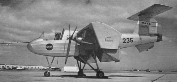
Developed with possible Army operational applications in view, the Ryan VZ 11 uses a totally different concept to obtain VTOL performance. The outcome of several years’ work on lift fans by General Electric Corporation, the VZ 11 derives its vertical lift from two ducted fans, one in each wing.
Unlike other ducted fans, above the General Electric version is powered by the jet exhaust from a turbojet engine which is directed on to turbine blades at the tips of the fan blades.
The VZ 11 layout has two 2,658 lb.s.t. General Electric J85 GE 5 turbojets in the fuselage, fed by a dorsal intake over the two seat cabin. For vertical operations, the fans are powered, together with a third fan in the nose which provides a small lift increment but is primarily for pitch control. For roll control, the thrust developed by the wing fans can be varied differentially by means of ‘butterfly’ doors over the inlets. Louvres under the outlets provide yaw control.
Once the VZ 11 is airborne, the louvres are moved to deflect the fan flow rearwards. This gives the aircraft a forward thrust component. As speed builds up the undercarriage is retracted. At about 120 knots, the wings provide sufficient lift to sustain flight and the exhaust flow from the two engines is then switched from the fans to direct propulsion nozzles. The butterfly doors and louvres close over the fan ducts and the aircraft continues as a conventional jet propelled type.
Two prototypes of the VZ 11 were ordered from Ryan in November 1961 as part of a U.S. Army research contract to investigate lift fans which was placed with General Electric. The designation was changed to VZ-5A in July 1962 and flight trials began in 1963. The XV-5 first flew in May 1964.
Republic Aviation joined GE and Ryan in XV-5A development and was directing flight tests at Edwards AFB in 1964. Republic would share in building additional prototypes if the craft met Army and DoD expectations.
XV-5A Engines: 2 x 1200kg General Electric J85-GE-5 Max take-off weight: 7690 kg / 16954 lb Empty weight: 5450 kg / 12015 lb Wingspan: 9.25 m / 30 ft 4 in Length: 13.75 m / 45 ft 1 in Height: 4.5 m / 15 ft 9 in Max. speed: 880 km/h / 547 mph Ceiling: 12200 m / 40050 ft Range: 1600 km / 994 miles
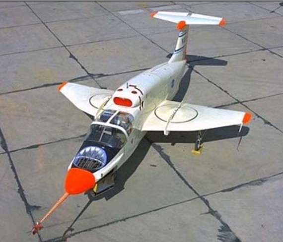
The X-13 was designed to explore the feasibility of building a pure-jet vertical takeoff and landing (VTOL) fighter aircraft. Secondary purposes included validating several Ryan designed VTOL control system concepts.
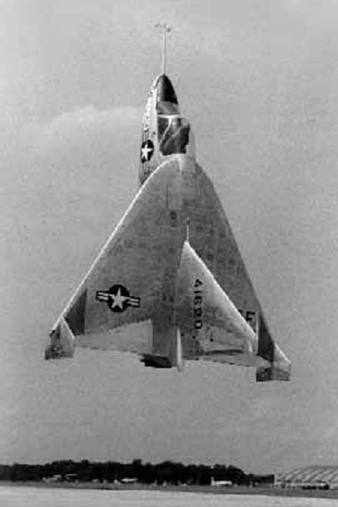
Ryan produced the X-13 Vertijet and XV-5 VTOL aircraft for the USAF. The X-13 was a ‘tail-sitter in the mould of the Convair XFY-1 and Lockheed XFV-1, though in this instance configured as a pure research type powered by a single 10,000-lb (4536-kg) Rolls-Royce Avon turbojet. The aeroplane first flew in conventional mode with temporary wheeled landing gear on 10 December 1955, and in ‘tail-sitter’ mode during May 1956.
The seat tilted forward 45 degrees to give the pilot a more comfortable position during vertical flight. Many early flights were made with no canopy. As first built, the X-13 had a huge fin, its height nearly as great as the wingspan. This was shortened during later testing.
The success and efficiency of the X-13 flight test program provided a significant amount of data to the designers of subsequent VTOL aircraft designs. The X-13s proved that vertical flight, on jet thrust alone, was both technically feasible and practical. The ease with which the aircraft routinely transitioned from vertical to horizontal attitude, and back again, left little question as to the flexibility and operational utility of such flight modes.
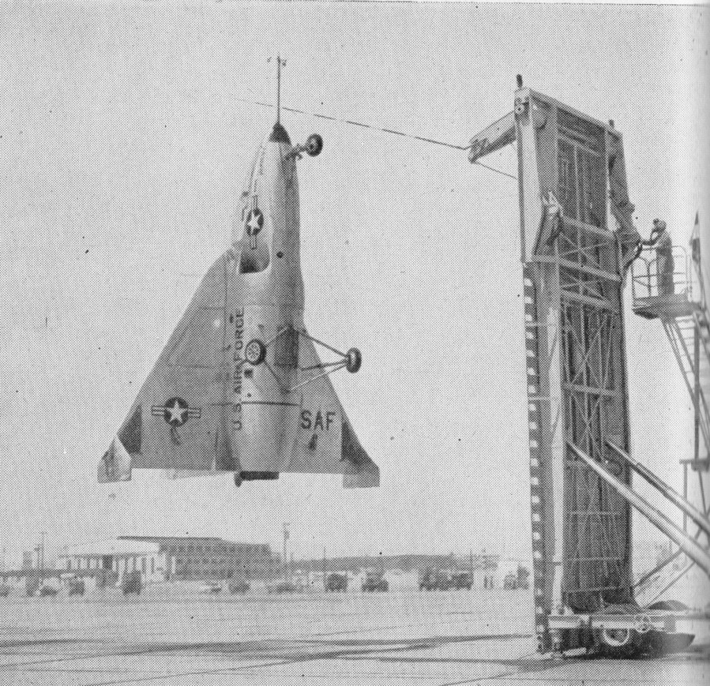
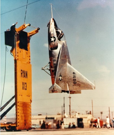
The delta-winged X-13 used a unique landing method, involving a special trailer, a hook and a striped pole. To land the pilot had to approach the trailer’s vertical base board without being able to see it. A pole marked with gradations protruded from the board and the pilot had to use this to judge his ‘altitude’ from the landing wire. In one demonstration at the Pentagon, the X-13 flew from its trailer, crossed the Potomac River, destroyed a rose garden with its thrust and landed in a net. Although this impressed the top brass, further funding was not forthcoming and the project petered out.
The last flight was made on 30 July 1957. Fastest Flight: 483 mph (approx) Highest Flight: 10,000 feet (approx)
Both X-13s survived their test program. The first aircraft is on loan from the National Air and Space Museum to the San Diego Aerospace Museum in California. The second aircraft is on display at the Air Force Museum in Dayton, Ohio.
Engine: 1 x 4540kg Rolls-Royce Avon RA.28-49 turbojet Max take-off weight: 3317 kg / 7313 lb Wingspan: 6.40 m / 21 ft 0 in Length: 7.13 m / 23 ft 5 in Height: 4.60 m / 15 ft 1 in Max. speed: 777 km/h / 483 mph
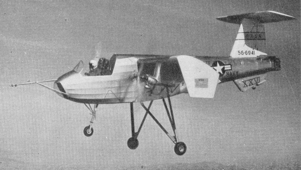
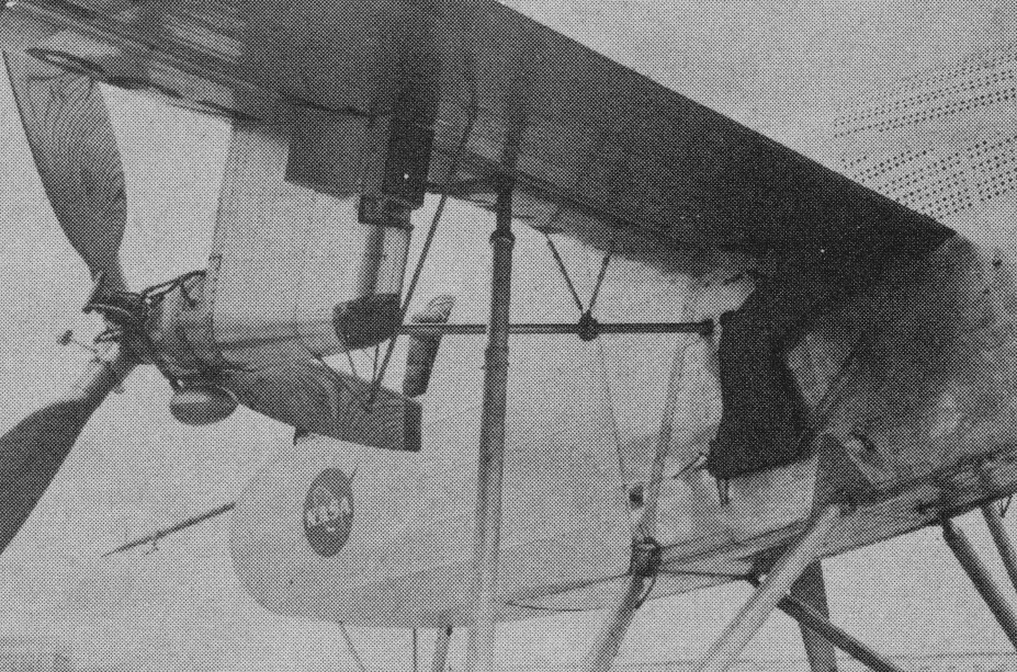
Ordered by the Army in 1956, the VZ 3 or Ryan Model 92 Vertiplane makes use of the deflected slipstream principle which was first proposed in the U.S. as early as 1921 by Dr. Albert F. Zahm. The principle consists of using a conventional wing and propellers for cruising flight and having large flaps on the wing trailing edge which, when extended, deflect the propeller slipstream down¬ward to obtain vertical lift.
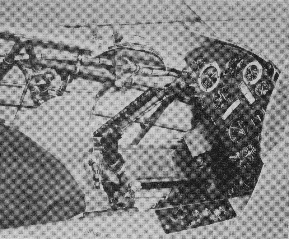
The VZ 3 is basically a high wing monoplane with a 1,000 hp Lycoming T53 L 1 turboshaft engine in the fuselage driving two 9 ft. diameter slow running propellers. The wing tips were turned down to prevent spanwise flow and power loss when the flaps were down. For control at low, speeds, engine exhaust was directed to a swivel nozzle at the end of the fuselage, giving pitch and yaw control; roll control came from differential pitch applied to the propellers.
Ryan test pilot Peter Girard made the first taxying trials of the VZ 3 (56 6941) on February 7th, 1958.
Subsequently, it spent three months in the full scale low speed wind tunnel at the N.A.S.A. Ames Laboratory at Moffet Field. At this stage it had a tail down undercarriage, but a nosewheel was added, as well as a large ventral fin, before the first flight was made on January 21st, 1959, at Moffet Field.
On the thirteenth test flight, on February 13th, 1959, the VZ 3 was damaged in a landing mishap caused by a malfunction in the propeller control system. Trials were resumed later in the summer and Ryan completed a test programme in which a speed range of 110 knots to 26 knots was covered, and flights were made up to 5,500 ft. For this second series of trials the cockpit canopy was removed.
In February 1960, after being handed over to NASA, the VZ 3 was almost completely de¬stroyed on a pilot familiarization flight. Operating outside the approved envelope for safe flight, it pitched up and completed most of a loop at 5,000 ft. The pilot ejected safely at 1,000 ft.
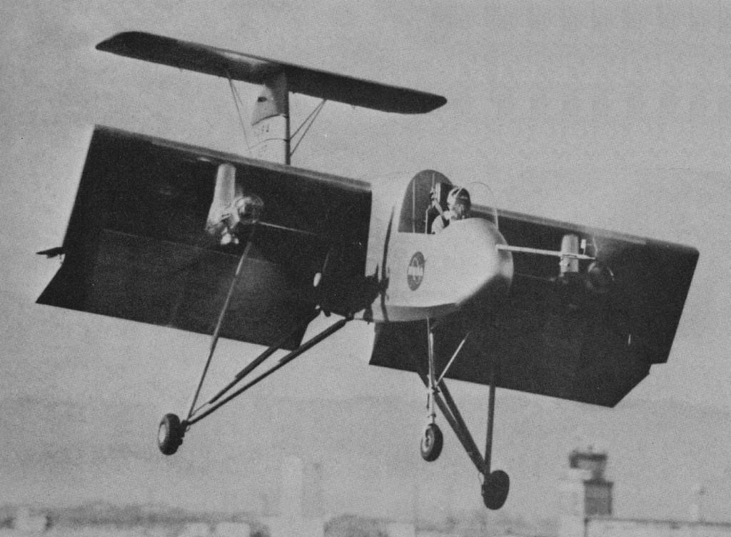
After it crashed in 1960 the VZ-3RY was rebuilt with lengthened nosewheel strut, 9 degree lower thrust axis and the LW-1 lightweight ejection seat. Utilising a deflected slipstream principle, the 785 shp Lycoming T53-L-1 turbine, located centrally in the fuselage, drives two wing-mounted Hartzell 3-bladed wood props whose slipstream covers the full wing span. For V/STOL and hover, double wing flaps are fully extended; for transition to horizontal flights, flaps are retracted as the plane picks up speed and the slipstream then flows horizontally.
70 degrees level flight with full flap, 29 mph
Conventional stick and rudder pedals controls actuate rudder, elevator, variable-incidence T-tailplane, and spoilers in the upper wing forward of the flaps, these replace the usual ailerons. Large wing tip end-plates provide structural support for the flaps and confine the slipstream.
Gas turbine tailpipe nozzles deflect Jetstream at right angles to eliminate forward thrust. Pitch and yaw control is achieved by shielding one side of the nozzle. For roll control ailerons actuate prop pitch control differentially when flaps are extended.
After a complete rebuild, the VZ 3 was returned to NASA in 1961 and pilots Fred Drinkwater and Bob Innis began a programme to investigate its low speed handling characteristics. Several modifications were made at this time, since when the VZ 3 has been contributing valuable data for the development of other VTOL aeroplanes.
Engine: 1 x 785 shp Lycoming T53-L-1 Props: 2 x Hartzell 3-bladed wood Span: 23 ft 5 in Length: 27 ft 8 in Height: 10 ft 8 in Gross weight: 2925 lb
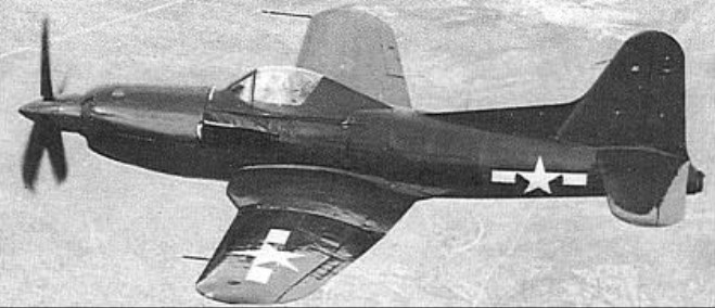
A major modification of the FR-1 Fireball, the Model 29 resulted from a Bureau of Aeronautics requirement for a single-seat fighter combining a turboprop with a turbojet. Assigned the designation XF2R-1 and later to become known unofficially as the “Dark Shark”, the single prototype utilised the fifteenth FR-1 production airframe and retained that fighter’s J31-GE-3 turbojet, mated with a General Electric XT31-GE-2 turboprop developing 1,700hp plus 227kg of residual thrust.
Although lacking the wing folding and the catapult and arrester gear standard on the FR-1, the XF2R-1 weighed 473kg more than its predecessor when it flew for the first time in November 1946. The XT31 drove a propeller with four square-tipped hollow-steel blades which could be fully feathered or reversed to zero blade angle extremely rapidly, the drag of the flatter blade angle serving as an effective air brake for landing. By comparison with the FR-1, the vertical tail surfaces of the XF2R-1 were enlarged to compensate for the lengthening forward to accommodate the turboprop, but the airframe of the later fighter was similar in most other respects. The XF2R-1 underwent extensive testing at Muroc Dry Lake, but no further development was undertaken.
Max take-off weight: 4990 kg / 11001 lb Wingspan: 12.80 m / 42 ft 0 in Length: 10.97 m / 36 ft 0 in Height: 4.27 m / 14 ft 0 in Wing area: 28.33 sq.m / 304.94 sq ft Max. speed: 800 km/h / 497 mph Ceiling: 11920 m / 39100 ft
Mahoney-Ryan Aircraft Corporation Ryan Aeronautical Corporation
Founded 1928 at St Louis, Missouri, as Mahoney-Ryan Aircraft Corporation, deriving from Ryan Airlines, which began operations on U.S. West Coast in 1922.
Ryan was in partnership with B.F. Mahoney. Conflict between the two led Ryan to sell out of the company that bore his name, only to see it become world famous less than a year later as the builder of Lindbergh’s Spirit of St. Louis, a larger descendant of the M 1.
In 1926 began manufacture of Ryan M-1 mailplane from which Charles Lindbergh’s transatlantic Ryan NYP Spirit of St Louis was developed in 1927. Commercial version of the latter, Ryan Brougham, was built in quantity.
Ryan merged with Detroit Aircraft Corporation in 1929, but DAC did not survive the slump in 1930-1931.
T. Claude Ryan formed Ryan Aeronautical Company in 1933-1934 and produced the S-T training monoplane, forerunner of a series of successful Ryan trainers. The S T became the Army’s basic trainer; his school won contracts to train thousands of Army pilots, and his subsidiary bases multiplied. During the war, his business grew from $1 million to $55 million.
The YO-51 Dragonfly of 1940 was observation monoplane built for the USAAC. A new fighter for the U.S. Navy in 1943 reflected a “belt and braces” outlook on the new gas turbine engine, having a mixed powerplant comprising a conventional piston engine and rear-fuselage jet. Known as the FR-1 Fireball, it was too late to see operational service in Second World War.
The end of the war came as a blow to Ryan, as it did to all airframe manu¬facturers whose lucrative contracts were abruptly cancelled. For a while, the company went into the lugubrious business of building metal coffins; then it took over the Navion from North American in 1947 and built the plane until the Korean War.
Ryan developed to a mid-1950s USAF contract the X-13 Vertijet, a delta-wing vertical-take-off jet with Rolls-Royce Avon engine. A flex-wing research aircraft was built in 1961, and the XV-5A lift-fan research aircraft followed in 1964. Development of the “fan-in-wing” VTOL principle continued with two prototype aircraft, later restyled XV-5B.
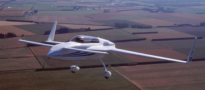
The same basic concept of the model 27 was retained in the Model 31 VariEze. The type was designed in 1974, and the construction of a prototype GRP two-place tandem design took Rutan just 10 weeks to complete. Rutan built two prototypes in succession; the second incorporated several major changes. When the larger O 200 engine was installed on the second prototype (the first had a VW), the additional torque produced an unpleasant wing heaviness under power. So Rutan added an electric trim tab on the right wing, rudder trim, a fuselage mounted drag brake, and a pair of small inboard spoilers on the rear wing roots that both quicken the roll response and eliminate the unwanted pitch. With a manually retractable nosewheel, its handling and approach qualities are now more or less conventional, with a bit more reliance on rudder for roll, and a bit less concern with keeping the ball centered, than we’re used to.
A lot of experimental work was necessary, but the VariEze is a radical departure from conventional methods in aerodynamic and structural design. An alteration was the replacement of the VariViggen’s electrically retracted tricycle landing gear arrangement by a tricycle arrangement with a mechanically retracted nose unit and fixed main units with glassfibre legs. The nose unit can be retracted on the ground, a feature that eases access to the cockpit, provides greater propeller clearance for manual starting, and removes the need for chocks. The complete airframe is made of unidirectional glassfibre over a foam core.
This sleek, fast, lightweight homebuilt is capable of achieving a top speed of 210 mph with Continental’s 100-hp engine. The unusual aircraft combines the use of a NASA GA (W)-1 airfoil with Whitcomb winglets and was actually the first aircraft to fly with the latter. The wing is a nonlaminar flow airfoil optimized for good lift and stall qualities. The ship’s low induced drag lets the pilot negotiate steep, 90-degree banks with strong spiral stability. First flew, in prototype form, in May 1975. In its refined form, with its retractable nose leg which had to be retracted to gain cabin entry, could cruise comfortably at 140 mph when propelled by 100 horsepower.
Rutan claimed that a VariEze could be built in 600 hours. By contrast, 2,000 to 3,000 hours had always been the average for completing a conventional homebuilt. Structural strength was provided by epoxy fiberglass skins and spars that were laid up over cores of light plastic foam. The wings consisted of several foam cores cut from blocks with an electrically heated wire and joined end to end. A chunk the shape of the box spar was cut out of the assembled wing core, and the spar webs laid up around it. Then the still wet spar core was reinserted in the wing core, the multilayer spar caps laid down, and the wing skins laid down over the whole works. One side of a wing was skinned and allowed to cure. Then the wing was flipped over and the other side laid up. Rather than conventional plans, Rutan put out an instruction book in which verbal instructions replaced blueprints, and the builder was led, step by step, from the beginning of the project to the end.
First offered to homebuilders in the summer of 1976, VariEze plans were bought by more than 2,000 prospective homebuilders within six months; and in that same period, the first buyer built airplanes were already flying.
In the meantime, several companies put portions of VariEze kits on the market.
By 1979, of the 3,000 buyers of plans, 1,800 have bought some sort of kit; about 100 VariEzes were flying, and hundreds more are near completion.
The hot wire cut polystyrene foam cores used for flying surfaces were easy to work with, though a few errors in the plans did lead to irritating minor discrepancies in final assembly. These were corrected piecemeal in Rutan’s frequent newsletter.
The VariEze’s performance is not a free lunch. You pay for it in somewhat peculiar handling qualities. The seating is comfortable but quite supine; that plus a narrow bubble canopy makes it difficult to turn your head. The pi¬lot, who sits in front and commands the only controls, can barely communicate with the passenger, even using simple ideas and loud shouts.
The pilot’s controls in the first of the two prototypes were uniquely simple: a small side stick on the right armrest was connected directly to movable surfaces on the canard to provide both pitch and roll control. There were no movable surfaces on the main wings. Rudder pedals controlled outward going rudders on each wingtip; pressed farther, they activated wheel brakes as well. A simpler, lighter control system could not be devised. But the plane was hard to fly; its glide was so flat and it floated so far in experienced hands that it required a 3,500 foot runway; roll response was liable to be nullified completely by a touch of the wrong rudder and apt to include a bit of unwanted pitch in the bargain.
By 1990 the Rutan design stable of VariEze, LongEze, Defiant and Solitaire were no longer offered for sale.
Engine: 1 x 100-hp (74.5kW) Continental 0-200-B Seats: two seated in tandem. Maximum cruising speed 195 mph (313 km/h) at optimum altitude Initial climb rate 1600 ft (487 m) per minute Range 850 miles (1368 km) Empty weight: 580 lb (263 kg) Maximum take-off 1050 lb (476 kg) Wingspan 22 ft 2.5 in (6.77 m) Length 14 ft 2 in (4.32 m) Wing area 53.6 sq.ft (4.98 sq.m) Canard foreplane area 13 sq.ft (1.21 sq.m) Fuel capaci¬ty 26 USG Takeoff run 900ft Landing roll 900ft Range 700miles
Engine: Lycoming O 235 Max speed: 180 kt at sea level ROC: 800 fpm Gross wt: 1,050 lb
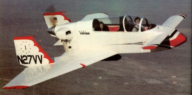
In 1968 Rutan began the design of his Model 27, which first flew on 27 February 1972 and then became the VariViggen canard lightplane for the homebuilder market. The VariViggen is a tandem two- or four-seat lightplane of canard layout with a cropped delta main wing, and the 150 hp (112 kW) of its Avco Lycoming 0-320-A2A flat-four piston engine provides a sea-level maximum speed of 163 mph (262 km/h) at a maximum take-off weight of 1700 lb (771 kg), together with a range of 400 miles (644 km) on 35 US gal (132 litres) of fuel. The VariViggen is an application of the low speed aerodynamics of the Viggen ca-nard arrangement, with various changes, to a general aviation purpose: a tandem two seat pusher with a 150 hp Lycoming engine and a fixed pitch wood propeller. It is an old proj¬ect; Rutan started developing the configura¬tion when he was still at Cal Poly. He tested models on a “car top wind tunnel” of his own invention, flew Styrofoam gliders and an 18¬percent scale, radio controlled model to in¬vestigate his design’s flying qualities and fi¬nally completed the full size prototype at Lan¬caster, California. It flew almost exactly as his scale tests had predicted it would.
Optimized for low-¬speed maneuverability, it is not a particularly fast airplane 130 knots cruise on 113 hp ¬and its climb performance is only just ade¬quate, because its low aspect ratio lifting sur¬faces produce a lot of drag at high lift coeffi¬cients. What makes the VariViggen unique is its low speed handling, in which it has little in common with conventional airplanes.
On the face of it, it appears that what makes the VariViggen a slow climber and mediocre cruiser is simply its short span. The canard, which is only eight feet across, car¬ries a quarter of the airplane’s weight while the main wing, carrying the rest, has a span of 19 feet. The aspect ratios of the fore and main-planes are 3.5 and three, respectively. The wing loading is 14.3 lb/sq.ft. and the power loading is 11.31 lb/hp. The weighted average of spans (weighted in proportion to surface loading) is only 16.25 ft. giving a linear span loading of more than 100 lb/ft.
The VariViggen is not stressed for aero¬batics in the RA’s limited definition of the term. The limit load factor is five. The air¬plane will roll nicely, Rutan says, but is too draggy for high G maneuvers like loops and is characteristically incapable of snapping or spinning.
Its cruising range is short: 326 nm, with no reserve on internal tankage. The cockpit is reasonably comforta¬ble (25 inches wide and amply long and high) and its noise level is moderate, at least partly thanks to the wooden structure and the placement of the engine and prop at the rear. There is a large baggage compartment be¬hind the back seat with a 180 pound capacity.
Approach and landing are quite conven¬tional, until the time comes to flare; then the airplane seems to give itself over completely to ground effect and to want to go on gliding forever, unless you simply drive it down onto the runway. Rutan is able to achieve remark¬able accuracy in his landings, and he wins all the spot landing contests he enters, because he can maneuver widely on final approach in order to position himself and can also land at any of a variety of speeds. The brakes are very powerful; Rutan gives the landing roll as 400 feet.
The VariViggen’s low speed maneuvera¬bility is of limited usefulness in everyday transportation flying as is obvious from the fact that most airplanes don’t have it, and one hardly even notices the lack. A gusty crosswind during landing is about the only normal circumstance in which low speed ma¬neuverability comes in handy; here the Vari¬Viggen’s high roll rate at low speed and its ability to turn and sidestep sharply give it the advantage over a conventional airplane.
The Model 27 version of the VariViggen proved incapable of stalling or spinning in the conventional sense of the words, though the stall was restored in the Model 32 version with revised outer wing panels (of urethane foam/unidirectional glassfibre rather than aluminium alloy construction) for higher performance.
The VariEze had well over 4000 sets of plans sold and in various stages of construction; some 400 are already flying in 1980.
Variants: Microstar Variviggen
Gross Wt. 1700 lb Empty Wt. 950 lb Fuel capacity 25 USG Wingspan 19’ Length 19’ Engine 150-hp Lycoming Top speed 160 mph Cruise 150 mph @ 7000 ft Stall. 53 mph Climb rate 800 fpm Takeoff run 800 ft Landing roll 500 ft Range 400 sm
Founded by Elbert (Burt) L Rutan in 1969, Rutan Aircraft Factory first flew the VariViggen two/four-seat canard monoplane for construction by amateur builders from plans in 1972. Other aircraft followed, including VariEze two-seater (first flown 1974), Defiant four-seater (first flown 1978), Grizzly joined-wing/canard STOL transport (first flown 1982), and Voyager.
Rutan opted for a basic canard configuration, and has succeeded in developing several canard lightplanes with first-class flight characteristics.
1984: Rutan Aircraft Factory, Building 13, Mojave Airport, Mojave, CA 93501, USA.
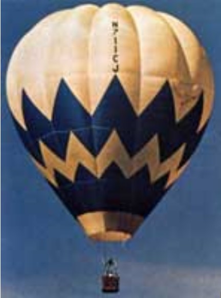
Thunder’s first U.S. sale was Cactus Jack, sold to Bob and Marge Ruppenthal, the Albuquerque couple at whose house the Thunder contingency stayed while campaigning Jumpin’ Jack in the ’73 Worlds. After modifications, the balloon was re-registered as a “Ruppenthal Eagle.”