Persons: 1
Diameter: 40 ft
Height: 60 ft
Volume: 30 cu.ft
Weight: 258 lb
Payload: 481 lb
Burner: 8 Million BTU/hr
Fuel capacity: 19 USG
Cost: (1972): US$ 4600
FAI AX-6
Post WW2
Semco Balloons
Route 3, Box 514
Aerodrome Way
Griffin
Georga 30223
USA
Balloon builder
Selcher JS-1
In 1978 John Selcher built the Selcher JS-1, two place, open cockpit biplane, registered N67JS.
Engine: Lycoming O-235, 108hp
Wing span: 26’0″
Length: 17’0″
Useful load: 573 lb
Seats: 2
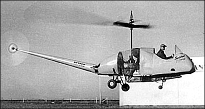
Seibel S-4 / YH-24 Sky Hawk
Charles Seibel began development on the S-4 after forming the Seibel Helicopter Company with funding from local Kansas oil investors. The S-4 was a continuation of his work on his previous design, the Seibel S-3, which he flew as a demonstrator for his design concepts; primarily a new design for a two-bladed rotor system and a simplified transmission. These features would also be incorporated into the S-4 design.
The S-4 frame was a welded steel-tube box frame, with two decks. A lower deck supported the control panel, pilot’s seat, wheeled, tricycle landing gear, and a small passenger/cargo area accessible from the rear, and an upper deck carried the engine, the fuel and oil tanks, and supported the transmission and rotor assembly. A tapered, monocoque, alloy tail boom with a two-bladed antitorque tail rotor was attached at the rear of the upper deck.
In January 1949, the S-4 N5152 c/n 1 lifted off the ground for the first time, piloted by Johnny Gibbs. In March 1950, certification tests were completed and on 23 April 1950, the S-4 received civil certification by the CAA.

Both the U.S. Army and U.S. Air Force showed interest in the S-4. In early 1951, the U.S. Army ordered two examples for operational and engineering evaluation in the observation, utility, and aeromedical evacuation roles. The Army designated the S-4 as the YH-24 Sky Hawk. The first Sky Hawk, serial number 51-5112, was delivered to Fort Bragg, North Carolina in April 1951 and returned to Cessna in 1952; the second YH-24, serial number 51-5113, was delivered to Wright Field, modified to S-4B. YH-24 51-5113 with a 165hp Franklin 6A4-165-B3, was modified as a side-by-side trainer for Army testing at Fort Sill OK. Both ships were eventually scrapped by Cessna.
Despite the simplicity of the S-4, the Army determined that it did not provide a sufficient payload capability and the aircraft were dropped from the inventory and returned to Seibel in 1952. Only the two were built.
A larger engine, the Lycoming O-290B with 125 hp, would be installed in the aircraft and side-by-side seats, making it the 1950 S-4A N5153 c/n 2. Flight tests by CAA’s Hal Hermes.

Based on feedback from the Army during the evaluation, Seibel, shortened the fuselage of the second YH-24 (51-5113) and widened the cockpit for a co-pilot’s seat next to the pilot’s seat. Seibel also replaced that aircraft’s original wheeled, tricycle undercarriage with landing skids. This aircraft would become the S-4B. The S-4B would serve as the basis for the design of the Cessna CH-1 Skyhook, the only helicopter Cessna ever produced.
Variants:
S-4
Original design, certified by the CAA in 1950.
S-4A
Featured an upgraded, 125 hp Lycoming O-290B engine.
S-4B
Modified airframe based on Army recommendations during YH-24 evaluation. Two-seat cockpit and skid landing gear.
Specifications:
S-4 Skyhawk
Engine: 108hp Lycoming O-235-C1
Rotor: 29″2″
Length: 27’10”
Useful load: 580 lb
Max speed: 65 mph
Cruise: 58 mph
Range: 100 mi
Ceiling: 4300′.
Seats: 2 tandem
S-4A
Engine: 125hp Lycoming O-290-B
Length: 24’6″
Seats: 2-3
YH-24
Engine: 1 × Lycoming O-290-D, 125 hp (93 kw)
Rotor diameter: 29 ft 11⁄2 in (8.88 m)
Disc area: 666 sq ft (61.9 m2)
Length: 27 ft 10 in (8.48 m)
Height: 10 ft (3.05 m)
Empty weight: 960 lb (436 kg)
Max. takeoff weight: 1,540 lb (700 kg)
Maximum speed: 65 mph (105 km/h)
Cruise speed: 58 mph (93 km/h)
Range: 98 mi (85 nmi, 158 km)
Service ceiling: 4,300 ft (1,310 m)
Rate of climb: 700 ft/min (3.6 m/s)
Crew: 1-2
S-4B / YH-24
Engine: 165hp Franklin 6A4-165-B3
Seats: side-by-side
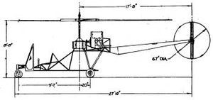
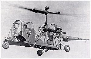
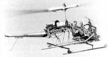
Seibel S-3

With two collaborators Seibel built in 1947 the S-3 light helicopter with lateral and longitudinal control effected by changing the center of gravity. Each blade attaches to the rotor hub with the help of a piece of bent sheet metal. This formed an angle that could be “twisted” to control changes in pitch. The advantage of this design is how mechanically simple it is. There is no need for bearings, hinges or dampers.
A moveable cabin section shifted in response to “cyclic” stick inputs, thereby shifting the c/g and causing the machine to act accordingly. This was soon abandoned (insufficient control and the potential for roll-over on a hard landing) and replaced by a more conventional cyclic control system for testing and promotional flying.
S-3 NX735B c/n 1 was built in a cellar from miscellaneous spare parts, including a truck differential and an automotive clutch.
The S-3, NX735B, first took flight on 4 September 1947 and flew mainly to demonstrate Charles Seibel’s simplified two-bladed rotor system and transmission.
Most design and features evolved into the Cessna CH Skyhook.
Engine 65hp Franklin
Rotor diameter: 7.62m
Loaded weight: 365kg
Empty weight: 245kg
Cruising speed: 112km/h
Inclined climb: 275m/min
Absolute ceiling: 3660m
Seats: 1
Seibel Helicopter Co
1943: (Charles W) Seibel,
Kenmore NY
USA
(while working for Bell Co).
1946:
Wichita KS
USA
(while working for Boeing Co on XL-15).
In 1943 designed the Seibel S-1 twin-tilt rotor. Preliminary first design, patented in March 1944.
With two collaborators built in 1947 S-3 light helicopter (lateral and longitudinal control effected by changing center of gravity).
The S-2 of 1947 was a single-place open coaxial design study. No specs or data found.
Established early 1948 Seibel Helicopter Co Inc, Wilson Field, Wichita.
S-4A of 1948 had special blade-attachment system patented for S-3. Followed by S-4B with more powerful engine and side-by-side seats.
1949: 5613 N Broadway,
Wichita
USA
1951; 3400 N Broadway,
Wichita.
USA
In March 1952 company taken over by Cessna.
Seguin
Company established 1967 to produce a conversion of the Piper twin-engined Apache. Known as the Seguin/Piper Geronimo, it had more powerful engines, and many refinements to the original structure and equipment.
Seedwings Sensor / Seedwings Europe Sensor
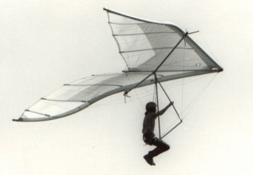
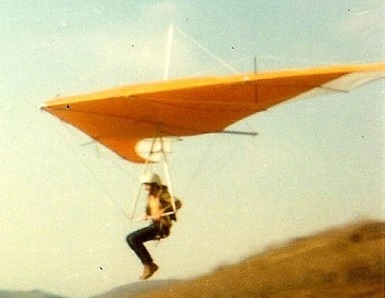
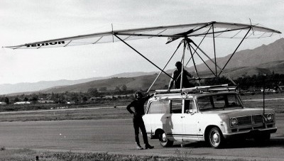
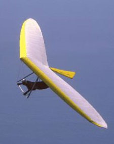
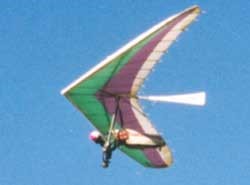
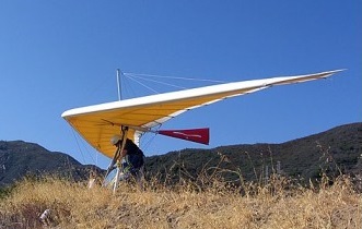
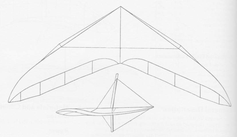
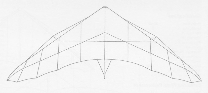
The Sensor 1 was a 1975 hang glider which featured a double surface sail and swept truncated tips. It was very stable in comparison to most high performance gliders, faster than most standards, and with good penetration. It has positive dive recovery with full sail deflation because of rigid truncated washout. This glider has been the test bed for diffusor tip theory in flex membrane wings.
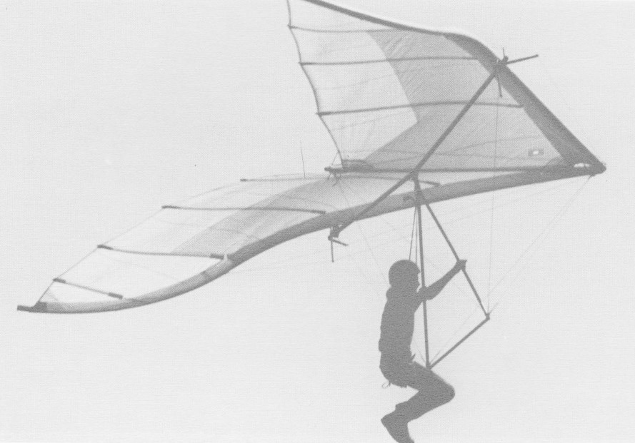
The Sensor I airframe is made from 6061-T6 1.75in x .049 anodised aluminium tubing and all rigging cable is 3/32in 7 x 7 vinyl coated stainless steel aircraft quality. All hardware is aircraft quality, and the sail is made from 4.25oz and 3.0oz stabilised dacron, then available in white only.
There was the option of seated or prone harness.
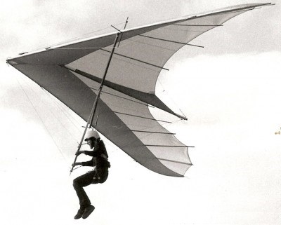
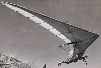
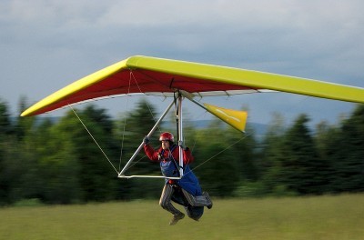
The Sensor 2 was from 1976 featured Flare Tips advanced tip design. This eliminates tip stall during steep banked turns and parachuting. The wingtips are extended with a Flare Tip Batten which allows the tip to flex in the angle of attack. The airfoil is a semi-double surface inflated type.
The Sensor II’s Flare Tips gives it a tip inertia that is lower than most. This is very light and flexible concept allows for rapid turn response, light tip gust effects, lower induced drag and improved washout distribution. The airfoil gives high L/D and low moment. The keel is reflexed and cambered for positive pitch moment.
The airframe is made from 6061-T6 and 2024-T3 aluminium tubing that is doweled and bushed. All rigging cable is 3/32in 7 x 7 vinyl coated stainless steel aircraft quality. All hardware is aircraft quality.
The sail is made from 3.8oz Howe & Bainbridge stabilised dacron with reinforcement in stress areas and double zig-zag stitched. The sail is fully battened. Seated or prone harness support sysems were options.
The Sensor 210B is from 1976.
The Sensor 210C is from 1977.
The Sensor 210E is from 1979.
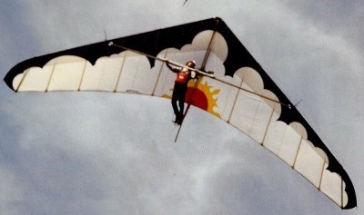
Construction plans were available for the Sensor 210E, all in inches and AN standards, and available in two sizes. The Sensor at that time was “the ultimate flying machine”. Bob Trampenau has been the inventor of curved flexible wingtips. Despite the fixed crossbars (floating crossbars) and big span it was easy to roll. Now, it handles like an ocean vessel.
Both the Sensor 310A and Sensor 310B were 1977 models.
The Sensor 411A was also a 1977 hang glider, followed by the Sensor 411B in 1978.
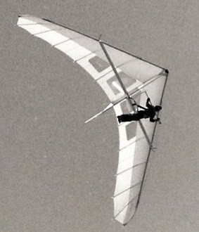
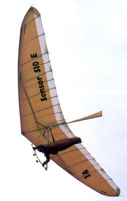
The 1985 Sensor 510 was for advanced pilots.
The Sensor 610 came in 1992.
Seedwing Europe was authorized to produce the model “Sensor 610-144” until 1993. At the end of the contract, they continued to produce the “Sensor” under the name of “Seedwings Europe” without the agreement of Bob Trampenau.
The Sensor 610 CF3 was a 2000 version for advanced pilots.
The 2005 Sensor 610 CF4 was for advanced pilots.
The 2007 Sensor 610 CF5 was for advanced pilots.
The 2008 Sensor 610 F5 was for advanced pilots.
Seedwings produced the Sensor 610 and, in 1993, the Sensor 611.
The 1986 Sensor 710 was for advanced pilots.
Sensor I
Keel length: 7.5 ft
Wing span: 29.5 ft
Wing area: 145 sq,ft
Aspect ratio: 6
Nose angle: 110˚
Sail billow: .025˚
Weight: 45 lb
Pilot weight: 130-160 lb
Takeoff speed: 15 mph
Stall speed: 16 mph
Max speed: 45 mph
Best glide ratio (L/D): 8-1
Best L/D speed: 25 mph
Min sink: 275 fpm
Sensor II
Keel length: 9.2 ft
Wing span: 32.8 ft
Wing area: 165 sq,ft
Aspect ratio: 6.5
Nose angle: 110˚
Sail billow: 0.5˚
Weight: 36 lb
Pilot weight: 140-180 lb
Takeoff speed: 12 mph
Stall speed: 14 mph
Max speed: 45 mph
Best glide ratio (L/D): 9-1
Best L/D speed: 25 mph
Min sink: 225 fpm
Sensor 210E 183
Wing area: 17m²
Wingspan: 10,5m
Sensor 510
Wing area: 14.96 m²
Wing span: 10.6 m
Aspect ratio: 7.5
Hang glider weight: 30 kg
Number of battens: 20
Sensor 610
Wing area: 13.5 m²
Wing span: 10.4 m
Aspect ratio: 8
Minimum pilot weight: 60 kg
Maximum pilot weight: 85 kg
Nose angle: 127°
Sensor 610 CF3 135
Wing area: 12.63 m²
Wing span: 10 m
Aspect ratio: 8
Hang glider weight: 30 kg
Minimum speed: 32 km/h
Maximum speed: 104 km/h
Max glide ratio (L/H): 15
Minimum sink rate: 0.76 m/s
Packed length: 5.2 m
Sensor 610 CF3 142
Wing area: 13.19 m²
Wing span: 10.4 m
Aspect ratio: 8.1
Hang glider weight: 32 kg
Minimum speed: 32 km/h
Maximum speed: 104 km/h
Max glide ratio (L/H): 15
Minimum sink rate: 0.76 m/s
Packed length: 5.3 m
Sensor 610 CF3 150
Wing area: 13.93 m²
Wing span: 10.7 m
Aspect ratio: 8.2
Hang glider weight: 33 kg
Minimum speed: 32 km/h
Maximum speed: 104 km/h
Max glide ratio (L/H): 15
Minimum sink rate: 0.76 m/s
Packed length: 5.5 m
Sensor 611
Wing area: 14.4 m²
Wing span: 10.85 m
Aspect ratio: 8.2
Minimum pilot weight: 75 kg
Maximum pilot weight: 105 kg
Nose angle: 127°
Sensor 710 145
Wing area: 10.12 m²
Wing span: 13.47 m
Aspect ratio: 7.6
Hang glider weight: 29 kg
Minimum pilot weight: 70 kg
Maximum pilot weight: 85 kg
Packed length: 5 m
Number of battens: 14
Nose angle: 132°
Sensor 710 152
Wing area: 10.43 m²
Wing span: 14.12 m
Aspect ratio: 7.7
Hang glider weight: 30 kg
Minimum pilot weight: 77 kg
Maximum pilot weight: 102 kg
Packed length: 5.2 m
Number of battens: 14
Nose angle: 132°
Seedwings Sunseed

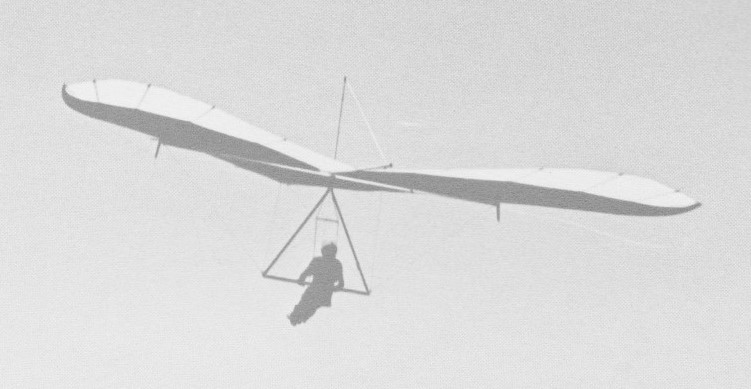
The 1975 Sunseed is a double surface, diffuser tip flying wing. It has outboard control surfaces. Canted tip wings provide self righting characteristic. It has a fibreglass leading edge with an aluminium trailing edge wedge. Draggons on the wing tips can be operated as glide path control devices to reduce glide angle from 12-1 to 5-1. The wing tip design provides induced drag and tip vortex reduction. The lower wing surface is ribless.

The airframe is made from 2024-T3 anodised aluminium. Rigging cable is 3/32in 7 x 7 stainless steel aircraft qualiy, vinyl coated. Hardware is all aircraft quality parts. The sail is 1.8oz stabilised dacron and is fitted with zippers and Velcro tapes. There was the option of seated or prone harnesses.
The Sunseed dissembles to a bundle 10 ft long and 1 ft in diameter.
The Sunseed has a stable stance even in steep turns with no tendency to dive or stall.
The run out distance before touchdown is about four times that of a Rogallo. It has a 13.7% airfoil and a load factor of 6G.
Wing span: 32.8 ft
Wing area: 128.5 sq,ft
Aspect ratio: 8.36
Wing sweep: 15˚
Weight: 50 lb
Pilot weight: 125-180 lb
Takeoff speed: 15 mph
Stall speed: 16 mph
Max speed: 40 mph
Best glide ratio (L/D): 12-1
Best L/D speed: 25 mph
Min sink: 275 fpm
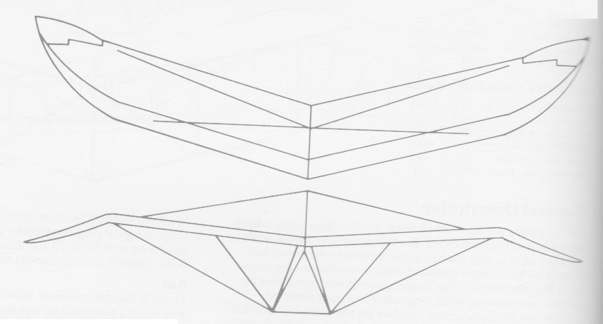
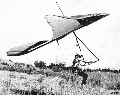
Sedpa Gerfaut
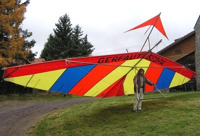
A 1976 hang glider for advanced pilots. The duck design was supposed to prevent luffing dives, but according to Vol Libre, the wing was not flyable at speed.
Hang glider weight: 25 kg
Packed length short: 5.30 m
