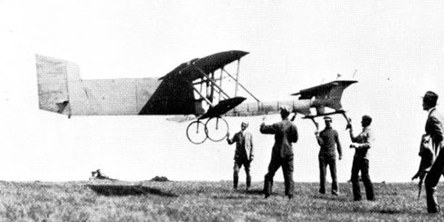
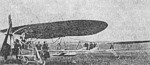
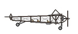
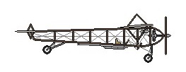
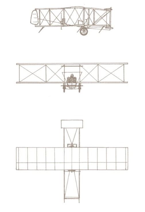
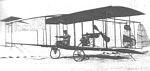
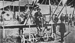
The 1910 Bueno et Demaurex pusher biplane, designed by Bueno and Demaurex in France. built by Avia. Featured two propellers on outriggers.
Span: 49’2″
The 1910 Bueno et Demaurex pusher biplane, designed by Bueno and Demaurex in France. built by Avia. Featured two propellers on outriggers.
Span: 49’2″
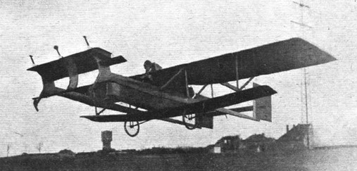
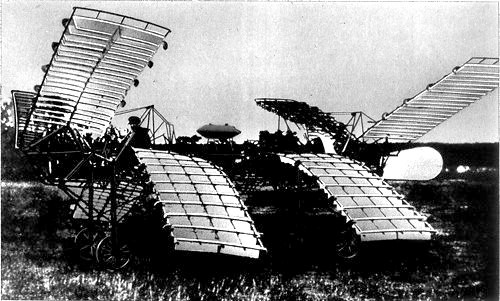
Among the machines entered in the Rhön competition in Germany in 1921 was a canard-type glider, designed and built by Friedrich W. Budig. It is a sesquiplan: in fact, the lower wing is of smaller span and chord than the main wing. The canard stabilizer in the front, in two parts: the main part serving for automatic longitudinal stabilization, and behind the latter, a conventional flap for controlling the attitude, actuated by the pilot. On both versions, there is also a horizontal plane at the rear, of very small surface, which seems to be fixed.
The machine featured an original automatic device for controlling the pitch stability.
At the beginning of 1923, Flight International published an article which re-spoke of the machine of F. Budig, in a new version, with a fuselage deeply modified in its rear part, in order to install a motor there. It was a BMW flat-twin motorcycle engine developing 4 hp. The propeller being mounted in direct engagement with the motor.
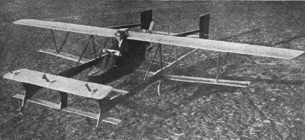
It seems that the power developed by the engine was not sufficient to allow a take-off of the machine without assistance of a catapult. Once in the air the machine had to be able to fly horizontally, or at best to climb with a low rate of climb. The motorization was only allowed to prolong the flight somewhat.
In May 1924 there was the second Rossiten-free flying contest near Koenigsberg (West Prussia). This contest was a landmark in the history of gliding, as it saw the world record of duration extended to 8 hours 42 minutes 9 seconds by Ferdinand Schultz with his FS-3 Besenstiel (May 11, 1924). Hentzen and Budig participated in the contest and both announced that they intended to purchase a Blackburne engine to equip their respective gliders.

Budig replaced the initial BMW with a Salmson A.D. 3. This engine, manufactured by the Salmson Motors Company, Billancourt, France, of a little less than 1000 cc displacement, developed 12 CV (18 kW) at 1800 rpm and weighs 34 kilograms.
This engine proved its worth in the 1920s by winning the Grand Prix de la Moto-Aviette and the Prix Solex (in 1925).
F.W. BUDIG
Flying machine
Application filed June 16, 1921
1,419,447 Patented June 13, 1922
To all who it may concern:
Be it known that I, FRIEDRICH WILHELM BUDIG, citizen of the state of Prussia, residing at Falkenberg-Grunau, near Berlin, in the state of Prussia, Germany, have invented certain new and useful Improvements in Flying Machines (for which I have filed applications in France, Aug. 1, 1914, and in Germany Jan. 29, 1920 and Nov. 20, 1920), of which the following is a specification.
This invention relates to a steadying device. It consists in the combination of the supporting planes with an adjustable steadying plane. This later plane is rotatably supported on an axle supported in its turn by the flying machine, and its forms, together with an immovable surface with which it is connected, preferably by bellows,
a hollow space within a depression may be produced in known manner by the mediation of a surface feeler. The steadying plane is adjusted to various inclinations by which depression, contrary to the action of a spring. Besides these arrangements, the present invention also relates to means for correctly adjusting the steadying plane, as is particularly necessary for soaring flying apparatus.
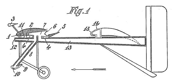
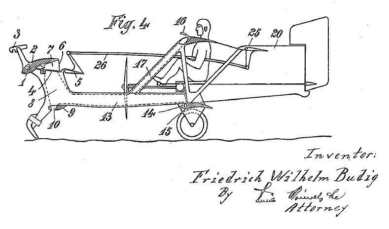
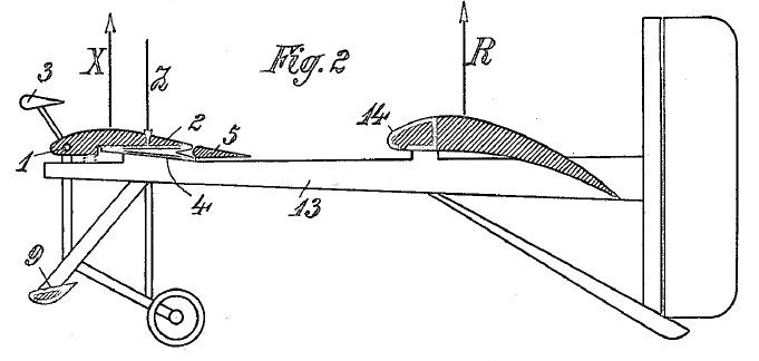
Reffering to the accompanying drawing, Figure 1 is a vertical section through a motorized flying machine with a novel device in question being shown in the position it occupies at too slow flight; Figure 2 is a side-view of the machine, only some upper parts (2, 5, 14) in section, and the position of the automatic steadying being that it occupies at normal speed; Figure 3 is a diagrammatic illustration of the succession of the swing motions of the machine; and Figure 4 is a side view of a soaring flying machine having a small auxiliary motor.
The upper body 2 of the steadying plane is hinged to a horizontal axle 1 firmly supported by the frame of the flying machine. Affixed to said body 2 is a counterpoise 3, the arrangement being that the total center of gravity of the poise and the body 2 is located above the common axis of rotation the law of inertia initiates a favorable swinging or turn of the upper body 2.
Parallel with the body 2, and having the same breath as this body, is an immovable flat 4, to the rear of which is hinged the horizontal rudder 5 for altitude steering.
The body 2 and the plate 4 are connected with each other by bellows 6 forming or enclosing a chamber 7 which communicates by a channel or passage 8 with the hollow feeler plane 9 which has the shape of an inverted supporting and is provided with a slot 10 extending over the whole of its breadth. 11 is a spring which tends to turn the body upwards about the axle 1, that is to say, to expand the bellows. The position of the parts 2 and 6, if no partial vacuum within the bellows counteracts the spring, is that shown in Figure 1.
The bellows communicates with the atmosphere not only through the channel 8, but also through an aperture 12 which is at the front of the machine and constantly open.
The sectional area of the aperture 12 is smaller than that of the slot 10. The supply of the air through the aperture 12 does not materially affect the degree of rarefaction in the bellows as long as the air entering through that aperture flows off through said slot, as in the case during flying with normal speed. But if the speed decreases, the body 2 can rise, under the pressure of the spring 11, far more quickly than would be the case if no supply of air through the aperture 12 would take place, because, as is known by experience, air, even at reduced speed, can enter only with great difficulty through the slot 10 into the bellows.
In order to accelerate the swinging movement of the body 2 in the direction to the plate 4 at an increase of the speed of flight, the space 7 is connected by one or more air-channels 13 provided in rigid parts of the structure preferably tubes, and forming a kind of girder with the spaces of hollow bodies 14 united with the main supporting planes.
The tubes 13, or their equivalents, carry the above described combination and arrangement of parts and serve also for fastening the means provides for the landing.
The hollow body 14 forms a rigid piece for and of the supporting plane and its front portion the blowing-at edge of said plane. The supporting wall of that body 14 differs from an ordinary hollow supporting plane chiefly by a slot 15 which is provided in the lower surface of the projecting front part of the body 14, similarly to the slot 10, and the length of which is about one fourth of the length of the slot 10, provided, that the machine has an aperture such as 12.
By measurements it is known that at that place of the supporting frame profile where the slot 15 is located a strong depression is produced at quick flight.
This observation confirms that at slow flight the slot 15 assists the action of the aperture 12, and at quick flight assists the action of the slot 10.
Thus, if the angle of incidence at which the flight takes place is reduced, then, by the addition of the slot length 15 with the slot length10, a certain definite amount of air to be sucked out of the bellows space 7 is exhausted more quickly and the body 2 moves correspondingly quicker in the direction of the plate4 ; that could not be the case without the slot 15.The manner in which the body 2 is turned in the one or the other direction will become clear from a description dealing with flying in soaring manner, as follows :
Supposing the machine be soaring motionless in a constant head-wind under a large angle of incidence. In this case the lifting power R acts at the main supporting plane, and the lifting power X acts at the steadying surface. The lifting power of the horizontal rudder 5 which latter is controlled by the hand of the pilot, and the buoyancy
of the stationary plate 4 may be neglected in these considerations because said two influences approximately compensate the downwardly directed power of the receptacle 9.
Besides the lifting power X, also the power of the spring 11 acts upon the body 2, in the same direction as said power X, and, furthermore, also the suction power Z which is produced in the space 7 by the depression and acts in the opposite direction. These three powers balance each other at normal flight and determine the profile of the steadying surface, as illustrated in Figure 2.
Now, if the wind relatively to the flying machine, suddenly grows stronger owing to a squall or gust, then also the powers X and R increase at the same time.
Although also the suction power at the slot 10 becomes greater at the same time, still, the power Z does not immediately vary because the amount of air to be led away is increased by the supply of air taking place through the aperture 12 and 15.
Besides, the increased suction power at the slot 12 which tends to increase the power Z is opposed by three other powers. Firstly, the increased lifting power X tends to turn the body 2 upwards which is made possible only by air entering through the apertures 12 and 15. Secondly, the flying machine is, at the commencement of the squall
or gust, at first shoved backward by reason of the additional resistance, in consequence of which the high-lying center of gravity of the body 2 and the poise 3 swing forward by reason of their inertia ; thirdly, this latter cause makes the air present within the channel 13 move in the direction to the space 7.
A sudden increase of the lifting power X by an outer wind power causes, thus, the body 2 to swing upwards, whereby the additional buoyancy at the front of the machine is made ineffective.

Matters are different with the rigid main supporting surface at which the power R has been increased. The diagram of forces (Figure 3) shows that the front of the machine has remained at the point C, owing to the annihilation of the addition to the power X, whereas the main supporting plane ascends from A to B.
The swinging motion in forward direction occurring at the rear part of the machine being lifted entails forward drive, whereby the speed of the machine is increased and, also a variation in the play of forces at the steadying devicer is brought about.
As the angle of incidence at the main supporting plane has become smaller by reason of the additional upward motion, suction takes place at the slot 15, and as also the opposing forces that acted upon the body 2 do no more exist, this latter is turned in the direction of the plate 4 whereby the buoyancy at the front of the machine is increased and this latter rises from the position C to the position D.
From both successively occurring motions of the flying machine results that this latter is rising for the height H without a loss of speed.In the practical application of the arrangement in question a greater measure than the length C-A which is chosen only by way of example will be given the radius of oscillation; that may be easily attained by only partially annihilating, by the means stated, the power increased by the squall or gust.
Owing to its dimension, the rear rim of the movable body 2 forms for the pilot a readily visible indicator of the conditions of motions of the flying machine.
The pilot may at his discretion either promote the indications of the rear rim or edge of the body 2 by appropriately operating the horizontal rudder or oppose them, also by appropriately actuating said rudder, for instance at landing.
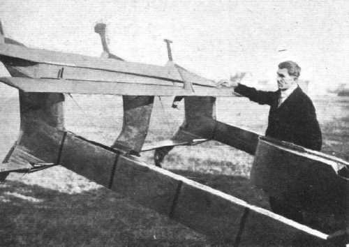
The flying machines with but slight load per unit of surface are easily overturned by wind after the landing. The soaring flying machines shown in Figure 4 is so constructedthat the wind cannot lift its front part off the ground because an aperture is provided which is kept closed during the flight by a flap 16, but permits of a large supply of air through the channel 17 if it is open, so that the steadying plane is ensured against being drawn against the plate 4.
In testimony whereof I have affixed my signature in the presence of two witnesses.
FRIEDRICH WHILHELM BUDIG
Witnesses: FRANGE SURNAM and EMIL VORWERK.
Brothers Wincent and Rudolf Schindler, wealthy millers from Kraków, built in 1908 a working model airplane and in 1910 they commissioned a talented engineer Henryk Brzeski to build a plane to their ideas, named Aquila (Latin for “eagle”). In August 1910 it was demonstrated on the ground to emperor Franz-Josef I, and several days later a test-flight attempt was made, during which it crashed into a fence at the outskirst of the airfield.
Span: 32’10”
Length: 32’10”
Weight empty: 660 lb
pilot and 2 passengers
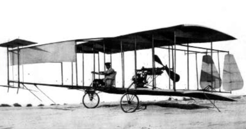
This machine was built for the inventor, Erhard Brunsmann of Berlin-Eichwalde, Germany, by Edmund Rumpler in Berlin-Johannisthal. The tandem wings were driven by a complex patented crank mechanism and it was intended that control would be achieved by differential flapping of the wings, rather than by separate control surfaces. Lange dismisses it in little more than two lines as a “Fehlkonstruktion”.
Built by the “Fabbrica Italiana di Aeroplani” of Turin, Italy, in 1910. Claimed to be well designed but too heavy.
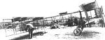
The 1910 Brunet Tandem biplane was designed and built by Brunet in France.
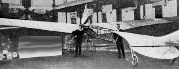
Juan Olivert, in company with his friend and engineer Gaspar Brunet, undertook the building a biplane inspired by that of the Wrights, but also influenced by the French Farman and Voisin. Built in Barcelona in the workshops of Rosell y Vilalta, with dried ash and beech wood, Brunet’s airplane had a double helm front and a rear stabilizer tail, on which a double rudder was supported, since the plane lacked ailerons. The flight controls consisted of a lever topped by a bicycle handlebar for attitude control and pedals for steering. The throttle control was operated by cables attached to a lever. The engine that propelled it had to be a 25 HP Anzani.
On Sunday September 5, 1909 and with the assistance of the Mayor of Valencia, Mr. Maestre, as well as the designer of the plane, Mr. Brunet, Juan Olivert climbed onto the wicker chair, then started and proceeded to an engine test, which was followed by a check of the suitability on the ground. Then, the makeshift pilot put on power and the plane flew, rising tens of centimeters off the ground, according to the press the next day, and traveling between 30 and 50 meters, until when Olivert tried to modify the course of his flight to avoid carob trees, the plane suggested a loss of speed, immediately returning to earth, where an existing trench in the ground damaged one of the wheels, later spreading to various parts of the plane. This being the first flight made in Spain. As for the plane, there are indications that it was repaired and even went on to do some other flight.
There’s at least one replica of the machine, at the Madrid “Museo del Aire”.
Engine: Anzani 25 HP
Wingspan: 10.50 m
Length: 7.50 m
Weight: 350 Kg
Total weight: 430 Kg
First flight: September 5, 1909

The “Brumah I” was the first machine built by the two seventeen-year-old Harry A. Bruno and Bernard H. Mahon (hence the name) of Montclair, New Jersey, crashed on its first flight from the barn. The Brumah II, with a span of only 16 feet, was called the world’s smallest monoplane. It was flown on sled runners down an ice-coated hill on Christmas Eve 1910. It crashed then too but might have been re-built, but there is no indication that it was ever actually fitted with a motor.
The Brunet-Olivert 1909 biplane was designed and built by G. Brunet y Viadera and J. Olivert in Spain.
The 1911 Brumarescu “Columba” (dove) 2-seater biplane was designed and built by Dumitru Brumerescu in Romania.
