Horgan 1903 Flying Machine

This unusual ornithopter was designed by William C. Horgan together with partners Theophilus Williams and M. Halsinger. It had six wings attached along each side of its five-foot diameter tubular fuselage, intended to make 90 beats per minute driven by a 3.5 hp vapour engine. The framework was made of aluminium and was claimed to weigh only 200 lbs, with the passengers intended to sit in a cage below the fuselage. The machine crashed during a test, putting an end to the Canadian-born Chicago inventor’s dreams of profitable passenger-carrying flights and his plans to participate in the 1904 St Louis Aeronautic Competition.

Hohl H1 / H2 / H3 / H4 / H5 / Eindecker

Hohl 1910 Eindecker H 3

Electrician Hans Hohl was not a successful aviator and little is recorded of his designs. None of his machines is known to have flown; the main criticism of Hohl always given to his non-existent airfoil. Even in 1912, when the army allowed the use the Exerzierplatz at Halle-Beesen – 10 or so miles from Merseburg, south of Berlin – the last-known of his monoplanes, “Hohl-5”, failed to make a sustained test flight.

Holbrook 1910 Aeroplane

High-wing monoplane designed by Arthur Erritt Holbrook and built by the Holbrook Helicopter Aeroplane Co. in Joplin, Missouri. At around the time of the founding of his company, Holbrook also filed (January 19, 1910) to patent an Aeroplane; rather a tandem wing monoplane fitted with both tractor propeller and vertical rotors – hence the name of the firm. Four years later, on February 10, 1914, Holbrook was finally granted US Patent 1,086,916 for his invention. It is reasonable to assume that this photographed machine, with shafts protruding above the wing, was a “first draft” to be augmented to a form visible in the patent of Holbrook, where two rotary propellers are visible. After its appearance in 1910, Holbrook’s aeroplane was never heard from again.

H.M. Balloon Factory No.9 / Vickers R.9

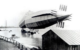
Plans to build a second rigid airship to follow the unsuccessful HMA No. 1 (His Majesty’s Airship No. 1) Mayfly were agreed by the Committee for Imperial Defence in early 1913, and that Vickers should be asked to design an improved class of ship incorporating all that was then known about the Zeppelins. Vickers’ airship design department had been disbanded following the failure of the Mayfly, consequently a new department was formed when the original design team was reassembled with H. B. Pratt recruited as chief designer. Pratt had been working at Vickers while the Mayfly was being constructed and had predicted that it was not structurally sound and subsequently left the company. Pratt in turn hired Barnes Wallis, whom he had met while both were working for the shipbuilding firm of J. Samuel White, as his assistant. The initial order for the new ship was placed on 10 June 1913, with the final plans being agreed at the end of the year, and a formal contract was signed in March 1914.

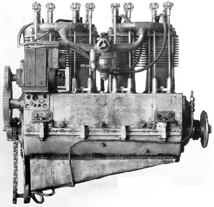
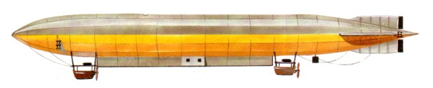
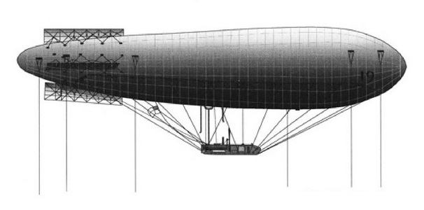
The initial specification called for an airship with a disposable lift of 5 tons (5080 kg) capable of flying at 45 mph (72 km/h) and maintaining an altitude of 2,000 ft (610 m) for 30 minutes; however, the required load was later reduced to 3.1 tons (3150 kg). The hull was cylindrical for most of its length and was constructed from 17-sided transverse frames with a triangular section keel underneath. Two gondolas were suspended from the keel, the forward one containing the control compartment and two of the engines, the aft containing an emergency control station and the remaining pair of engines. In addition there was a radio cabin and a mess space for the crew within the keel structure, which also contained the fuel and ballast tanks. Propulsion was provided by four 180 hp (130 kW) Wolseley engines, mounted in pairs in the gondolas. Like Mayfly, it was designed with watertight cars so that it could be operated from water. The design was based in part on French plans of Z IV which had landed in France on 3 April 1913 following an accidental incursion into French airspace, permitting a thorough examination.

Construction was delayed by a number of circumstances. Difficulties were encountered with the fabrication of the duralumin girders for the transverse frames, and there were many changes to the design, including strengthening the hull so that it could be handled safely by inexperienced crews, and replacing the original drive arrangement of paired propellers mounted on the sides of the hull with swivelling propellers mounted on the gondolas (as used on contemporary British Army dirigibles).

The construction shed at the Cavendish Dock at Barrow was too small for the new design so a new hangar was built at Walney Island, off the west of Barrow. The new shed was 540 ft (160 m) long, 150 ft (46 m) wide and 98 ft (30 m) high, and had a 6 in (15 cm)-thick concrete floor with handling rails embedded into it which extended 450 ft (140 m) into the adjacent field. As a safety measure the shed had eight fire extinguishing jets fed by a dedicated reservoir. A gasbag factory employing 100 staff was also set up beside the shed.

When World War I broke out on 4 August 1914 No.9r was nearly ready for erection, and despite competing demands for materials and manpower for other projects, construction continued during the first months of the war. However, there was a feeling that the project was no longer favoured by the Admiralty: Winston Churchill, then First Lord of the Admiralty was known to be unenthusiastic about airships, and on 12 March 1915 he cancelled the order for the ship. The reasons given for this decision were that it was expected that the war would be finished in 1915, and that the vessel would not be operational by then and thus was a waste of valuable resources.

On 19 June 1915, after Churchill had been replaced as First Lord by Arthur Balfour, a conference was held at the Admiralty to consider all airship development. At that time the non-rigid airship programme was proving to be successful, and at this meeting it was agreed to expand the non-rigid programme and also to resume construction of HMA No.9. However, resumption of work was delayed by the necessity to retrieve Pratt and Wallis who had enlisted in the Army when construction was cancelled. Final erection of the ship began in the autumn of that year, but there were delays in obtaining flax from Ireland to make nets for the gasbags following the Easter Rising, and the ship was not completed until 28 June 1916.

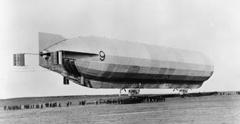
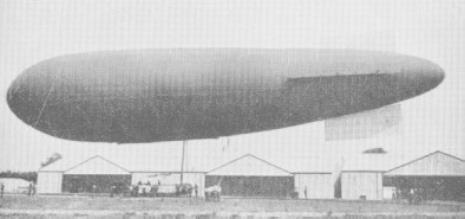
On 16 November 1916, No. 9r left its shed and was moored outside for tests of the fittings and engines, the first test flight taking place on 27 November 1916. This was the first time a British rigid airship had flown; however, it was unable to lift the contract weight of 3.1 tons. It was therefore lightened by the removal of both rear engines, replacing them with a single engine that had been salvaged from the Zeppelin L 33 which had made a forced landing in Little Wigborough, Essex, on 24 September 1916. New, lighter, gasbags were also fitted. These modifications increased the disposable lift to 3.8 tons (3861 kg), and it was accepted by the Navy in April 1917.

It served a useful purpose, however, it had become the basic pat¬tern on which the four rigid airships for the Admiralty were later to be based. The first of these ‘23’ class airships, HMA No. 23, was subsequently deli¬vered from Vickers Limited, Barrow¬-in-Furness, to Pulham on 15 Septem¬ber 1917.

No.9r was then sent to the RNAS airship station at Howden in the East Riding of Yorkshire where it spent most of the time being used for experimental mooring and handling tests. From 17 October 1917 to June 1918 it was stationed at RNAS Pulham in Norfolk where it was finally dismantled due to demand for shed space to allow construction of newer airships, having spent 198 hours and 16 minutes in the air, of which some 33 hours were at a mooring mast. Although unable to compete against contemporary Zeppelins, No.9r provided valuable experience of handling a rigid airship and the use of mooring masts, which would evolve into a unique method of mooring airships.

Engines: 4 × Wolseley, 180 hp (130 kW) each
Volume: 846,000 cu ft (24,000 m3)
Length: 526 ft 0 in (160.32 m)
Width: 53 ft 0 in (16.15 m)
Useful lift: 8,500 lb (3,900 kg)
Maximum speed: 43 mph (69 km/h, 37 kn)

H.M. Balloon Factory No.1 (RI) / Mayfly

The UK’s first rigid airship was proposed in 1908 as a means of evaluating the naval airship as a weapon of war along German lines, and an order was placed with Vickers. The work was to be undertaken by a joint civilian/naval team, few of whose members had much experience in the type of work involved. Since the vessel was to be flown from water her gondolas were given planing bottoms, although alternative mooring to a mast anticipated German ideas. Construction was to be of the new alloy duralumin as a compromise between those factions who wanted wood or steel. Engine tests were begun in mid-February 1911, and it was hoped that the maiden flight might coincide with the Coronation Review of the fleet by King George V.

The extraction of HMA No. 1 (RI) from its floating shed called on the resources of a number of tugs and a hauling party of 300 sailors on the ropes, a difficult task since the airship, now nicknamed Mayfly (its official designation was ‘HMA Hermione’), proved much heavier than expected. This combined with misdirection of the handling party or (according to some reports) a sudden cross-wind, caused the airship to strike one of the uprights of the shed entrance, some damage resulting. This was unfortunate, since an earlier sojourn in the open had seen the airship successfully moored to the short mast provided as the superstructure of a naval vessel (the first use of such equipment in history) and reports speak of the RI thus riding out a storm with winds rising to as high as 72 km/h (45 mph).

The damage now sustained had to be repaired, and the airship’s return to its shed also provided an opportunity to lighten the structure. It was not until 24 September 1911 that the RI next appeared, fully loaded with hydrogen after a 10-hour inflation of the gas cells and ready for flight. The method of handling was as before, and it was necessary for the airship’s nose to be turned. Hardly had the strain been taken on the ropes than a loud crashing was heard from within the centre of the vessel as its back broke. Understandably the crew began to leap overboard as ordered, and with the weight relieved from the rear gondola the stern rose up to complete the destruction.

The Mayfly never flew and was later scrapped.

HMA No. 1
Engines: two 1 19,3-kW (160-hp) Wolseley eight-cylinder water-cooled piston
Estimated maximum speed 64 km/h (40 mph)
Estimated useful lift 20321 kg (44.800 lb)
Diameter 14.63 m (48 ft 0 in)
Length 156.06 m (512 ft 0 in)
Volume 18774 cu.m (663,000 cu ft)

H.M. Balloon Factory Delta

An Advisory Committee for Aeronautics was formed in 1909, and a small dirigible, the Baby, was completed and flown. At the end of the year the Balloon School was made a separate establishment with Capper at its head, and the Factory became a civilian unit, although still under War Office direction.

The airship Baby had been rebuilt and improved into the larger Beta, and followed by the progressively larger Gamma and Delta. The first product of the newly established Royal Aircraft Factory was the airship Delta, Naval Airship No.19, which had originally been designed in 1911 as a semi-rigid but emerged in 1912 rebuilt as a non-rigid of 175,000 cu.ft capacity. Contained in a rubberised fabric envelope and powered by two 105 hp White and Poppe engines, driving swivel propellers, it was the fastest British airship so far with a top speed of 45 mph.

A short, 28 foot long car and its crew of five were suspended 20 feet below the envelope, the suspension wires being attached to horizontal ropes sewn into the lower portion of the envelope fabric, while simple brace horizontal and vertical steering surfaces were attached at the stern.

With her increased capacity and a gross lift of 4.6 tons she was extensively used for training and wireless telegraphy experiments conducted by Captain H.Lefroy RE in 1912, during which transmissions were clearly picked up at a range of 100 miles.

Both Gamma and Delta took part in further army war games during 1912 and 1913, where they were employed both in reconnaissance and the ‘bombing’ of towns in ‘enemy’ territory providing valuable experience in the effectiveness of this new weapon for troops and general staff alike.

Engines: 1 x White & Poppe, 110 hp
Capacity: 173,000 cu.ft
Length: 198 ft
Width: 41 ft
Height: 65 ft
Gross lift: 4.8 ton
Disposable lift: 1.46 ton
Speed: 44 mph
Range: 8 hr at cruise
Crew: 5