UK
Known as Marshall’s Flying Schools Ltd. until 1962, becoming Marshall of Cambridge (Engineering) Ltd., developed major engineering, overhaul, and conversion organization at Cambridge. During 1958-1960 produced much-modified AusterT.7 designated Marshall MA.4, a boundary layer research aircraft built under Ministry of Aviation contract for Cambridge University. Undertook the lengthening of 29 RAF Hercules transports as C.Mk 3s up to 1985, plus conversion of other RAF Hercules C.Mk 1s into flight refuelling tankers, and conversion of ex-airline TriStars into tankers for the RAF. Known as Marshall of Cambridge Aerospace Ltd. since 1992. Offers design, modification, maintenance, support, and specialist manufacturing for aircraft, while other programs include association with Lockheed Martin of the U.S.A. on the RAF/British Army’s proposed airborne stand-off radar (ASTOR) proposals using a modified Gulfstream V as the core platform.
Era
Marsden Skylark
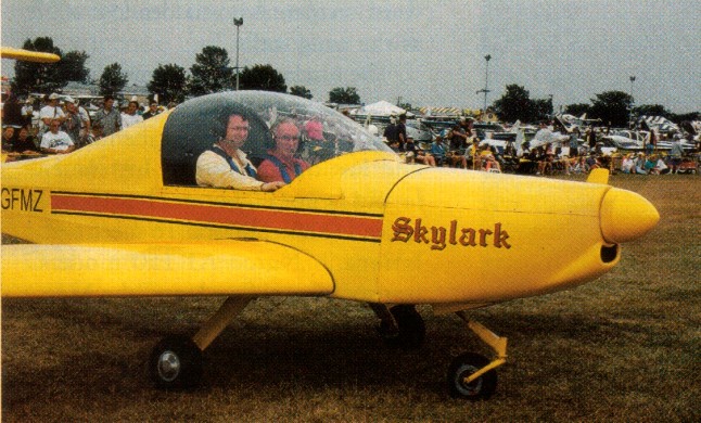
Design of the all metal, T tail, side by side two place Skylark began in January 1999, with the first flight on 10 March 2000. After the first flight, all that was required was a change to the incidence on the horizontal tail.
The Skylark is basically a 6061-T6 aluminium structure aircraft with 0.016 2024-T3 Alclad in the control surfaces. Winglets, engine cowling, tips and main landing gear legs are composite. The wing is tapered with the same wing section across the entire span. A channel type spar, located at 38% chord, is 9 in high and reinforced at the root. It tapers to 7 in at the tip. Each wing panel is fitted with six ribs stamped from 0.025 in 6061 sheet and has three full span skins. Wings are bolted to the fuselage carry-through spar.
Seven foot span, 7.25 in flaperons actuate the flap function mechanically by a handle below the centered throttle quadrant. They reflex (move up) 10 degrees for cruise.
The wing employs an IARV 419 airfoil that was designed by Stephen Marsden. It is a high lift, laminar flow profile specifically designed not to be sensitve to surface roughness due to ice, rain, and snow.
The fuselage is a semi-monocoque structure with three formers aft of the cockpit, which is 43 in wide and has dual controls. A 4.25 cu.ft baggage area is behind the seats. The stabiliser and elevator have a 9 ft span each. A 48 in electrically operated trim tab is installed on the left side of the elevator. The fin is reinforced at the root. Rudder height is 50 in. All of the tail control surfaces are D-cell structures with ribs but no spars. The elevator has six ribs, and the rudder has three.
Main gear legs carry Cleveland wheels and brakes, with 5.00×5 McClreary tires. The nosegear castors, employing a 4130 square steel leg with a spring shock absorber and a 5.00×4 Lamb tire. Main gear tread is 79 in, and wheelbase is 48 in.
Two 14.5 USG welded aluminium fuel tanks are located behind the wing spar, starting at the root and extending 35 in.
Skylark has double tip winglets. As part of the development program, a single winglet was added after the first flight, positioned at the front of the tip. It did assist tip airflow and split the vortices in two parts. Marsden deduced that dual winglets would work better. He added a second winglet, canted out at 45 degrees, that splits the vortices into three parts. This increased effectiveness about 50% over the single winglet.
For takeoff, flaps are set 10 degrees down. On approach, 20 degrees flap are set for landing for better visiblity. The aileron differential is 10 degrees up and 15 degrees down from whatever the flap angle is set.
Downwind approach is at 80 mph, reducing to 70 on base and final, with a touchdown speed of 54 mph.
Engine: Rotax 912, 80 hp
Prop: CSC wood, ground adjustable 68 in
hp range: 85-150
Wingspan: 22 ft
Wing chord: 48 in
Wing area; 92 sq.ft
Empty weight; 655 lb
MAUW: 1200 lb
Fuel capacity: 2 x 14.5 USG
Max level speed; 130 mph
Stall 20 deg flap: 50 mph
Cruise 75%: 120 mph
Fuel burn at 75%: 4 USGph
Econ cruise: 90 mph
Fuel burn at econ cruise: 2.5 USGph
Stress: +6 / -4
Takeoff run; 500 ft
Takeoff speed: 52 mph
Climb rate: 650 fpm at 75-80 mph
Vne: 210 mph
Range at 120 mph: 700 mile
Landing distance: 500 ft
Marsden Gemini
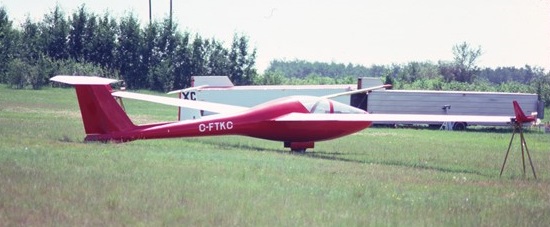
(courtesy Bruce Friesen)
Designed by David Marsden and built by Marsden, E. Dumas and M.D. Jones, the side-by-side two-place Gemini, which flew in 1973, has a genuine variable geometry planform. Marsden, who successfully modified the British Operation Sigma Type C variable geometry glider, used a number of the Sigma features in his design. It has full span 35 % chord Fowler flaps which are extended when climbing and retracted when cruising. When extended, a high maximum coefficient of lift of 2.2 is achieved, giving a good climb performance. The flaps also deflects to 80 degree for approach control. It has slotted ailerons for improved roll control.
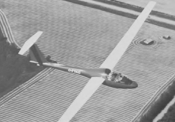
First flying in October 1973, during the 1970’s the Gemini set seven Canadian multi-place records, including the 500 km speed triangle.
The Gemini is all metal except for GFRP forward fuselage; stainless steel ribs, fittings and control system.
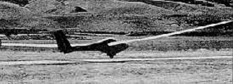
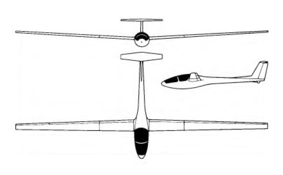
Wing span: 18.5 m / 60.75 ft
Wing area: 11.52 sq.m / 124 sq.ft
Length: 7.77 m / 25 ft 6 in
Height: 1.52 m / 5 ft 0 in
Empty Weight: 356 kg / 785 lb
Payload: 220 kg / 455 lb
Gross Weight: 576 kg / 1240 lb
Wing Load: 50 kg/sq.m / 10 lb/sq.ft
Water Ballast: 0
Stalling speed: 35 kt / 65 km/h
L/D Max: 40 at 119 kph / 64 kt / 74 mph
Best glide ratio: 38 at 60 kt / 110 km/h
Min Sink: 0.63 m/s / 2.08 fps / 1.23 kt
Min sinking: 0.75 m/sec / 2.46 ft/sec at 43 kt / 80 km/h
Aspect ratio: 29.8
Airfoil: Wortmann FX-61-163/35SF mod.
Seats: 2
No. Built: 1
Marsden, David
The senior Marsden taught aeronautical engineering at the University of Alberta, Edmonton, Canada, retiring in 1994.
Aeronautical Engineering Research Inc, 3920 Aspen Drive West, Edmonton, Alberta, Canada T6J 2B3.
Mars Skylark
The Philippines can claim south-east Asia’s earliest encounter with manned powered flight, when American aviator James C. “Bud” Mars thrilled spectators in his Skylark pusher biplane (a modified Curtiss design) at the Manila Carnival on February 21, 1911. Mars was part of a Pacific Aviation Exhibition tour organised by fellow American Capt Thomas Baldwin, who followed Mars’s Skylark display at the Carnival with a demonstration of his own Baldwin Red Devil, the pair having arrived with their dismantled aircraft aboard a steamer from Hawaii ten days previously. The exhibition had not gone so well in Hawaii, where the locals had quickly established a principle that has caused headaches for airshow organisers ever since; why pay for a ticket to enter the showground when you can see an air display from any nearby vantage point? The Manila Carnival organisers must have found a way to sidestep this issue, as the pair of aviators made numerous flights during the week-long festival. Baldwin sold his machine before the duo moved on to complete the Pacific tour with visits to Thailand, Hong Kong and Japan.
A replica of the Mars Skylark built by students at the Philippine Air Transport & Training Services College of Aeronautics in 2011 now hangs in the Philippine Air Force Museum at Villamor Air Base near Manila.
Mars Fokker E-III
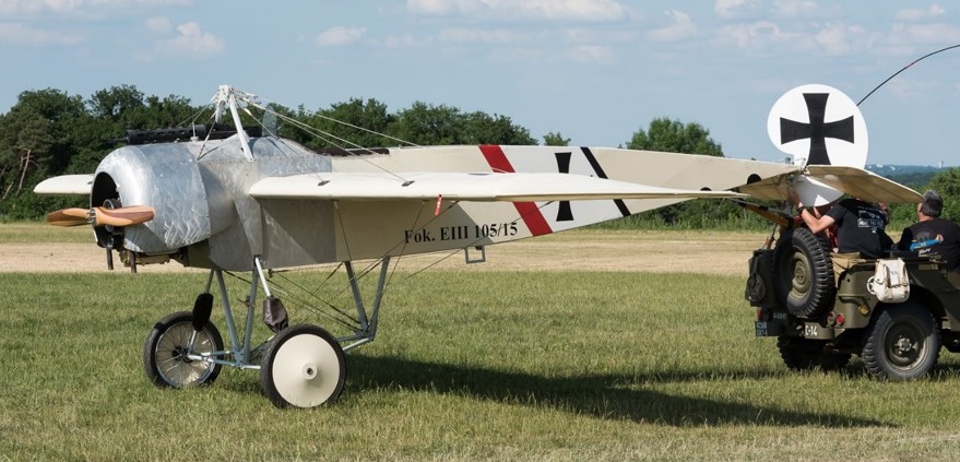
Hubert Mars built a replica Fokker E.III circa 2017 in France.
Marquart MA-5 Charger
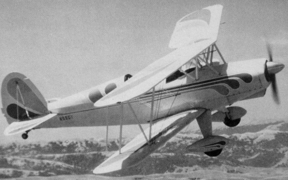
Designed by Ed Marquart and built with Dan Fielder, the Charger first flew in 1970, stressed for +6 to -4.5G’s. Gear tread is 6.5ft, making for easy ground handling. Wings are built around solid spruce spars and trussed spruce ribs, covered with ceconite. Engine 115-116 hp.
Engine: Lycoming O-290 125hp @ 2600rpm.
HP range: 125-180.
Length: 19ft 6in.
Wing area: 176 sq.ft.
Wing span: 24 ft.
Height: 7 ft.
Empty wt: 1000 lbs.
Payload (less std fuel): 438 lbs.
Wheel base: 14ft.
Wheel track: 6 ft.
Baggage cap: 25lbs.
Max level speed: 120mph (approx).
Cruise: 116 mph.
Stall: 45mph.
Best climb rate: 1100 fpm.
Range: 400 sm.
Take-off dist: 600 ft.
Landing dist: 700 ft.
Service ceiling: 13,000 ft.
Gross: 1550 lbs.
Seats: 2.
Landing gear: tail wheel.
Fuel cap: 27 US Gal.
Marquart MA-4 Lancer
A single-seat biplane
Marquart
Edward Marquart designed the MA-4 Lancer single-seat biplane and MA- 5 Charger two-seat aerobatic biplane, made available in plans form.
1996: Box 3032, Riverside, CA 92519-3032, USA.
Markwalder Marabu
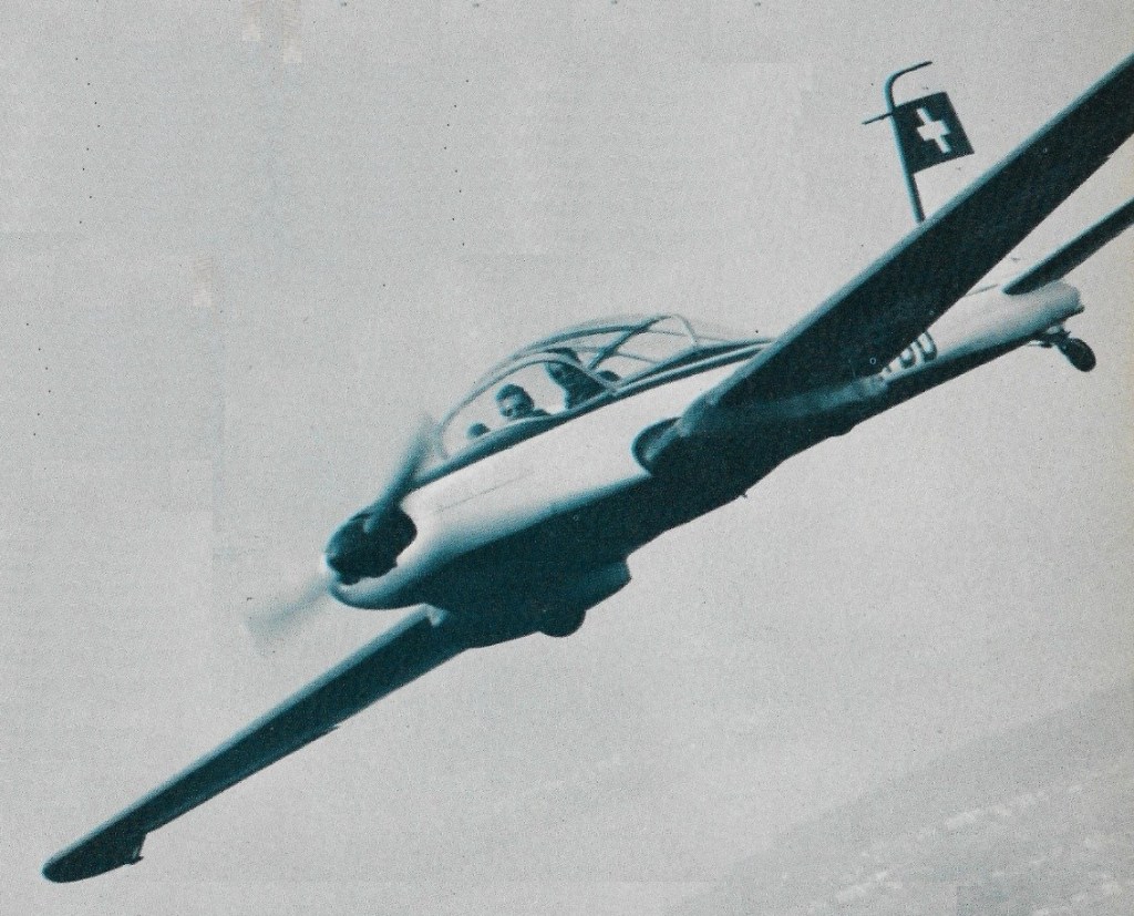
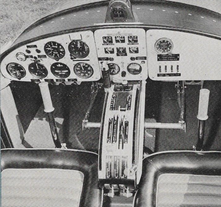
Designed by Ing. Albert Markwalder and built by Enst Bärfuss circa 1968, the Markwalder Marabu is an all-wood three seater featuring plywood skin over the entire structure. The cantilever wing houses four aluminium/polyester fuel tanks. Wing root fillets and wingtips are of moulded fibreglass the vortex-control tips modelled after those on the Cessna 210. Airfoil at the wing root is an NACA 23012, tapering to NACA 23006 at the tips. Flaps lower to 60 degrees.
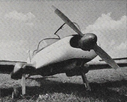
The retractable landing gear is manually operated, swings aft into ‘blisters’ under the wings, leaving the tires partially exposed to reduce damage in the event of a gear up landing.
Plans were not offered for sale.
Engine: Lycoming O-320, 150 hp
Prop: Hartzell VP 74 in
Max level speed: 171 mph
Cuise: 152 mph
ROC: 985 fpm
Empty weight: 1430 lb
MAUW: 2200 lb
Wingspan: 31 ft 10 in
Length: 24 ft 3 in
Height: 6 ft 7 in
Fuel capacity: 150 lt / 39.6 USG
Wing area: 150 sq.ft