1998:
Redland Airfield
Lower Wanborough
SN4 0AA Swindon
United Kingdom
Engine builder
1998:
Redland Airfield
Lower Wanborough
SN4 0AA Swindon
United Kingdom
Engine builder
First flown in 2003, piloted by Don Fleming, at Timaru.
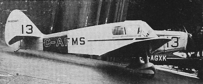
In 1938 the open-cockpit M.A.2 was completed, powered by Cirrus Minor, and later converted to cabin version.
Two models M.A.3 were completed, of wooden construction with plywood covering.
Engine: 90 hp Cirrus Minor
Wingspan: 34 ft
Wing area: 154 sq.ft
Length: 23 ft 3 in
Height: 7 ft
Empty weight: 880 lb
Loaded weight: 1400 lb
Max speed: 120 mph
Cruise: 105 mph
ROC: 850 fpm
Range: 400 mi
A two-seat cabin monoplane was built 1937. Powered by Pobjoy Niagara III engine, it was converted to open cockpit configuration 1938.
Formed in 1936 at Chorley, Lancashire, where prototype M.A.1 two-seat cabin monoplane was built 1937. Powered by Pobjoy Niagara III engine, it was converted to open cockpit configuration 1938. Following year open-cockpit M.A.2 completed, powered by Cirrus Minor, and later converted to cabin version.
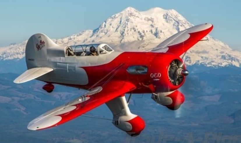
In 2002, aircraft builder Jim Moss set out to recreate the Gee Bee QED. Starting with the basic original plans, Moss’ recreation incorporated several modifications including wider landing gear, lengthened wings, a 20% larger vertical fin, and the installation of a 1425 hp. Wright R-1820 engine which replaced the original 650 hp. P&W R-1690.
The construction of the QED II took place between 2002 and 2013 and encompassed in excess of 50,000 man hours to build.
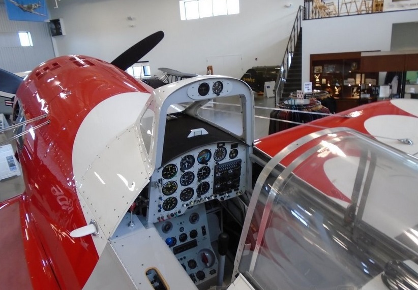
The aircraft was advertised for sale at $499,000 in October 2021.
Wright R-1820-56, 1425 hp
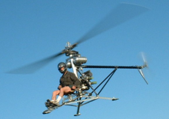
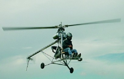
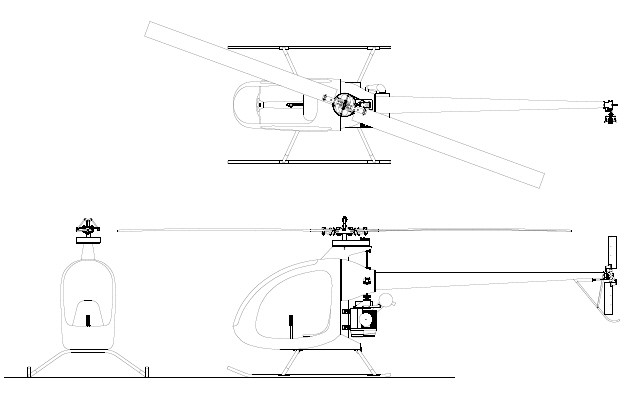
The ultralight Mosquito is one of the worlds lightest manned Helicopters that was designed and developed over 10 years to deliver performance, relability and easy of flight. The original prototype has been flying since 1994 and meets the ultralight Part 103 requirements.
The Mosquito frame is made up of Aircraft Grade 6061-T6 aluminum and utilises a simple triangulated structure with straight tubing throughout to maximize strength, reduce weight and simplify construction. The additional use of a Carbon Fibre tail boom and support struts adds to the Mosquito’s structural ridgidity. The Mosquito’s tripod legs are equiped with small skid pads to help reduce lateral movement during engine run-up to lift off stage. Ground handling wheels are also available to easy ground transport.
The Mosquito is powered by Compact Radial Engine’s – MZ202, 60-hp, a two cycle, two cylinder engine. This engine empolys Reed Induction which yields a very flat torque curve ensuring power is delivered constantly over the required operating range. The MZ202 also has a lower operating speed of 6000 rpm resulting in less stress on the engine and improving reliability. The complete engine package only weighs 69 pounds and comes with a 180-watt alternator that provides power to run the electrical system which also features and an electric start system.
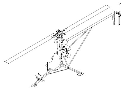
The primary reduction is bolted directly to the engine. A centrifugal clutch on the engine crankshaft permits startup of the engine without the load of the rotor. Power is transmitted from the clutch to the driven pulley of the reduction through an HTD cog belt. The driven pulley houses the sprage clutch, which permits the rotor to overspeed the engine during autorotation.
The Mosquito XE is the same aircraft, but the open frame tubing has been replaced with an all fiberglass closed in design. The XE airframe is a unibody construction made entirely of high quality fiberglass in a vinylester matrix. Power is provided by the same Compact Radial Engines MZ202 used for years on the open version of the Mosquito. This two cylinder, two stroke engine has a power output of 60hp, ample to do the work for its 610lbs of gross weight.
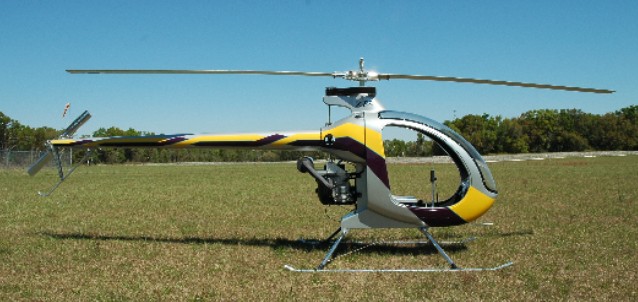
The power train, controls and rotor systems have been through some minor modifications to suit the XE design. The collective control has been adjusted to adapt to the different mounts in the XE. The main rotor blade diameter has increased by 1.5 ft to account for the additional gross weight. The Mosquito XEL is the same as the XE but is equipped with floats.
Materials provided with the kit include fiberglass airframe parts, machined parts, instruments (Rotor/Engine Tach, redundant digital engine tach with hour meter, dual EGT/CHT, Airspeed Indicator), rotor blades and engine. Many of the airframe parts are already joined. The builder needs only to bolt and rivet the final major components together.
A comprehensive assembly manual is provided along with a full set of part and assembly drawings as well as exploded view drawings. Builder assistance can be provided by phone or email. It requires around 250 to 300 hours of build time. Standard shop tools are required to cut and form some of the simple frame and control parts and for bolt and rivet assembly. A quick build parts set, in which all the parts nomally fabricated and formed by the builder are already finished, is available to save more build time. A small amount of welding is required on the exhaust system.
Optional extras to consider with purchase of the Mosquito include factory paint, tail fins, ceramic pistons, seat covers, governor kits, wheel kits and quick build parts.
The Mosquito XE can be ordered in several stages of kit. The 1st kit includes the materials and components for building the composite airframe. This group consists of the composite enclosure, fuel tank, tail boom, landing gear and the full Builder’s Set of Plans and Instructions. The kit is designed to meet the 51% rule.
The 2nd kit is for the cyclic, collective, torque tubes, push-pull tubes, swash plate, and rotor controls.
The 3rd is the power drive system consisting of primary and secondary reduction units, sprague clutch, engine coupling shafts, tail rotor drive shaft components, gear boxes, main rotor shaft assembly, and associated bearings, couplings, etc. and the 4th group includes the engine, battery, centrifugal engine clutch, fuel tanks, fuel valves, fuel lines, throttle, switches, wiring, and instruments.
The final stage is the assembly of the rotor heads, the tail rotor blades, and main rotor blades but the manufacturer likes to see you have some training under your belt before finishing this stage and being tempted or hurried to get airborn.
Delivery on complete kits is around 6 months from placing a deposit, or around 2 months for a kit group, depending on factory demand at the time.
Total Kit Price: US$17,495 after US$2,000 training rebate in 2009.
Mosquito
Engine: Compact Radial Engines MZ202, 2 cylinder, 2 stroke, 60 HP (45kW)
Frame Length: 16 ft.
Overall Length: 20 ft
Width: 72 in.
Height: 83 in
Main Rotor Diameter: 18 ft
Tail Rotor Diameter: 40 in.
Empty Weight: 254 lb.
Gross Weight: 530 lbs
Useful (Pilot) Load: 250 lbs
Fuel Capacity: 5 US gallons
Main Rotor Speed: 540 rpm
Tail Rotor Speed: 2500 rpm
Fuel Flow at Cruise: Approximately 4.5 U.S. Gallons per hour
Flight Duration: Approx. 60 min.
Hover in ground effect: 8,000 ft. (estimated)
Hover out of ground effect: 6,500 ft. (estimated)
Max Speed: 70 mph
Mosquito XE
Frame Length: 16 ft
Overall Length: 20 ft
Width: 72 in
Height: 84 in.
Main Rotor Diameter: 19.5 ft
Tail Rotor Diameter: 40 in.
Empty Weight XE: 298 lb
Gross Weight: 610 lbs
Useful (Pilot) Load: 240 lbs.
Fuel Capacity: 12 US gallons
Engine: Compact Radial Engines MZ202, 2 cylinder, 2 stroke 64 HP (45kW)
Electrical System: 12 volt DC battery, starter, 180 watt alternator
Main Rotor Speeds: 540 rpm
Tail Rotor Speeds: 2500 rpm
Fuel burn: 4.5 gph
Range: 150 miles
Hover in ground effect: 8,000 ft. (estimated)
Hover out of ground effect: 6,500 ft. (estimated)
Max Speed: 80 MPH
Price: $30,000 including engine/instruments (2009)
Mosquito XEL
Frame Length: 16 ft
Overall Length: 20 ft
Width: 72 in
Height: 84 in.
Main Rotor Diameter: 19.5 ft
Tail Rotor Diameter: 40 in.
Empty Weight XEL: 312 lb
Gross Weight: 610 lbs
Useful (Pilot) Load: 240 lbs.
Fuel Capacity: 5 US gallons
Engine: Compact Radial Engines MZ202, 2 cylinder, 2 stroke 64 HP (45kW)
Electrical System: 12 volt DC battery, starter, 180 watt alternator
Main Rotor Speeds: 540 rpm
Tail Rotor Speeds: 2500 rpm
Fuel burn: 4.5 gph
Range: 60 miles
Hover in ground effect: 8,000 ft. (estimated)
Hover out of ground effect: 6,500 ft. (estimated)
Max Speed: 80 MPH
Price: $31,000 including engine/instruments (2009)
Mosquito XE3
Frame Length: 16 ft
Overall Length: 20 ft
Width: 72 in
Height: 84 in.
Main Rotor Diameter: 19.5 ft
Tail Rotor Diameter: 40 in.
Empty wt: 360 lb
Gross wt: 720 lb
Useful load: 290 lb
Fuel Capacity: 12 gal
Range: 150 miles
Cruise spd: 80 mph
Max spd: 100+ mph
Fuel burn at cruise: 5 gph
Engine: CRE MZ301 3 cyl 2 cycle
Power 85 hp
Main Rotor RPM: 590
Tail rotor rpm: 2500
Hover in ground effect 9500 ft (est)
Hover out of ground effect 7500 ft (est)
Price: $36,000 including engine/instruments (2009)
Mosquito XET
Frame Length: 16 ft
Overall Length: 20 ft
Width: 72 in
Height: 84 in.
Main Rotor Diameter: 19.5 ft
Tail Rotor Diameter: 40 in.
Empty wt: 433 lb
Gross wt: 820 lb
Useful load (with optional aux tank): 240 lb
Useful load (without optional aux tank): 290 lb
Fuel capacity: 12 gal
Aux tank capacity: 8 gal
Range (with aux tank): 160 miles
Cruise spd: 80 mph
Max spd: 100+ mph
Fuel burn at cruise: 8.5 gph
Engine: Solar T62-2A1 turbine
Power: 90 hp
Main Rotor RPM: 590
Tail Rotor RPM: 2500
Hover in ground effect 9000 ft (est)
Hover out of ground effect 7000 ft (est)
Price: $37,000 excluding engine (2009)
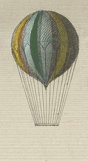
Frenchman M. Mosment did not use the customary basket on his balloon, but stood on a flat platform. He made his last ascent at Lille on 7th April, 1806. About ten minutes after takeoff a small parachute, containing some animal, was observed to be launched from the car; immediately afterwards an object which was soon ascertained to be the flag of the adventurer, slowly followed it through the sky. A rumour began to spread about that the aeronaut himself had fallen from his balloon. This was shortly after confirmed by the discovery of his body almost buried under the sand in one of the fosses (ditches) of the ramparts that surrounded the town. It was supposed that the oscillations communicated to the balloon in the act of delivering the parachute had thrown him off his balance. Some persons pretended at the time to have heard him declare the event before-hand, and from thence argue that the affair was not unpremeditated.

The engine was progressively developed designed around Volkswagen air-cooled engine components. Global Motors originally designed a 1/2 VW engine for use in light aircraft. The company and its designs were then sold to Mosler Motors. Warren Mosler specialized in racing engines and added the engine to the list of products eventually marketed under the company name Total Engine Concepts.
The CB-40 was re-engineered to overcome problems of vibration and cooling in the original design. In order to improve oil circulation a new oil sump, professionally designed and CNC manufactured was added. Prepared for carb heat and cabin heat.

Suited for ultralight use and single seat light sport aircraft, the engine weighs 86 lbs and produces 40 hp (30 kW). The engine uses a short aluminum crankcase with redesigned oil galleries for improved lubrication. The engine is counterweight balanced with a drop-forged crankshaft.
The engine was dropped from production in 1998.
Variants:
TEC CB-40
Base model 40 hp (30 kW).
TEC CB-35
35 hp (26 kW) variant with a shorter stroke.
Specifications:
TEC MM CB-40
Type: 2-cylinder air-cooled horizontally opposed aircraft piston engine
Bore: 3.701 in
Stroke: 3.071 in
Displacement: 66.1 cu.in
Dry weight: 86 lbs
Fuel type: 100LL avgas
Cooling system: Air-cooled
Power output: 40 hp at 3250 rpm at sea level
Compression ratio: 8.94:1
Mosler CB40
2 Cylinder 4-stroke
Power: 40hp/3200rpm
Weight: 40kg
Displacement: 1100cc
TBO: 1000hr
Ignition: Magneto Fairbanks
Fuel cons: 4-5 L/hr
TEC ½ VW
Cycle: 4 stroke
No cylinders: 2
Compression: 9
Displacement: 1024 cc
Cooling: Air
Ignition: Electronic
Reduction: 3.5/1 mechanical
Dimension: 540 x 740 x 590 mm
Weight: 74 kg
Max pwr: 90 hp at 7250 rpm
Max torque: 90 at 5000 rpm
Fuel consumption: 240 G/kw/hr
Price 1998: 13 000 DM

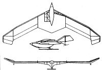
In 1970, following studies carried out by Alexei Ivanovich Pietsuj’s group in relation to tailless gliders, student VP Pushkin carried out a project of a new model with this configuration. It was a development of the concept outlined with the previous MAI-63. Named MAI-68 it was nicknamed “Pushinka” (Russian: МАИ-68 «Пушинка») in honour of its designer.
Professors GS Sadiekov, LA Matvieyev and VI Figurovski participated in the process of creating the new model. The general direction was in charge of AI Pitsuj.
The glider was designed as a single-seater basic training device in order to be able to compare its performance to those of similar models with the classic scheme. It was decided to apply an integral construction in which the fuselage, wings and tail were fused into a single structure.
The construction was metallic with fabric covering. The structure of the glider was built with aluminum profiles.
The aircraft featured a fluted wing with variable thickness and variable line of lights along the wingspan as well as the long arm of the steering and rudders.
The selected wing profile was the R-Sh with a constant thickness of 15.5 throughout the wingspan. The force structure is composed of two spars of similar thickness between which the wing ribs were located. The wing leading edge was coated with 0.5 mm thick duralumin sheets.
The wing shape, in conjunction with the K-shaped structure of the short wing-end stabilizers, ensured the necessary longitudinal and lateral stability as well as good manoeuvrability. The location of the wing-end stabilizers had a positive influence on wing flow, significantly reducing the creation of vortices in this area.
Single-spar ailerons were attached to the wing structure at three points.
The alligator-type wing-end rudders ensured longitudinal control if operated integrally. When operating the pedals, these surfaces were opened independently, acting as aerodynamic brakes. By operating a single pedal, the resistance at this wing end allowed control of the rotation of the apparatus.
The control system was operated by cables.
The landing gear consisted of a main wheel with a front ski and stabilization straps on the wing.
The cabin, for a single crew member, had a well-equipped instrument panel with an airspeed indicator, altimeter, artificial horizon and variometer. The transparent cover had an opening to the right. To improve downward visibility, the lower nose region and forward fuselage were coated with clear acrylic.
The MAI-68 experimental glider was built by V. Pushkin between 1968 and 1970. Ground tests began in July 1970, which were followed by flight tests at the MAI aeroclub aerodrome.
The test flights were developed by club director IG Yermakov. The “Hercules III” series tensioner was used for the launch.
During the ground tests it was possible to verify the effectiveness of the rudders, as well as the good stability and ease of control of the glider. The first short flights showed an acceptable longitudinal and transverse stability, as well as a marked delay in the reaction of the rudders. To eliminate this phenomenon, the opening surface of the elevator shafts was increased, achieving an increase in the effectiveness of these structures and allowing the development of the first flights at heights of 250 – 300 meters.
Tests of the glider at the MAI continued until 1972. In total they comprised 12 jumps at heights of 1 – 2 meters from the ground, 26 flights at 40 – 70 meters and four flights at 250 – 300 meters. A towed flight was made by a Yakovlev Yak-12.
The tests were continued at the TsAGI between 1973 and 1974. The flights, carried out by VN Vladimirov, were carried out at the Glider Station airfield. At this stage it was possible to measure the benefits and develop a series of mathematical models that verified the coincidence with the project calculations.
It was possible to establish a minimum glide speed of 45 km / h and an aerodynamic quality of 21. The effectiveness of the large lower surface of the center plane during takeoffs and landings was highly valued.
After testing the MAI-68, its designer VP Pushkin worked in the aeronautical industry and in this period he designed and built two other devices with this scheme, which showed excellent indicators and performance.
MAI-68 Pushinka
Wingspan: 10.00 m
Wing area: 10.2 m²
Aspect ratio: 8.54
Length: 5.00 m
Empty weight: 86 kg
Normal weight: 170 kg
Wing loading: 16.7 kg / m²
Minimum speed: 45 km / h
Maximum glide ratio: 21
Accommodation: 1