Train 6T

The Train 2T, 4T and 6T were all low power piston engines for light aircraft, produced in France. They were inverted, air-cooled in-line engines with the same bore and stroke, differing chiefly in the number of cylinders.

In the 1930s Train introduced a series of air-cooled, inverted in-line piston engines for light aircraft. The T series all used the same cylinders, pistons, connecting rods, valve trains and ignition system, combined into 2 (2T), 4 (4T), and 6 (6T) cylinder units of the same layout. The number of crankshaft bearings (3, 5 or 7) and throws (2, 4 or 6) naturally depended on the number of cylinders, as did the number of cams (4, 8 or 12) on the underhead camshaft. Each cylinder had a swept volume of 0.5 l (30.5 cu in), so the displacements were 1 l (61.0 cu in), 2 l (122.0 cu in) and 3 l (183.1 cu in) and the rated outputs 15 kW (20.1 hp), 30 kW (40.2 hp) and 40 kW (53.6 hp) respectively. The Train 6D was a variant of the 6T with increased bore of 85 mm (3.3 in).

Variants:
Train 6T
6-cylinders, 80 mm (3.15 in), 3 l (183.1 cu in), 40 kW (53.6 hp)

Train 6D
6-cylinders, 85 mm (3.35 in), 3.4 l (207.5 cu in), 62 kW (83.1 hp)

Applications:
Aubert PA-20 Cigale
Kellner-Béchereau EC.4
Kellner-Béchereau ED.5
SECAT S.4 Mouette
Volland 10

Train 4

The Train 2T, 4T and 6T were all low power piston engines for light aircraft, produced in France. They were inverted, air-cooled in-line engines with the same bore and stroke, differing chiefly in the number of cylinders.

In the 1930s Train introduced a series of air-cooled, inverted in-line piston engines for light aircraft. The T series all used the same cylinders, pistons, connecting rods, valve trains and ignition system, combined into 2 (2T), 4 (4T), and 6 (6T) cylinder units of the same layout. The number of crankshaft bearings (3, 5 or 7) and throws (2, 4 or 6) naturally depended on the number of cylinders, as did the number of cams (4, 8 or 12) on the underhead camshaft. Each cylinder had a swept volume of 0.5 l (30.5 cu in), so the displacements were 1 l (61.0 cu in), 2 l (122.0 cu in) and 3 l (183.1 cu in) and the rated outputs 15 kW (20.1 hp), 30 kW (40.2 hp) and 40 kW (53.6 hp) respectively.

Several International 2-litre Class records were set in 1937 by aircraft powered by the Train 4T. On 7 June 1937 M. Duverene averaged 96.0 mph; 83.4 kn (154.5 km/h) 154.5 km/h (96.0 mph; 83.4 kn) over 1,000 km (621.4 mi; 540.0 nmi) and 95 km/h (59.0 mph; 51.3 kn) over 1,000 km (621.4 mi; 540.0 nmi) in a single engine Kellner-Béchereau E.1. On 27 December 1937 Mme Lafargue reached an altitude of 4,935 m (16,191 ft) in a Tonya, setting both a class and a women’s record.

It also powered aircraft on some notable cross-country flights; on 30 December 1937 M. Lenee flew a Kellner-Béchereau E.1 from Elde to Biarritz, a distance of 1,229 km (763.7 mi; 663.6 nmi); the same day M. Blazy flew a two seat SFAN aircraft from Guyancourt to Champniers, Charente, covering 330 km (205.1 mi; 178.2 nmi).

Six Train 4Ts were used in the 2 seat, 18 m (59.1 ft) span Potez-CAMS 160 flying boat, a 1:2.6 scale model of the large Potez-CAMS 161 aircraft.

Variants:
Train 4T
4-cylinders, 80 mm (3.15 in), 2 l (122.0 cu in), 30 kW (40.2 hp)

Train 4A – variant of the 4T

Train 4E – variant of the 4T

Applications:
Brochet MB.50
Caudron C.344
Chilton D.W.1A
Druine Aigle 777
Kellner-Béchereau E.1
Mauboussin Hémiptère
Morane-Saulnier MS-660)
Nicolas-Claude NC-2 Aquilon
Payen AP-10
Potez-CAMS 160
SFAN two seater
Tonya aircraft
Trébucien Sport

Specifications:
4T
Type: 4-cylinder inline inverted air-cooled
Bore: 80 mm (3.15 in)
Stroke: 100 mm (3.94 in)
Displacement: 2.01 L (123 in3))
Length: 670 mm (26.4 in)
Width: 240 mm (9.45 in)
Height: 516 mm (20.3 in)
Dry weight: 46 kg (101 lb)
Valvetrain: Valves directly operated by cams on underhead camshaft, driven from crankshaft via bevel gears. One inlet and one exhaust valve/cylinder.
Fuel system: single carburetter
Ignition system: Choice of one or two magnetos with one or two plugs/cylinder
Oil system: Pumped under pressure from external tank, feeding main bearings and big ends; little ends and piston walls spray fed. Gravity return. Underhead valve gear in full length oil bath.
Cooling system: air
Reduction gear: None
Cylinders: Machined steel barrels with aluminium-bronze heads containing machined valve seat and secured with long bolts to crankcase.
Pistons: Aluminium alloy. Floating gudgeon pins. Three compression and one scraper ring/cylinder
Connecting rods: Forged duralumin with split big ends.
Crankshaft: 4-throw steel casting with 5 white metal lined bearings. Front ball race thrust bearing.
Crankcase: Aluminium casting in top and bottom halves, with capped crankshaft bearings in the lower part.
Power output: Rated 30 kW (40 hp), actual 33 kW (44 hp), both at 2,300 rpm
Specific power: 16.5 kW/L (0.64 hp/in3)
Compression ratio: 6:1
Specific fuel consumption: 322 g/(kW·h) (0.529 lb/(hp·h))
Oil consumption: 61 g/(kW·h) (0.10 lb/(hp·h))
Power-to-weight ratio: 0.72 kW/kg (0.44 hp/lb)
Train 2T

The Train 2T, 4T and 6T were all low power piston engines for light aircraft, produced in France. They were inverted, air-cooled in-line engines with the same bore and stroke, differing chiefly in the number of cylinders.

In the 1930s Train introduced a series of air-cooled, inverted in-line piston engines for light aircraft. The T series all used the same cylinders, pistons, connecting rods, valve trains and ignition system, combined into 2 (2T), 4 (4T), and 6 (6T) cylinder units of the same layout. The number of crankshaft bearings (3, 5 or 7) and throws (2, 4 or 6) naturally depended on the number of cylinders, as did the number of cams (4, 8 or 12) on the underhead camshaft. Each cylinder had a swept volume of 0.5 l (30.5 cu in), so the displacements were 1 l (61.0 cu in), 2 l (122.0 cu in) and 3 l (183.1 cu in) and the rated outputs 15 kW (20.1 hp), 30 kW (40.2 hp) and 40 kW (53.6 hp) respectively.

Train 2T
2-cylinders, 80 mm (3.15 in), 1 l (61.0 cu in), 15 kW (20.1 hp)

Train

Établissements E. Train
Courbevoie
France

In the 1930s Train introduced a series of air-cooled, inverted in-line piston engines for light aircraft. The T series all used the same cylinders, pistons, connecting rods, valve trains and ignition system, combined into 2 (2T), 4 (4T), and 6 (6T) cylinder units of the same layout.

Trago Mills SAH.1 Sprint / Orca Aircraft Ltd SAH-1 / Lovaux / FLS Aerospace Sprint

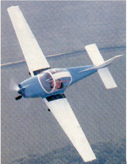
Trago’s boss, supermarket entrepreneur Mike Roberts, claimed to have already spent £1•25 million since he brought in chief designer Sydney Holloway in 1977 to build a trainer aimed at reversing the fortunes of British light aviation.
Holloway started work on the SAH.1 in 1977, build¬ing the aircraft in the living room of his home next to Bodmin airfield. Holloway’s wife Sheina did the drawings and put up with the mess. Holloway’s task was eased by the spon¬taneous help given by several skilled experts including Frank Robertson (no relation to Mike Robertson), who took over responsibility for the aerodynamic and stress calculations.

Holloway went for a strong but simple metal airframe, with the emphasis on minimum maintenance and easy repair. Unproven materials have been avoided, and PVC foam has been used for skin stabilisation to prevent “oil-canning”. The ailerons are of the slot¬ted Frise type, with differential action and external mass-balances. The slotted flaps, operated by means of a lever between the seats, incorporate built-in steps for easy entry.

With a 47 in cockpit, and a 14 cu.ft baggage bay behind the two folding and adjustable seats which can carry l00lb of baggage.

The SAH.1 can carry two l80 lb people and and two 12.5 Imp gal integral wing tanks full. It is cleared for aerobatics and spinning, and is stressed to +6g/-3g.

Orca Aircraft Ltd purchased the SAH-1 trainer from Trago Mills but went into administration in 1989. The SAH-1 became Sprint when purchased by Lovaux / FLS Aerospace. Lovaux Ltd was a subsidiary of FLS Aerospace for aircraft maintenance.

Powerplant: One 118 b.h.p. Avco Lycoming O-235-L2A
Prop: McCauley fixed-pitch, 5ft 6in diameter
Wing span: 30ft 8.4in
Length overall: 2lft 10.25in
Height: 7ft 7.5in
Cockpit length: 5ft
Cockpit width: 3ft 11.5in
Baggage volume: 14 cu.ft
Empty, equipped: 1,l00lb
Max take-off: 1,750lb
Max fuel load 25 Imp gal: 188 lb
Max wing loading: 14.581b/sq.ft
Never exceed: 164kt
Max level speed/sea level: 122kt
Cruise at 75% power/sea level: 110 kt
Service ceiling: 16,400ft
Take-off to 50ft (15 deg flap): 1,285ft
Range with 45mm reserve: 620 n.m.

Trager-Bierens Alibi T-3

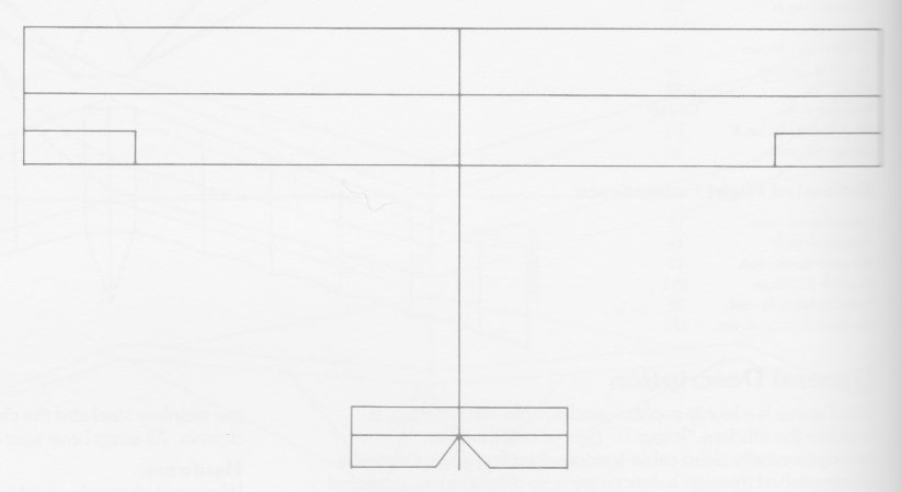
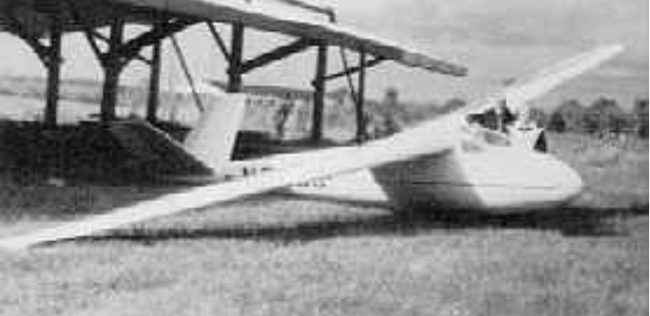
Designed by Kempes Trager and John Bierens, the T-3, which first flew in 1951, uses a set of Laister-Kauffmann LK-10A wings with a new all-metal fuselage with V-tail and retractable wheel. Later the wing was rebuilt and a new all-metal tail was incorporated.

Wing span: 15.24 m / 50 ft
Wing area: 13 sq.m / 140 sq.ft
Aspect ratio: 17
Airfoil: NACA 4418
Empty Weight: 227 kg / 500 lb
Payload: 113 kg / 250 lb
Gross Weight: 340 kg / 750 lb
Wing Load: 26.15 kg/sq.m / 5.1 lb/sq.ft
MinSink: 0.67 m/s / 2.2 fps / 1.30 kt
L/DMax: 28 77 kph / 42 kt / 48 mph
Seats: 1
No. Built: 1
Structure: wood/ fabric wings. Metal fuselage and tail.

Tradewinds Gliders TW-21

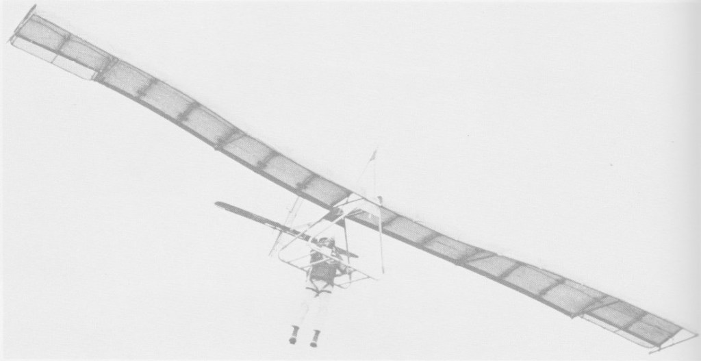
Circa 1972, the TW-21 is a fixed wing that has full three axis control, ailerons, rudder and elevators.

Stressed for 4.5G, all tubing is 6061-T6 seamless aircraft aluminium. Sizes from 5/8in to 1 5/8 in is used. Rigging cable is 3/32in 7×7 and 1 5/8 x .049 is used. All fittings and joints are heli-arc welded.

All bolts, nuts, turnbuckles, pulleys and brackets are aircraft quality. The sail options were 3.0 or 5.8 oz dacron, with a choice of 10 colours. All seams and stress areas are double zig-zag stitched and reinforced.

The TW-21 has fully adjustable seat harness and ground support straps, and an optional prone harness was available.

The control system and control stick are machined steel and welded.
Chord length: 4 ft 9 in
Wing span: 32 ft
Aspect ratio: 6.85
Nose angle: 0˚
Wing area: 153 sq,ft
Weight: 55 lb
Pilot weight: 110-220 lb
Takeoff speed: 12 mph
Stall speed: 14 mph
Max speed: 45 mph
Best glide ratio (L/D): 12:1
Best L/D speed: 26 mph
Min sink: 185 fpm

Chord length: 4 ft 9 in
Wing span: 34 ft
Wing area: 154.5 sq,ft
Aspect ratio: 7.55
Nose angle: 0˚
Weight: 71 lb
Pilot weight: 110-250 lb
Takeoff speed: 12 mph
Stall speed: 14 mph
Max speed: 45 mph
Best glide ratio (L/D): 12:1
Best L/D speed: 26 mph
Min sink: 185 fpm

Toyo Aircraft T-T.10

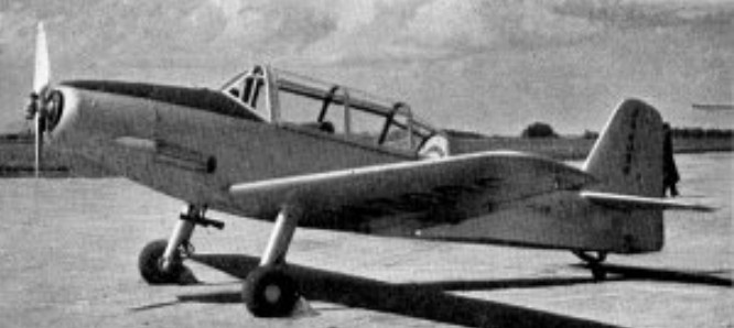
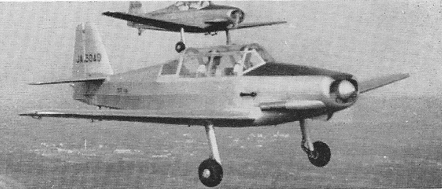
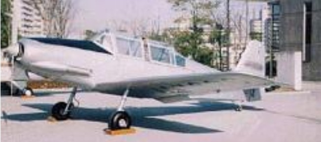
Toyo Aircraft was established in June 1952 and their first aircraft, the T-T.10 designed by Yoshio Hashiguchi, was completed by the end of the year. It is of mixed construction; the wing is built entirely from wood and fabric around two spars, with a plywood skin enclosed within fabric. The flaps and ailerons are wood framed and fabric covered. In planform the wings are straight tapered with rounded tips; most of the taper is on the trailing edge. There is 6 degrees of dihedral. The T-T.10’s tail surfaces are also straight tapered with rounded tips, generally wood framed with fabric covering. Its horizontal tail is mounted at the top of the fuselage. The elevators have a cut-out to allow rudder movement, as the latter extends down to the keel. There is a trim tab on the port elevator.

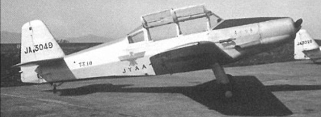
The fuselage of the T-T.10 is fabric covered over a welded chrome-molybdenum steel frame. The engine is a 140 hp (104 kW) Lycoming O-290-D2 flat four, driving a two bladed propeller. Student and instructor sit in tandem with dual controls under a multi-framed, continuous, two part sliding canopy. The rear fuselage line is raised compared with the forward section, but not to the full canopy height. The T-T.10 has conventional landing gear, with narrowly faired cantilever, coil spring damped mainlegs and a tailwheel.

The first T-T.10, registration JA3026, flew for the first time on 30 December 1952; the first production model (JA3049) followed soon after, on 11 February 1953. Production numbers are not known exactly; one report speaks of a “small batch” but only the first two T-T.10s appear in the single engine serial range JA3001 – JA3100, which covers the period August 1952 to September 1955, so they may constitute the whole batch.

One aircraft is on display at the Tokyo Metropolitan College F.A.M.E. Gallery: T-T.10 JA3026.

Engine: Lycoming O-290-D2, 100 kW (140 hp)
Propeller: 2-bladed Sensenich CSM3FM4/C374 fixed pitch
Wingspan: 8.60 m (28 ft 3 in)
Length: 7.15 m (23 ft 5 in)
Height: 2.10 m (6 ft 11 in) tail down
Wing area: 12.0 sq.m (129 sq ft)
Aspect ratio: 6.0
Airfoil: NACA 1415 at root, 2410 (modified) tip
Empty weight: 568 kg (1,252 lb)
Gross weight: 800 kg (1,764 lb)
Fuel capacity: 90 L (19.8 Imp gal; 23.8 US gal)
Maximum speed: 235 km/h (146 mph; 127 kn) at sea level
Cruising speed: 190 km/h (118 mph; 103 kn)
Stall speed: 80 km/h (50 mph; 43 kn) with 30° flaps
Service ceiling: 4,300 m (14,108 ft) service
Rate of climb: 3.8 m/s (750 ft/min) initial
Wing loading: 67 kg/sq.m (14 lb/sq ft)
Power/mass: 8.0 kg/kW (13.1 lb/hp)
Take-off distance to clear 15.25 m (50 ft): 290 m (950 ft)
Landing distance from 15.25 m (50 ft): 300 m (985 ft)
Crew: 2