Douglas C-124 Globemaster II

C-124C

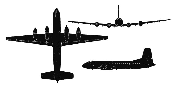
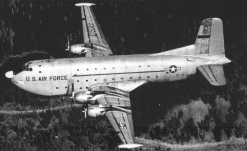
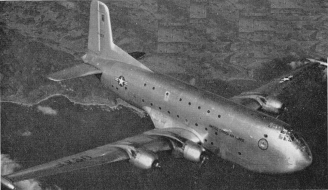
Although the production run of the C-74 Globemaster had been held to 14 airframes, the success of this oversized transport led the US Air Force and Douglas to agree upon construction of an improved long-range transport. The fifth C-74 airframe was used to create the service-test YC-124 Globemaster II which retained the earlier aeroplane’s wings, tail surfaces, and 2610kW R-4360-49 engines. The YC-124 flew on 27 November 1949. The new fuselage was double-decked and the aircraft had enormous clamshell loading doors at the nose with an associated built-in loading ramp, an electric hoist amidships, and two overhead cranes (each with a capacity of 7257kg which could traverse the entire length of the 23.47m-long cargo hold. When used in a transport role (with two decks installed), the Globemaster II could carry a maximum of 200 fully-equipped troops, or 123 stretcher cases plus 45 ambulatory patients and 15 medical attendants.

Douglas C-124 Globemaster II Article

A pre-production aircraft and 28 C-124A models were retrofitted with the ‘thimble’ nose fairing containing ASP-42 radar. Douglas then manufactured no fewer than 243 C-124C models, with the radome as standard, increased fuel, wingtip fairings housing combustion heaters to de-ice the wing and tailplane leading edges and to heat the cabin, and other improvements. The first service Globemaster began duty in May 1950, the month before the outset of the Korean War. Although production was finished by May 1955, the Globemaster II remained a standard in USAF service for years thereafter.
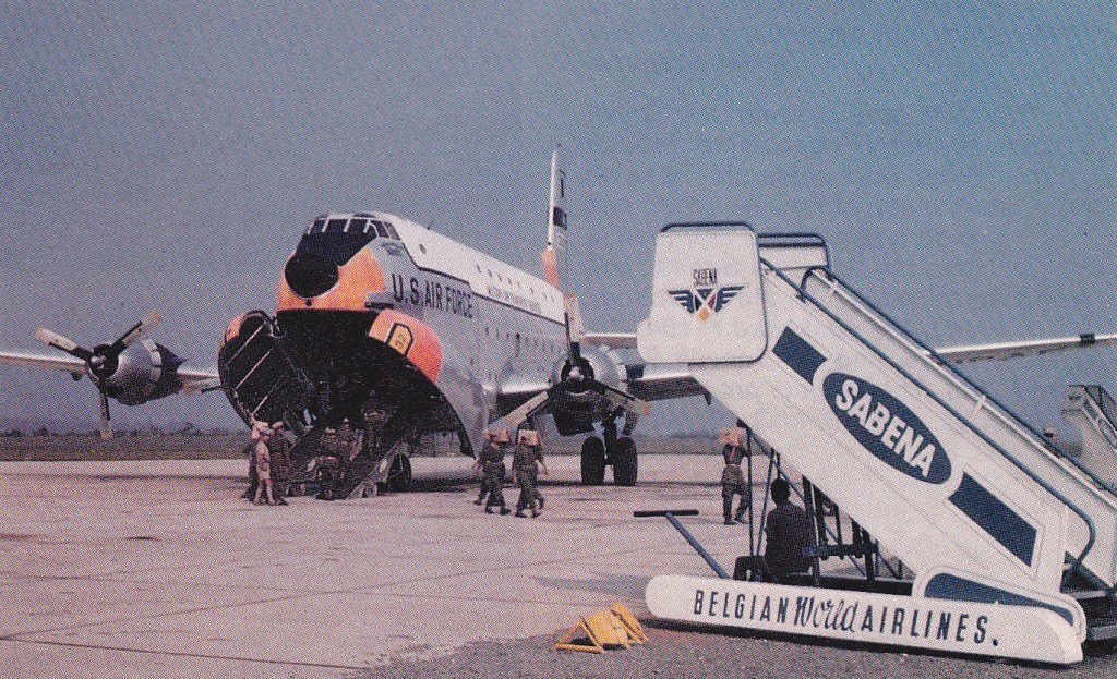
C-124C Globemaster II of 39th Air Transport Squadron flying supplies to Leopoldville in 1963

The Globemaster IIs remained in service until replaced by the Lockheed C-5A Galaxy during 1970.
The YKC-124B Globemaster II was Douglas’ bid for a major order for air refuelling tankers. In 1951, engineers began working on a C-124 airframe to be powered by 5,500-shp Pratt & Whitney YT34-P-1 turboprop engines. Gas turbine power produced a kind of ‘Super Globemaster II’ with greater speed, altitude and range capability than the ‘recip’ aeroplane but for reasons not now clear, the USAF decided instead to order the Boeing KC-97 Stratofreighter as its standard tanker even though the latter aircraft did not perform so well. By the time the turboprop Globemaster II flew on 2 February 1954, it had been redesignated YC-124B and was used for proof-of-concept evaluations. Though no orders resulted from its 32-month test programme, the YC-124B contributed substantially to knowledge needed when the C-133 Cargomaster came along.
Gallery

YC-124 Globemaster II
Engines: 4 x R-4360-49.

C-124A
Engines: Pratt & Whitney R-4360-20W, 3500 hp

YC-124B
Engines: 4 x 5,500 h.p. Pratt & Whitney T34-P-1 turboprops

C-124C Globemaster II
Engines: 4 x Pratt & Whitney R-4360-63A Wasp Major, 3800 hp / 2795kW
Wing span 173 ft 3 in / 53.1 m
Length 130 ft 5in / 39.8 m
Height 48ft 3.5in / 14.7 m
Wing area: 2,506sq.ft. / 233.0 sq.m
Empty weight: 101,165 lb.
Max weight: 194,5001b.
Max speed: 298 mph at 20,800 ft
Cruise speed: 520 km/h / 323 mph
ROC: 800 fpm
Service ceiling: 21,800 ft.
Range w/max.fuel: 6500 km / 4039 miles
Range w/max.payload: 1970 km / 1224 miles
Crew: 5
Passenger capacity: 200

Douglas 415 / C-74 Globemaster

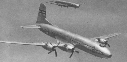
In 1942 Douglas began to design a larger, would-be successor to the Douglas C-54. The new model, identified in project form as the Model 415, had the same four-engine, low-wing layout as its predecessor, but it was about half again as large dimensionally and twice as heavy. With 3,250hp (2,420kW) Pratt & Whitney R-4360-27 Wasp Major engines, it would cruise at 296mph (476km/h), considerably faster than the C-54. The pilot and co-pilot were separately enclosed in side-by-side bubble canopies, an arrangement later found far from satisfactory from a crew communication standpoint. It was a cantilever low-wing monoplane of all-metal construction, with a conventional tail unit, and retractable tricycle landing gear with twin wheels on each unit.
The C-74’s fuselage provided accommodation for the crew and 125 troops, or 115 stretchers with medical attendants, or up to 21840kg of cargo.
Orders were received for 50 examples of a military version known as the C-74 Globemaster.
In 1945, Pan American Airways also recognized the new model’s potential and ordered 26 with seats for 108 passengers. As ‘DC-6’ was already assigned, the civilian version was called the DC-7. Unlike the C-54, the DC-7 was to have a pressurized cabin.
By the time of the first flight on September 5, 1945, the military order had been reduced to 14 units. One, with 103 passengers and crew, flown from the USA to the UK on 18 November 1949, was the first aircraft to fly across the North Atlantic with more than 100 persons on board.
With development costs shared by fewer military airplanes, the cost of the DC-7s rose accordingly. Pan American reassessed its needs, as well as the increased cost of the DC-7s, and elected to cancel its order altogether. Although the DC-7 failed as a civil airliner, Douglas did redesign the fuselage of the C-74 to create the C-124 Globemaster II.

Douglas B-23 / C-67 Dragon

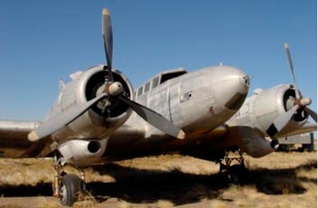
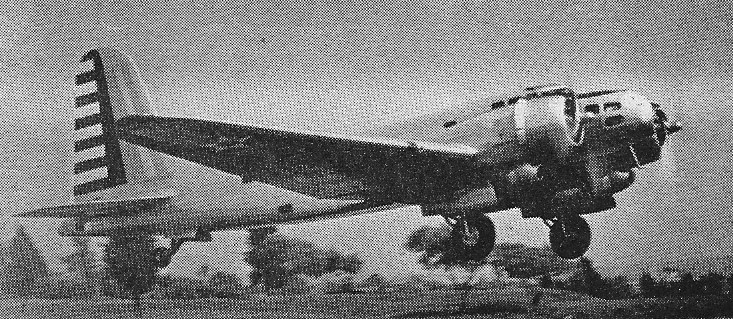
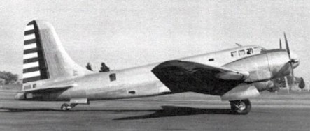
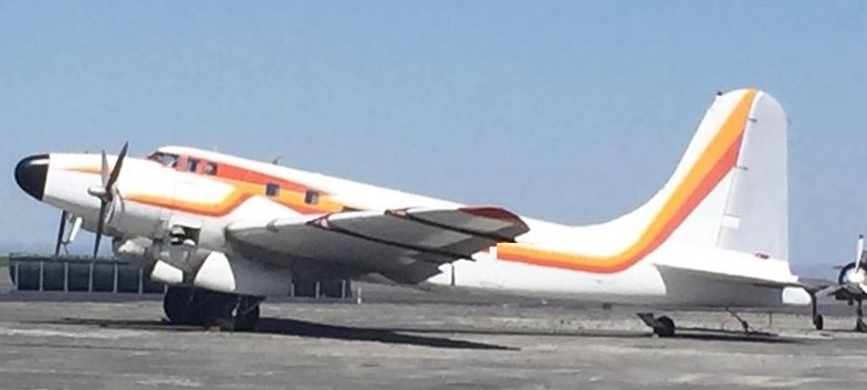
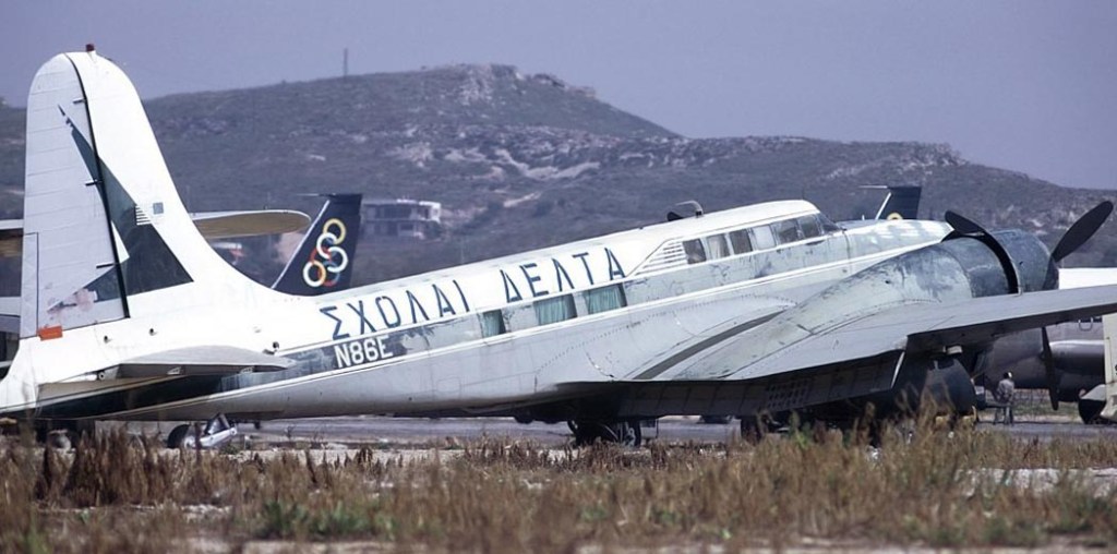
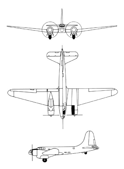
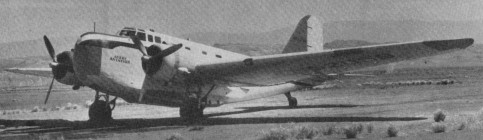
In an attempt to rectify the shortcomings of their DB-1 design, Douglas developed in 1938 an improved version and the proposal seemed sufficiently attractive for the US Army to award a contract for 38 of these aircraft under the designation B-23 and with the name Dragon.

Landing gear was retractable tailwheel type, but the engine nacelles had been extended so that when the main units were lowered in flight they were faired by the nacelle extensions and created far less drag.

The main difference was the switch to much more powerful engines (the most powerful then available), the 1450 hp Wright R 2600 1 Cy¬clone 14. The army adopted the proposal as the B 22, but soon switched to a further improvement designated B 23. The B 23 Dragon included the first US Army tail gun position, a hand aimed .03 in (12.7¬mm). Nose, dorsal and ventral positions each had one 0.30 in (7.62 mm). The tail wheel is offset to allow the tail gunner to access his position from the fuselage. Maximum bomb¬load was 2177 kg (4800 lb), all internal.

In the Fiscal Year 1939, a batch of 38 B 23 Dragons was funded, following successful trials with the prototype in the summer of 1939.

First flown on 27 July 1939, the B-23s were all delivered to the US Army during that year. Early evaluation had shown that performance and flight characteristics were disappointing. Furthermore, information received from the European theatre during 1940 made it clear that development would be unlikely to result in range, bombload and armament capabilities to compare with the bomber aircraft then in service with the combatant nations, or already beginning to emerge in the USA. As a result these aircraft saw only limited service in a patrol capacity along the US Pacific coastline before being relegated to training duties.

During 1942 about 15 of these aircraft were converted to serve as utility transports under the designation UC-67, and some of the remainder were used for a variety of purposes including engine testbeds, glider towing experiments and weapons evaluation. They were popular executive transports after the war.

Douglas UC-67 Dragon

A total of 38 examples were built, all powered by Wright R-2600 Cyclone engines.

Douglas UC-67 Dragon (C-67)

In 1963 Juan T. Trippe, Pan Am president flew in a B-23 owned by Pan Am, carrying no identification, flown by Pan Am pilots and based at Butler Aviation on LaGuardia. Trippe flew between New York and Washington regularly.

Gallery

B-23
Engines: 2 x Wright R-2600-3 Cyclone 14, 1193kW / 1578 hp
Max take-off weight: 13824 kg / 30477 lb
Empty weight: 8659 kg / 19090 lb
Wingspan: 28.04 m / 92 ft 0 in
Length: 17.78 m / 58 ft 4 in
Height: 5.63 m / 18 ft 6 in
Wing area: 92.25 sq.m / 992.97 sq ft
Max. speed: 454 km/h / 282 mph
Cruise speed: 338 km/h / 210 mph
Ceiling: 9630 m / 31600 ft
Range: 2253 km / 1400 miles
Crew: 4-5
Armament: 1 x 12.7mm (0.50in) + 3 x 7.62mm (0.30in) machine-guns, 2000kg of bombs

Douglas O-46

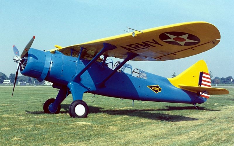
The Douglas O-46A was designed to operate from established airfields behind fairly static battle lines as in World War I. The O-46 was a development of the earlier Douglas O-43. The 24th airframe of the O-43A contract was completed as the XO-46 prototype, with a revised wing and an engine switch, from the O-43’s inline engine to a radial engine, the Pratt & Whitney R-1535-7.

First flying in 1935, the Air Corps ordered 90 O-46As in the same year. They were built between May 1936 and April 1937.

In 1939, a report was issued on the O-46A which stated that it was too slow and heavy to outrun and out-manoeuvre enemy fighter aircraft, too heavy to operate from small, wet, unprepared fields, and too large to conceal beneath trees. This report was a forecast of the future, for World War II with its rapidly changing battle lines proved the need for light, manoeuvrable observation aircraft which could operate from unimproved airstrips. Consequently, in 1942, the “O” (observation) designation was changed to “L” (liaison).

At least 11 O-46s saw overseas duty; two were destroyed in the Japanese raid on Clark Field in the Philippines on 8 December 1941. The Maryland Air National Guard operated O-46As off the coast of New Jersey for anti-submarine duty. The remainder were declared obsolete in late 1942 and after that were used primarily in training and utility roles.

A proposed variant with a Wright R-1670-3 engine received the designation O-48 but was not built.

On 27 November 1942, O-46A (s/n 35-179) was part of the 81st Air Base Squadron, when it landed downwind at Brooks Field, Harlingen, Texas, ran out of runway and overturned. Written off, it was abandoned in place. More than 20 years later it was discovered by the Antique Airplane Association with trees growing through its wings, and in 1967, it was rescued and hauled to Ottumwa, Iowa. Restoration turned out to be beyond the organization’s capability, and in September 1970, it was traded to the National Museum of the United States Air Force for a flyable Douglas C-47 Skytrain. The (then) Air Force Museum had it restored at Purdue University, and placed it on display in 1974, the sole survivor of the 91 O-46s built.

O-46A
Powerplant: 1 × Pratt & Whitney R-1535-7 Twin Wasp Junior, 725 hp (541 kW)
Propeller: 3-bladed metal propeller
Wingspan: 45 ft 9 in (13.94 m)
Wing area: 332 sq ft (30.8 m2)
Length: 34 ft 6.75 in (10.5347 m)
Height: 10 ft 8.5 in (3.264 m)
Empty weight: 4,776 lb (2,166 kg)
Gross weight: 6,639 lb (3,011 kg)
Maximum speed: 200 mph (320 km/h, 170 kn) at 4,000 ft (1,200 m)
Cruise speed: 171 mph (275 km/h, 149 kn)
Range: 435 mi (700 km, 378 nmi)
Service ceiling: 24,150 ft (7,360 m)
Rate of climb: 1,765 ft/min (8.97 m/s)
Wing loading: 20 lb/sq ft (98 kg/m2)
Power/mass: 1.087 hp/lb (1.787 kW/kg)
Guns: 2 × .30 cal (7.62 mm) Browning machine guns (one wing mounted and one flexible)
Crew: 2

Douglas XBLR-2 / XB-19

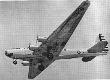
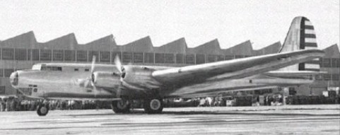
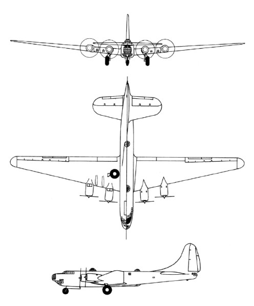
Originally designated XBLR-2 (eXperimental Bomber Long-Range 2), the XB-19 was essentially used as a test bed for very large bomber construction techniques and flight characteristics. The Douglas Aircraft Company had wanted to cancel the project because of the expense and extended construction time which made the aircraft obsolete before it ever flew. However, the Army Air Corps insisted the aircraft be completed for test use.
The XB-19’s first flight was 27 June 1941, more than 3 years after the construction contract was awarded. In 1943, the original radial engines were replaced by Allison V-3420 in-line engines and the aircraft was redesignated XB-19A. After testing was completed, the XB-19A was used as a cargo/transport aircraft until 1949 when it was scrapped.

Engines: 4 x 2000hp
Max take-off weight: 73467 kg/ 161968 lb
Wingspan: 64.62 m / 212 ft 0 in
Length: 40.23 m / 131 ft 12 in
Height: 13.03 m / 42 ft 9 in
Max. speed: 360 km/h / 224 mph
Ceiling: 7015 m / 23000 ft
Range: 8372 km / 5202 miles
Crew: 11
Armament: 2 x 37mm cannon, 5 x 12.7mm + 6 x 7.62mm machine-guns , 16330kg of bombs

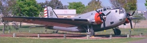
Douglas DB-1 / B-18 Bolo / DB-2 / Digby Mk I / C-58

With a 1934 US Army Air Corps requirement for a bomber with greater capability than their Martin B-10, Douglas drew on engineering experience of the DC-2 commercial transport.
Private-venture prototypes to meet the US Army’s requirements were evaluated at Wright Field, Ohio, in August 1935, these including the Boeing Model 299, Douglas DB-1 and Martin 146. The first was built as the B-17 Flying Fortress, the last was produced as an export variant of the Martin B-10/B-12 series, and the Douglas DB-1 (Douglas Bomber 1) was ordered in January 1936 into immediate production under the designation B-18.
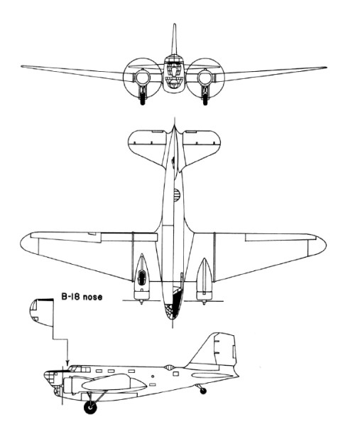
Derived from the commercial DC-2, the DB-1 prototype retained a basically similar wing, tail unit and powerplant. There were two differences in the wing: while retaining the same basic planform as the DC-2, the DB-1 had a 1.37m increase in span and was mounted in a mid-wing instead of low-wing position on an entirely new fuselage. The fuselage was deeper than that of the commercial transport to provide adequate accommodation for a crew of six, and to include nose and dorsal turrets, a bomb-aimer’s position, and an internal bomb bay. There was a third gunner’s position, with a ventral gun discharging via a tunnel in the underfuselage structure. Power was from two 694kW Wright R-1820-45 Cyclone 9 engines.
133 B-18s were covered by the first contract, including the single DB-1 which had served as a prototype. Production aircraft, which had the type name Bold, had equipment changes producing an increase in the normal loaded weight, and more-powerful Wright R-1820-45 radials. The last B-18 to come off the production line differed by having a power-operated nose turret, and carried the company identification DB-2, but this feature did not become standard on subsequent production aircraft.
A second contract covered 217 B-18A aircraft, placed in June 1937 (177) and mid-1938 (40). This version differed by having the bomb-aimer’s position extended forward and over the nose-gunner’s station, and the installation of more-powerful Wright R-1820-53 engines. Most of the USAAC’s bomber squadrons were equipped with B-18s or B-18As in 1940, and the majority of the 33 B-18As which equipped the USAAC’s 5th and 11th Bomb Groups, based on Hawaiian airfields, were destroyed when the Japanese launched their attack on Pearl Harbor.
When in 1942 B-18s were replaced in first-line service by B-17s, 122 B-18As were equipped with search radar and magnetic anomaly detection (MAD) equipment for deployment in the Caribbean on anti-submarine patrols under the designation B-18B. The Royal Canadian Air Force also acquired 20 B-18As which, under the designation Digby Mk I, were employed on maritime patrol. The designation B-18C applied to two other aircraft reconfigured for ASW patrol. Another two aircraft were converted for use in a transport role under the designation C-58, but many others were used similarly without conversion or redesignation.

B-18A
Engines: 2 x Wright R-1820-53 Cyclone 9, 746kW / 986 hp
Max take-off weight: 12552 kg / 27673 lb
Empty weight: 7403 kg / 16321 lb
Wingspan: 27.28 m / 89 ft 6 in
Length: 17.63 m / 57 ft 10 in
Height: 4.62 m / 15 ft 2 in
Wing area: 89.65 sq.m / 964.98 sq ft
Wing loading: 28.70 lb/sq.ft / 140.0 kg/sq.m
Max. speed: 187 kts / 346 km/h / 215 mph
Cruise speed: 145 kts / 269 km/h / 167 mph
Service ceiling: 7285 m / 23900 ft
Range: 1043 nm / 1937 km / 1204 miles
Armament: 3 x 7.62mm (0.30in) machine-guns, 2948kg of bombs
Crew: 6

Douglas XT3D

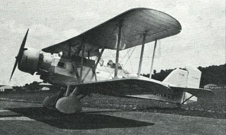
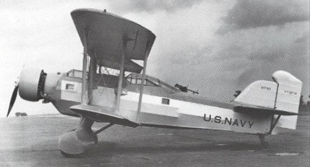
Designed and built to meet a US Navy requirement for a three-seat torpedo-bomber, the Douglas XT3D-1 prototype was first flown in early 1931. A biplane, basically of metal construction with fabric covering, the XT3D-1 incorporated folding wings and arrester gear for carrier-based operations, had fixed tailwheel landing gear, and was powered initially by a Pratt & Whitney S2B1-C Hornet radial piston engine. Accommodation was provided for a crew of three in open cockpits, a bomb-aimer/gunner forward, the pilot in the centre cockpit, just aft of the wing trailing edge, and a second gunner to his rear.
Failing to meet requirements in its initial service trials, the XT3D-1 was returned to Douglas for modification, gaining a more powerful 597kW Pratt & Whitney XR-1830-54 radial engine, wheel fairings for the main units and an enclosed canopy for the two rearmost cockpits. Redesignated XT3D-2, it was returned for further service testing but again failed to attract a production order. It was flown by the US Navy for about 10 years for general-purpose duties before being relegated for use as an instructional airframe in 1941.

Engine: 2 x Pratt & Whitney S2B1-G Hornet, 429kW
Max take-off weight: 3564 kg / 7857 lb
Empty weight: 1922 kg / 4237 lb
Wingspan: 15.24 m / 50 ft 0 in
Length: 10.79 m / 35 ft 5 in
Height: 4.03 m / 13 ft 3 in
Wing area: 57.97 sq.m / 623.98 sq ft
Max. speed: 206 km/h / 128 mph
Ceiling: 4265 m / 14000 ft
Range: 893 km / 555 miles
Armament: 2 x 7.62mm guns, 832kg of bombs

Douglas B-7 / O-35

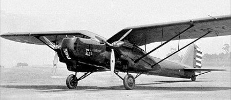
In the late 1920s the US War Department ordered two Fokker XO-27 prototypes. Fearing it might lose a valuable source of revenue, Douglas designed an aircraft incorporating all-metal cantilever monoplanes with retractable landing gear features and in March 1930 received an order for one example each of the Douglas XO-35 and Douglas XO-36. They were intended to differ only in their engines, the former having geared Curtiss Conquerors and the latter a direct-drive version of the same engine.
In the event, the XO-36 was redesignated XB-7 and built as a bomber. In a parallel development the second of the Fokker XO-27s was completed as the XB-8 bomber. Later, six YO-27s and six Y1O-27s were delivered to the US Army.

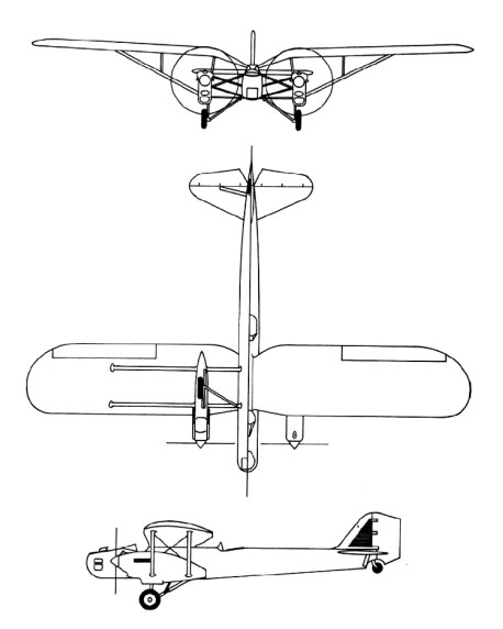
The Douglas XO-35 was test-flown in spring 1931. It was a monoplane with a gull wing set high on the fuselage, the main units of its landing gear retracting into streamlined engine nacelles leaving only the lower part of the wheels exposed. The engine nacelles were attached to the wing undersurfaces and fuselage sides by complex strut assemblies, and the fuselage having corrugated metal sheet covering. There were open gunners’ cockpits in the nose and amidships; the pilot’s open cockpit was located immediately forward of the wing leading edge; and the fourth crew member, the radio-operator, had an enclosed cabin behind the pilot’s position.
The XB-7 was almost identical, but had underfuselage racks for up to 544kg of bombs. During the US Fiscal Year 1932 orders were placed for seven Y1B-7 and five Y1O-35 service-test aircraft. These differed from the prototypes mainly by having smooth metal sheet covering for the fuselages, and strut- rather than wire-braced horizontal tailplanes.
The Y1B-7s, later designated B-7, were attached to the two US Army bombardment squadrons based at March Field, California, while the O-35 aircraft (previously Y1O-35s) flew with observation units. In February 1934 the five O-35s, six surviving B-7s and XO-35 prototype were all assigned to the air mail route linking Wyoming with the west coast of the United States. Operations at night and in bad weather took their toll and in the four-month emergency period during which the US Army ran the nation’s air mail service no fewer than four of the B-7s were lost in crashes. Soon afterwards the remaining B-7s and O-35s were relegated to second-line duties, an O-35 being the last to be grounded in February 1939.

B-7
Crew: 4
Engine: 2 x Curtiss V-1570-53 Conqueror, 503kW
Max take-off weight: 5070 kg / 11177 lb
Loaded weight: 2503 kg / 5518 lb
Wingspan: 19.81 m / 64 ft 12 in
Length: 14.0 m / 45 ft 11 in
Height: 3.53 m / 11 ft 7 in
Wing area: 57.71 sq.m / 621.18 sq ft
Max. Speed: 293 km/h / 182 mph
Cruise speed: 254 km/h / 158 mph
Ceiling: 6220 m / 20400 ft
Range: 660 km / 410 miles
Armament: 2 x 7.62mm machine-guns, 540kg of bombs

Douglas O-2 / BT

O-2M

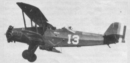
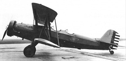
In 1926 as the principal combat element of Mexican Army Aviation, eight Douglas O 2C observation aircraft were procured from the USA these were to be supplemented by nine O 2Ms and three O¬2M 2s.
The excellent flight characteristics of the Douglas O-2 family led to the conversion of 40 O-2Ks in 1930 as basic trainers for the US Army. Dual controls were installed and armament was deleted, the modified aircraft then being designated Douglas BT-1. The only O-32 to be built was given dual controls, also in 1930, and became designated BT-2. Thirty O-32As were modified similarly to the O-2Ks; used by US Army and National Guard units for basic training these were redesignated BT-2A. Some 146 BT-2B aircraft were built as such, the first appearing in 1931. Powered by the 336kW Pratt & Whitney R-1340-11 radial, they survived many years in basic training units.

BT

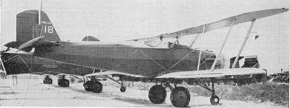
BT-2B was converted in 1940 to Type A-4 target aircraft by installation of radio equipment and conversion to nosewheel undercarriage.

Type A-4 target aircraft

Douglas BT-2B
Engine: 1 x Pratt & Whitney R-1340-11 radial, 336kW
Max take-off weight: 1845 kg / 4068 lb
Empty weight: 1324 kg / 2919 lb
Wingspan: 12.19 m / 39 ft 12 in
Length: 9.5 m / 31 ft 2 in
Height: 3.3 m / 10 ft 10 in
Wing area: 33.63 sq.m / 361.99 sq ft
Max. speed: 216 km/h / 134 mph
Cruise speed: 188 km/h / 117 mph
Ceiling: 5850 m / 19200 ft
Range: 515 km / 320 miles

O-2C
O-2M
O-2M-2