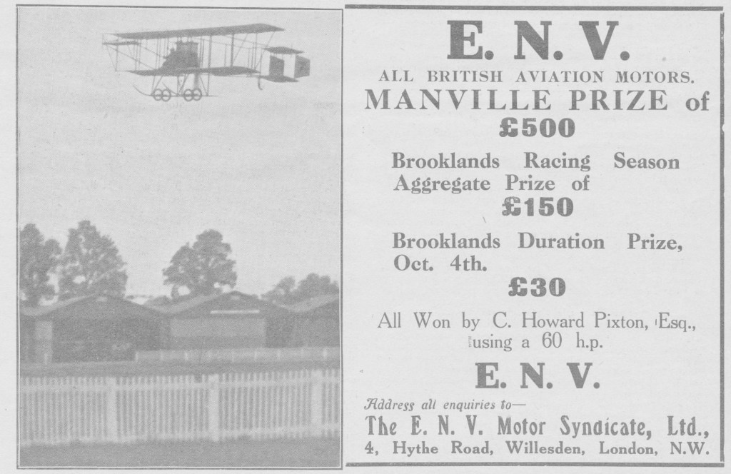
The three horizontally opposed, four-cylinder, overhead-valve engines that appeared at aircraft shows between October 1909-10 were E.N.V.’s only departure from their standard 90° V8 layout. Technical details are rather sparse, but the 1909 engine had steel cylinders and combined inlet/exhaust valves. The 30 hp 1910 engine had separate steel cylinder heads and barrels, screwed and brazed together. Inlet and exhaust valves were also separated, placed respectively below and above the cylinders and worked by push/pull rods and rockers. Only one of these horizontal engines flew, powering the Neale monoplane of 1909-10 at Brooklands for a short time.
25/30 hp Year: 1909 Power: 24 hp @ 1,200 rpm Capacity: 4,100cc Bore×Stroke: 109×110mm Weight: 30kg Manufactured in France
H Year: 1910 Power: 30 hp @ 1,200 rpm Capacity: 2,300cc Bore×Stroke: 90×90mm Weight: 40 kg bare
30 hp Year: 1910 Power: 30 hp Capacity: 3,050cc Bore×Stroke: 80×120mm Weight: 60kg
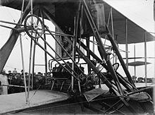
ENV engine installation in the Cody Mark IC Cathedral
E.N.V.’s V-8 engines appeared in six different models. Most of these were identified by a letter, though contemporary sources often refer to them by power. The assignment of the letters C, D, F and T is known from contemporary sources. The one type known to have pre-dated the C has been assigned the letter A by a later historian, a notation followed here. The last engine is usually known as the 1914 100 hp E.N.V.
The physical details of all the engines, such as bore and stroke etc. are known from both contemporary records and surviving examples. There were also variations within types, as development proceeded. Nonetheless, all the V-8s had much in common. They all had their cylinder banks separated by 90°, leaving space within the V for inlet manifolds and valvegear. All were water-cooled; each cylinder was enclosed with an electrolytically formed copper jacket. Initially these were produced with a variant of the lost wax process. The cylinders were coated with wax, which was then coated with black lead to make it electrically conductive and copper plated. Afterwards the wax was removed by heating. Later, the insulating wax was replaced with electrically conducting, low melting point white metal, simplifying the process. Pistons were made of steel, with cast iron rings, and the crankcases were cast aluminium. There was one plug per cylinder, supplied by a gear-driven magneto alone or with an additional battery-driven ignition coil and distributor for dual ignition.
The types A, C, D and F were all side-valve engines, with valves operated by push rods running exposed and parallel to the cylinder axes, driven within the V from a central, gear-driven camshaft above the crankshaft. All camshafts were hollow for lubrication. The cylinder cooling jackets surrounded the cylinders, then turned inward with flattened faces for inlet and exhaust manifolds and push rods. The exhaust stubs were vertical, each bank of cylinders feeding its own horizontal pipe. The inlet stubs entered the cylinder head at right angles. The earliest type A engines had a pair of inlet tubes, one for each bank and fed from a carburettor at the front.
Slightly later model As and types C and F placed the carburettor between the cylinder banks, halfway along the engine axis. Fuel and air was passed to a spherical copper mixing chamber above the carburettor, then via four radial copper tubes which finally branched into pairs the feed the inlet ports symmetrically. The smaller type D retained the end positioned carburettor. These engines all had cast iron cylinders. The types A and C were very similar in construction as well as capacity, but a major change in crankshaft design was introduced with the smaller type D and inherited by the F. The A and C types had a crankshaft supported by only three plain bearings and the width of the central one required a greater space between the second and third cylinder of each bank, visibly dividing each into blocks of two. The crankshafts of the D and F types had five ball race bearings, one between each cylinder and two end bearings; the output thrust bearing was a double race to allow for pusher or tractor configurations. The new bearing arrangement permitted an equal cylinder spacing. The type FA was a type F with an extended crankshaft, mounted in a very prominent, conical crankcase extension. The type T, discussed below, had a similar extension, which in that case at least allowed a larger diameter thrust bearing to be used.
Though heavy, the E.N.V. models A and C provided some of the earliest European fliers with a relatively powerful engine. Some Voisin biplanes used them between 1908 and 1910 and S.F. Cody fitted his first pusher biplane with a type C in the second half of 1909. His second aircraft also used that engine in the autumn of 1910. The types D and F had significantly better power-to-weight ratios than the first two models and become E.N.V.’s most popular products, being widely used in 1910 and 1911. After that they were eclipsed by the new, light rotary engines.
November 1911
The last two V8’s, the T and the 100 hp were not successful. Though tested, they never flew. The type T introduced steel cylinders and was an overhead-valve engine with vertically mounted valves operated from a central camshaft by thin pull rods and rockers. The carburettor was mounted centrally at the front, feeding a central tube which ran to the back of the engine, divided and ran back along each cylinder bank. Dual magneto/coil and battery ignition was provided. The 100 hp engine was also an overhead-valve engine in the sense that the port opened directly into the cylinder head, though the valves were mounted horizontally. This arrangement required an unusual shape of combustion chamber but enabled the valves to be operated directly from a central crankshaft raised on pillars to cylinder head height. Vibrations of this crankshaft and weakness of a new cylinder head restraint system dogged the engine, the last E.N.V. made.
A Type: 90° V-8 Year: 1908 Power: 50 hp @ 1,000 rpm Maximum Power: 60 hp Valve configuration: side Capacity: 8,171cc Bore×Stroke: 100×130mm Weight: 200kg Manufactured in France
C Type: 90° V-8 Year: 1908-9 Power: 65 hp @ 1,180 rpm Maximum Power: 90 hp for 15 min claimed Valve configuration: side Capacity: 8,171cc Bore×Stroke: 100×130mm Weight: 170kg Manufactured in France
D Type: 90° V-8 Year: 1909-10 Power: 30 hp @ 1,000 rpm Maximum Power: 40 hp @ 1,400 rpm Valve configuration: side Capacity: 4,087cc Bore×Stroke: 85×90mm Weight: 70kg Manufactured in France & UK
F Type: 90° V-8 Year: 1909-11 Power: 59 hp @ 1,000 rpm Maximum Power: 88 hp @ 1,500 rpm Valve configuration: side Capacity: 7,623cc Bore×Stroke: 105×110mm Weight: kg Manufactured in France & UK
FA Type: 90° V-8 Year: 1909-11 Power: 59 hp @ 1,000 rpm Maximum Power: 88 hp @ 1,500 rpm Valve configuration: side Capacity: 7,623cc Bore×Stroke: 105×110mm Weight: kg Manufactured in France
E.N.V. was an early manufacturer of aircraft engines, originally called the London and Parisian Motor Company their first model appearing in 1908. E.N.V. engines were used by several pioneer aircraft builders and were produced in both France and the UK until about 1914.
The London and Parisian Motor Co. was an Anglo-French venture registered in London in 1908 and largely backed with British capital and expertise. The castings and forgings for its engines were made in Sheffield where the company was originally based, then taken to France for assembly. The reason for this was that there was much more aeronautical activity in France than in England in 1908, but the French were taxing imported machinery. The French works were in Courbevoie in the Paris suburbs. By 1909 there was more aviation activity in England and E.N.V. decided to begin full manufacture at home, at Willesden, London. At that time a separate company was formed to produce the aero-engines in Willesden, The E.N.V. Motor Syndicate Ltd. E.N.V. was a contraction of French phrase “en-V” (“in a V”), which was a common name at the time for a V-engine. Most of their engines were 90° V-8s — the idea for the V8 engine itself originated with French engineer Leon Levavasseur in 1902. All of E.N.V.’s V8 engines were water-cooled inline engines. The first two models were powerful but heavy, while the later “D” and “F” types were lighter yet reliable, with power ratings of 37 hp (26 kW) and 74 hp (51 kW) respectively. These were widely used from 1909 in both Britain and France; in England well known pioneers like S.F. Cody, A.V. Roe, Claude Grahame-White, Moore-Brabazon and T.O.M. Sopwith used them.
In France, pioneers such as Henri Rougier, Pierre de Caters, Arthur Duray and Rene Metrot won prizes flying E.N.V. powered Voisin aircraft, and other French manufacturers like Farman and Antoinette used E.N.V.s in some of their machines. After about mid-1911, these water-cooled inline engines began to fall out of favour, superseded by the much lighter air-cooled radial engines from Anzani and in particular by the high-performing newcomer, the rotary engine, introduced by the Gnome et Rhône company. A good power-to-weight ratio was rather less critical for use in airship installations, and several used E.N.V. engines. The 100 hp (75 kW) V-8 submitted to the Naval and Military Aero Engine Contest of 1914 proved to have serious design flaws and as a result of its failure E.N.V withdrew from engine production.
E.N.V. Motors was incorporated on 30 May 1919 which then acquired on 3 June 1919 the engineering business of Joseph Frederick Laycock who traded under the name of E.N.V. Motor Company at Willesden. The property and assets were acquired for £45,000 and new company invested in new plant and machinery including building a new factory for manufacturing of gearboxes and camshafts for engines and in particular spiral bevel gears. In 1928 the company changed name to E.N.V. Engineering Company Limited.
The company continued successful production of bevel gears and camshafts for another 50 years; it produced individual components for several World War I aircraft and tank engines, and after the war built complete gearboxes for the automobile industry. In 1964 it became part of the Eaton, Yale and Towne group, losing its identity in 1968.
Production records have been lost, but probably 100-200 E.N.V. engines were made.
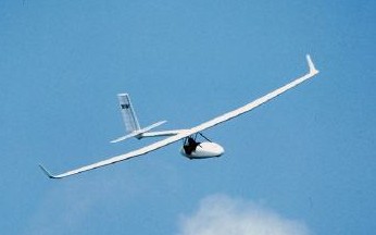
Designed at the Zurich University School of Engineering, the project started in 1998 with the concept prototype, stage P1, first flying in September 2001. The concept prototype, stage P2, modified from the P1, first flew in May 2002. Concept prototype, stage P2 E P2 with detail evolutions first flew in March 2003. The result was a successfully tested prototype Archaeopteryx P2E. For flight testing many successful flights were accomplished AND since then, by foot start and bungee cord, from the level by auto, winding, trike and UL-tows were achieved. The flight behaviour was of a completely new, safe airplane, which fulfils all requirements of its product requirement specifications and for the pilot new possibilities in the super-light sail flight opens.
Span: 13.6 m Length: 5.7 m Height: 2.9 m Wing area: 12.8 sq.m Wing loading: 9.0-12.5 kg/sq.m Take-off weight: 115-160 kg Pilot size: 1.65-1.95 m Pilot weight: 55-100 kg Load factor: +5.3/-2.65 g Stall: 30-35 km/h Vne: 130 km/h Min sink: 0.44-0.51 m/s Glide ratio: 28 Min turn radius 45 deg bank: 15 m
In 1959 the design teams of the German companies Bolkow, Heinkel and Messerschmitt were formed into a consortium named Entwicklungsring Sud to develop a Mach 2 VTOL interceptor for the Federal German defence ministry. Heinkel left the consortium in 1964 and in the following year it was re-formed as a company with the title Entwicklungsring Sud GmbH, EWR.
115 foreign companies’ participed including 35 in England, 60 in the US and 20 in France. A test rig built had three 2200 lb thrust Rolls-Royce engines installed in the same geometric arrangement as the VJ-101. Latter two 2759 lb thrust Rolls-Royce RB 145s in each of the two wing tip pods plus another two installed vertically in the fuselage were installed.
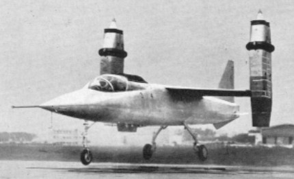
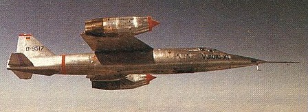
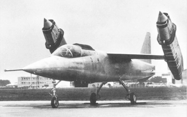
Two prototypes of the EWR VJ 101C single-seat experimental VTOL aircraft were built. Generally similar, they were both of high-wing monoplane configuration, primarily of light alloy construction, had retractable tricycle landing gear and accommodated the pilot in a pressurised cockpit, seated on a Martin-Baker ejection seat. Powerplant comprised six 2750-lb (1247-kg) thrust RB.145 turbojets, developed jointly by Rolls-Royce and MAN-Turbomotoren, with two mounted vertically in the fuselage, immediately aft of the cockpit, and two in a swivelling pod at each wingtip.
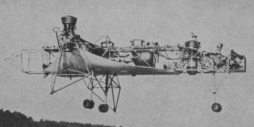
Those in the fuselage were used only for VTOL and low-speed flight, those in the wingtip pods for VTOL, low speed, transition from vertical to horizontal flight, and high-speed flight. Control of the aircraft in flight had been explored by a hovering rig powered by three Rolls-Royce RB.108 lift-jets, and by May 1963 this had made a total of 70 flights.
The VJ 101C X-1 prototype was flown for the first time in free hovering flight on 10 April 1963. It had exceeded a speed of Mach 1 several times before it crashed, following a vertical take-off, on 14 September 1964.
The VJ 101C X-2 differed by having afterburning engines in the wingtip pods, providing greater power (3550-lb / 1610-kg) for take-off and landing, and this made its first hovering flight on 12 June 1965. Four months later, on 22 October, the X-2 achieved the first full transitions from vertical to horizontal flight and vice versa, but development was discontinued soon after.
In absence of support by US Defence department or private manufacturers, the German government indicated in 1964 it won’t continue with a production version. Flight tests of the VJ.101C, including low supersonic advancement with afterburners fitted to the RB.145 engines, was continuing.
Production of a single-seat interceptor was planned, under the designation EWR VJ 101D, but this would have differed considerably from the research prototypes. VTOL lift would have been retained by a battery of Rolls-Royce/ MAN RB.162 lift-jets in the fuselage, but primary propulsion would have come from two Rolls-Royce/MAN RB.153 turbofans mounted in the rear fuselage, these relying upon thrust deflection for control purposes. None of these aircraft was built.
EWR VJ 101C X-1 Engines; 6 x Rolls-Royce/MAN RB.145, 1247kg / 2750-lb Max take-off weight; 6000 kg / 13228 lb Wingspan; 6.61 m / 21 ft 8 in Length; 15.70 m / 51 ft 6 in Height; 4.13 m / 13 ft 7 in Max. speed; 1.08M Crew; 1
Entwicklungsring Süd GmbH was formed of a Bölkow, Heinkel, and Messerschmitt design consortium on February 23,1959 at the suggestion of the Federal German Defense Ministry, to develop a Mach 2 VTOL intercepter. By May 1963 70 flights had been made with VJ 101C research aircraft, which had tilting jet-pods at wingtips. Studies were made for an entirely different VJ 101D fighter. Heinkel withdrew in late 1964, and in July 1965 EWR changed from a consortium into a limited company. There was later an unsuccessful partnership with Fairchild Hiller.
Germany Based at Wilhelmshaven. Built in 1922, in conjunction with Prof. Junkers, a small two-seater cantilever biplane which had corrugated sheet-metal covering. Development was intended, and in summer 1922 an English selling price of £222 was mentioned. By 1925 the firm had ceased to exist.
A 1985 hang glider. The Foil 160B tended to be difficult with yaw at stupid airspeeds.
The Enterprise Wings Foil 152C, Upside: A very light handling, predictable, fun and safe glider with a respectable glide angle for its era. Only downside: The keel was long, meaning an overflare could easily end up in a broken keel.
The Foil Combat is a 1991 hang glider for Advanced pilots.
Foil Combat
The Foil Combat 2 is stable, predictable and responds quickly. It climbs and glides well. Like most performance gliders of this age it’s heavy, has loose side wires ground handles poorly but flies great.It lands fine but needs a good flare.
Foil Combat 2
The Foil Racer first appeared in 1987. The Foil 150B Kevlar Race was a great glider especially in thermals but you had to look out to not stall a wing under certain circumstances, easy landing, not the best setup and heavy for the size.
Foil Racer
Foil 140 Wing area: 13 m² Aspect ratio: 6.5 Hang glider weight: 27 kg
Foil 150 Wing area: 13.9 m² Aspect ratio: 6.8 Hang glider weight: 28 kg
Foil 160 Wing area: 14.8 m² Aspect ratio: 7 Hang glider weight: 30 kg
Foil 170 Wing area: 15.8 m² Aspect ratio: 7 Hang glider weight: 32 kg
Foil Combat 152 Wing area: 14.1 m² Wing span: 10.13 m Aspect ratio: 7.3 Hang glider weight: 34 kg Minimum pilot weight: 60 kg Maximum pilot weight: 90 kg Minimum speed: 29 km/h Maximum speed: 80 km/h Max glide ratio (L/H): 10.27 Max glide ratio speed: 40 km/h Minimum sink rate: 0.98 m/s Packed length short: 3.85 m Number of battens: 35 Nose angle: 130°
Foil Combat 2 139 Wing area: 12.9 m² Wing span: 9.7 m Hang glider weight: 31 kg Minimum pilot weight: 50 kg Maximum pilot weight: 75 kg Packed length: 5.5 m Packed length short: 3.8 m Number of battens: 29 Nose angle: 127°
Foil Combat 2 152 Wing area: 14.1 m² Wing span: 10.1 m Hang glider weight: 34 kg Minimum pilot weight: 60 kg Maximum pilot weight: 95 kg Packed length: 5.6 m Packed length short: 3.8 m Number of battens: 33 Nose angle: 127°
Foil Racer Wing area: 13 m² Wing span: 9.14 m Aspect ratio: 6.5 Hang glider weight: 27 kg Nose angle: 130°
Foil Racer Wing area: 13.9 m² Wing span: 9.7 m Aspect ratio: 6.8 Hang glider weight: 28 kg Nose angle: 130°
Foil Racer Wing area: 14.8 m² Wing span: 10.1 m Hang glider weight: 30 kg Nose angle: 130°
Foil Racer Wing area: 15.8 m² Wing span: 10.5 m Hang glider weight: 32 kg Nose angle: 130°
First appearing in 1991, the Enterprise Wings Aero is for Advanced pilots.
An easy double surface glider. Just a step up from a single surface glider. Mellow and predictable handling. They have all different features depending on their age.
Aero 145 Wing area: 13.47 m² Wing span: 8.3 m Aspect ratio: 5.1 Hang glider weight: 27 kg Minimum pilot weight: 45 kg Maximum pilot weight: 75 kg Packed length: 5.2 m Packed length short: 3.9 m Number of battens: 19 Nose angle: 122°
Aero 165 Wing area: 15.3 m² Wing span: 9 m Aspect ratio: 5.3 Hang glider weight: 29 kg Minimum pilot weight: 60 kg Maximum pilot weight: 90 kg Packed length: 5.6 m Packed length short: 4.1 m Number of battens: 19 Nose angle: 122°