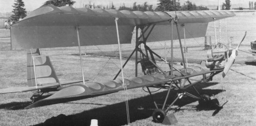
Hovey Delta Bird

Single seat single engined biplane with conventional three axis control. Wing has unswept leading and trailing edges, and constant chord; conventional tall. Pitch control by elevator on tail; yaw control by fin mounted rudder; roll control by full span ailerons on upper wing; control inputs through stick for pitch/roll and pedals for yaw. Wing braced by struts and transverse X cables; wing profile; double surface. Undercarriage has three wheels in tail dragger formation. Push right go right tailwheel steering connected to yaw control. Aluminium tube framework, without pod. Engine mounted between wings driving tractor propeller. Tubing from 6061T6 aluminium; galvanised steel rigging; Dacron wing covering.
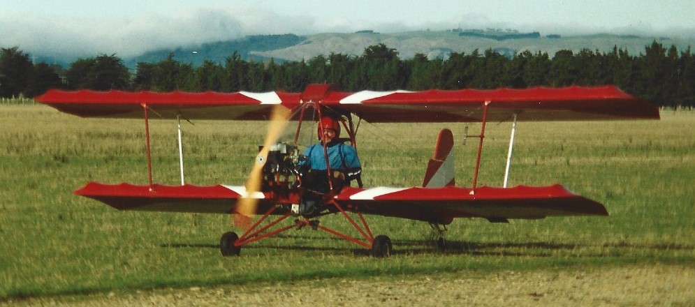
This three axis machine is a biplane which was revealed to the public at the EAA convention for amateur constructors, Oshkosh, in August 1982, where it was hailed as a modernised version of the Whing Ding II with a simpler structure and more power. The adoption of an aluminium tubular structure allowed Aircraft Specialties to offer the Delta Bird in plan form, as with the other two aircraft, but also as a kit requiring around 200 h for assembly. In place of the pusher common to the Beta Bird and the Whing Ding II, the motor is mounted as a tractor on a triangular framework at the front of the main framework. The exhaust pipe passes under this triangular section and finishes by the junction of the two triangular frameworks which support the main wheels, an arrangement designed to allow all terrain use. The machine retains conventional controls with ailerons on the trailing edges of the two top wings, a rudder hinging from the fin and the elevators from the horizontal stabiliser; they are all of generous proportions.
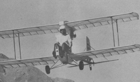
Engine: Cuyuna 430R, 30 hp at 5500 rpm.
Propeller diameter and pitch 54 x 27 inch, 1.37 x 0.69 m.
Belt reduction, ratio 2.0/1.
Power per unit area 0.20 hp/sq.ft, 2.1 hp/sq.m.
Fuel capacity 3.5 US gal, 2.9 Imp gal, 13.2 litre.
Length overall 15.0 ft, 4.57 m.
Height overall 6.0ft, 1.83m.
Wing span 24.0ft, 7.31m.
Constant chord 3.5 ft, 1.07 m.
Sweepback 0 deg.
Tailplane span 8.0 ft, 2.44 m.
Fin height 3.7 ft, 1.13 m.
Total wing area 152 sq.ft, 14.1 sq.m.
Fin area 9.0 sq.ft, 0.84sq.m .
Tailplane area 20.0 sq.ft, 1.86 sq.m.
Wing aspect ratio 6.9/1.
Wheel track 6.3ft, 1.92 m.
Main wheels diameter overall 15 inch, 39 cm.
Empty weight 218 lb, 99kg.
Max take off weight 450 lb, 204kg.
Payload 232 lb, 105 kg.
Max wing loading 2.96 lb/sq.ft, 14.5 kg/sq.m.
Max power loading 15.0 lb/hp, 6.8kg/hp.
Load factors +3.5, 3.5 design; +5.3, 5.3 ulti¬mate.
Max level speed 60mph, 97kph.
Never exceed speed 60mph, 97kph.
Max cruising speed 45mph, 72kph.
Stalling speed 26 mph, 42 kph.
Max climb rate at sea level 400 ft/min, 2.0 m/s.
Best glide ratio with power off 6/1.
Take off distance 250 ft, 75 m.
Landing distance 250 ft, 75 m.
Range at average cruising speed 50 mile, 80km.
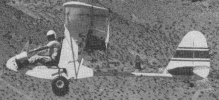
Hovey Beta Bird

The Beta Bird, designed in 1977 but not flown until April 1979 at Mojave, California, is a high wing monoplane version of the Whing Ding II, with which it shares a common fuselage. Like the biplane, the conventional tailplane is carried on a tubular boom and there is a tailwheel undercarriage. Wing profile Hovey BB 14. Brakes on main wheels. Engine mounted below wing. The Beta Bird was initially known as the Bushwacker.
Flight handling characteristics are very good, with an extremely docile stall. Rugged reliability was proven in off-airport operations in high desert country. Single-place, single-engine, strut-braced monoplane followup to Whing Ding II biplane, using drooperons. Stick-and-rudder 3-axis controls. Nose cowl and instrument panel included. Landing gear: Two mains with large 600×6 wheels & tires (from Cessna 150) for rough-field operation, using individually operated hydraulic toe brakes. Tail-wheel non-swiveling, steered with rudder cable linkage. Powerplant: Converted VW engine, pusher mounted, direct drive to 54×24 prop. It is powered by a 1,385-cc converted VW engine and offers the homebuilder simplified methods of construction. The wings fold for transport or storage. The fuselage pod is plywood and spruce construction with a stiffened aluminum tail boom to support the tail. The wings are spruce in a two-spar configuration, and the ribs are single-piece aluminum tubes. The tail group is fabricated from aluminum tubing, pop-riveted together with gussets and covered with Dacron. Only 250 feet are needed for takeoff and landing, and the 7 1/2-gallon fuel tank is good for 180 miles.

Engine: Volkswagen 1385cc, 45 hp.
Power per unit area 0.52 hp/sq.ft, 5.6 hp/sq.m.
Length overall 16.5 ft, 5.02 m.
Height overall 6.0ft, 1.83m.
Wing span 25.5ft, 7.77m.
Sweepback 0 deg.
Total wing area 87 sq.ft, 8.1 sq.m.
Wing aspect ratio. 7.3/1.
Empty weight 405 lb, 184kg.
Max take off weight 650 lb, 295kg.
Payload 245 lb, 111kg.
Max wing loading 7.47 lb/sq.ft, 36.4kg/sq.m.
Max power loading 14.4 lb/hp, 6.6kg/hp.
Max level speed 85 mph, 137 kph.
Never exceed speed 95 mph, 153kph.
Cruising speed 70mph, 113kph.
Stalling speed 40 mph, 64 kph.
Max climb rate at sea level 400ft/min, 2.0m/s.
Take off distance 250 ft, 75 m.
Range at average cruis¬ing speed 130 mile, 209 km.

Engine: VW 1800cc
hp Range: 50-85
Length: 16.5 ft
Wingspan: 26 ft
Wing area; 110 sq.ft
Empty weight; 405 lb
Gross weight: 650 lb
Fuel cap: 7.5 USG
Cruise: 80 mph
Stall: 45 mph
Rate of climb: 750 fpm
Takeoff dist: 250 ft
Landing dist: 150 ft
Seats: 1
Landing gear: tailwheel
LSA: yes

Horton Alita HX

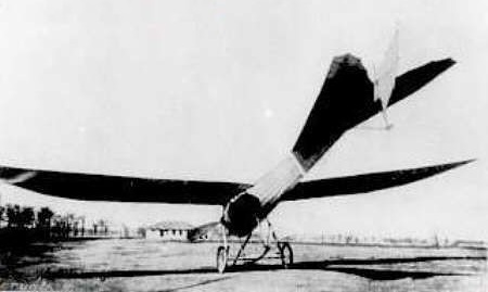
The first Alita designed by Reimar Horton was built by a group of enthusists in Argentina in 1953. It was destroyed in a storm.

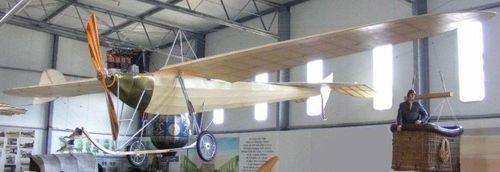
The version B was then built, which never flew, and is in the aeronautical museum of moron Buenos Aires, Argentina.

HXa
Wing area: 11.2 m²
Wing span: 7.54 m
Hang glider weight: 39 kg
Minimum pilot weight: 75 kg
Maximum pilot weight: 75 kg
Maximum speed: 150 km/h
Max glide ratio: 30
Max glide ratio speed: 50 km/h
Maximum speed: 170 km/h
Max glide ratio: 18
Max glide ratio speed: 78 km/h
Landing speed: 42 km/h

HXb
Wing area: 17.5 m²
Wing span: 10 m
Hang glider weight: 39 kg
Minimum pilot weight: 75 kg
Maximum pilot weight: 75 kg
Maximum speed: 150 km/h
Max glide ratio: 20
Max glide ratio speed: 60 km/h
Landing speed: 36 km/h

HXc
Wing span: 15 m
Hang glider weight: 42 kg
Minimum pilot weight: 90 kg
Maximum pilot weight: 90 kg
Maximum speed: 150 km/h
Max glide ratio: 30
Max glide ratio speed: 50 km/h
Landing speed: 39 km/h

Horton Bomber Project

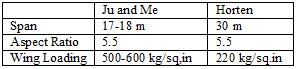
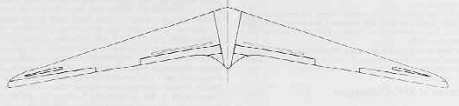
In February 1945 a committee under Professor Bock with representatives from Junkers, Messerschmitt and Horten, deliberated over the optimum design for a 4 jet engined bomber. Designs by Junkers (Ju 287. A swept forward tailed aircraft), Messerschmitt (Project 1107 as swept back tailed aircraft), and Horten (swept back tailless) were considered, and a joint report issued giving the committee’s opinion on the best estimate for relative performance. Junkers published the report.
The specification to be noted was for 900 kph at 10 km height and a range of 3,000 km using four H 11 jets. According to Horten the committee decided that his machine, given the same top speed as the others would have more range and less landing speed. (125 kph against the 175 kph for the others.) Alternatively he could carry 8 tons (metric) of bombs against the 4 by his competitors for the same range.
The dimensions of the aircraft were roughly as follows:

Horten said the agreed CDo for this aircraft was 0.0078 excluding Mach number correction.
In the structural design he reckoned to save 6% of the all up weight (spar and rib weight) compared with the conventional type. He thought the committee a bit unfair because they insisted on increasing his estimate of structure weight by about a ton.
All the above figures were remembered by Horton, who used them as a rough illustration. They are not accurate.

Horton Ho XIV

This was a sports sailplane designed to conform to the 1939 Olympic Games specification. It was designed for simplicity and ease of production. The first aircraft was built from sketches and proper drawings for the production type were made later with slight modifications. Construction was carried out at Hersfeld.
Span was 15 m and aspect ratio 16.2. The wing had 23 degree leading edge sweep and 8.6 degree total twist. Sections were 4% camber and 17% thickness at the root with 10% thick symmetrical tips. Empty weight was 120 kg giving a flying weight of 225 kg.
Controls consisted of one Frise nose elevon per side with rudders and dive brakes of H IV design. The glider trimmed at CL=1.0 with elevons neutral.
The pilot was put in a prone position as on the H IV and the undercarriage arrangement was also similar but for the replacement of the rear skid by a wheel.

Wing span: 16m
Wing area: 15.76sq.m
Empty Weight: 150kg
Payload: 80kg
Gross Weight: 230kg
Wing Load: 14.6kg/sq.m
Aspect ratio: 16.2
L/DMax: 30 70 kph
MinSink: 0.62 m/s 55 kph
Seats: 1