Pelzner Biplane hang glider

Pelzner was a builder of doppeldecker hangegleiter. In 1921 and 1922 he carried off many prizes. He built all his own craft and developed a simple structure that proved strong enough to carry him safely on flight after flight without serious mishap, yet light enough for him to control flight by bodily movements, changing the centre of gravity to trim the aircraft and overcome the upsetting effect of gusts or turbulence.
Pelzner’s gliders were astonishingly cheap despite financial trouble and inflation in Germany they cost him less than 20 marks to build. Derigged, they were small enough to be loaded onto a passenger train as traveller’s luggage at no extra charge; the parcel measured about 2.7m long, 1.3 m high, but only 50 cm thick.
The various Pelzner gliders differed a good deal in size and detail, although all were built roughly to the same basic scheme. The earlier models were built smaller and very light; 5.4 m span with total wing area of 14 sq.m. The weighed less than 10 kg. The later types spanned up to 7 m with areas of 16.5 sq.m, and weighed twice as much. Probably as Pelzner’s skill improved he was able to control bigger and more efficient gliders.
The framework was two tapered longerons, a shoulder width apart, running fore and aft with the lower wing main spars running cross wise and attached with bolts. At the rear these two main members were drawn together to support the tail unit, and from the tail to the upper end of the main wing struts two diagonal members ran. This basic framework was of oval or streamlined section timber, 2.5 cm by 4 cm in cross section where the loads were greatest, thinning down to 2 x 3 cm elsewhere. The upper and lower wings both had two spars, the front spars being 4 cm by 0.5 cm section, the rear spars 3.5 x 0.8 cm on the lower wing and 3.6 x 1.1 cm on the upper. Light curved ribs were bound to the spars, and the two wings were joined by light vertical struts, the outer ones being spindled I section to save weight. The whole structure was braced with wire.
Pelzner covered his surfaces with oiled paper, glued onto the underside of the ribs of wing and tail. The leading edge of the lower wing was formed by the front spar, but the upper wing apparently had a light front member of wood or wire which gave a stiff entry to the primitive aerofoil. Some models had double thickness paper covering around the leading edge. The earliest models had no movable control surfaces at all, but later Pelzner fitted a rudder which he controlled by means of a sling around his right hand – a forward movement for a left turn, a backwards push for a right turn.
To manage these craft Pelzner worked out an athletic style of flying. At the 1921 meeting he accumulated a total flying time of 38 minutes, higher than any other pilot. He did this in a total of 62 flights aeraging over a half a minute each, some of them covering 400 and 500 m at his best glide ratio of about 6 to 1. In cash prizes he paid for his gliders hundreds of times over.
After monoplane glider flights the future was clearly not biplanes. Pelzner played little in the subsequent development of gliding.

Renard R.35

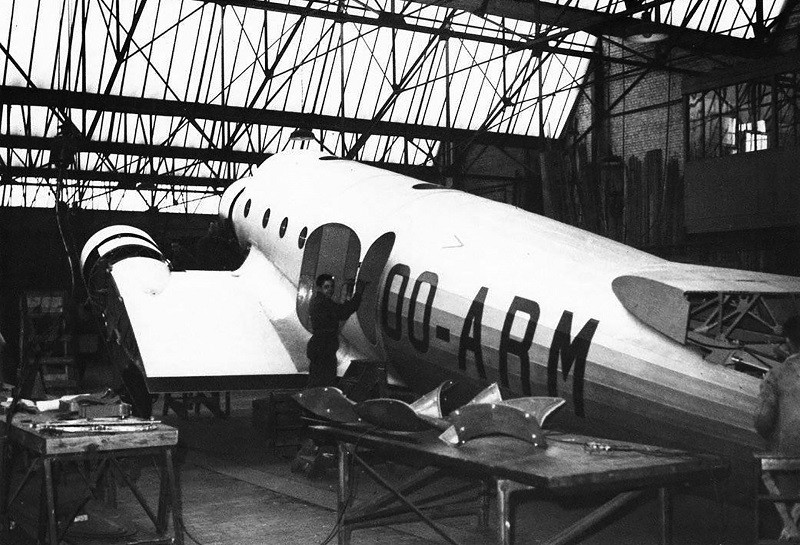
In the late 1930s, Belgian aircraft maker Constructions Aéronautiques G. Renard developed the R.35, a sleek, pressurised airliner built for long-distance travel. Designed to serve SABENA’s route to the Belgian Congo, the R.35 featured a low-wing monoplane layout with three engines and retractable landing gear.

Alfred Renard initiated the design in 1935. SABENA requested a three-engine configuration, prompting a metal monoplane that could seat 20 passengers in a pressurised cabin. On April 3, 1936, an order for a single prototype was confirmed. Though compatible with more powerful engines, the prototype used less powerful Gnome-Rhône 9Ks.

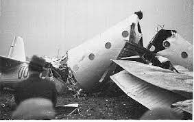
By early 1938, the R.35 was ready for testing. On April 1, it stood on Evere airfield, poised for high-speed taxi trials before a crowd of VIPs and journalists. After one ground run, it unexpectedly lifted off during the second. The pilot, Georges Van Damme, tried to complete a circuit, but the aircraft dove suddenly and crashed, killing Van Damme.

With the cause undetermined, SABENA withdrew its support, and the R.35 project was abandoned.

Gallery

Powerplant: 3 × Gnome-Rhône 9K, 560 kW (750 hp) each
Wingspan: 25.50 m (83 ft 8 in)
Length: 17.50 m (57 ft 5 in)
Wing area: 87 m2 (940 sq ft)
Height: 5.50 m (18 ft 1 in)
Empty weight: 6,100 kg (13,448 lb)
Max takeoff weight: 10,500 kg (23,149 lb)
Capacity: 20 passengers or 2,000 kg (4,400 lb)
Crew: 3 (2 pilots and radio operator)
Maximum speed: 435 km/h (270 mph, 235 kn) at 5,000 ft (1,500 m)
Cruise speed: 350 km/h (220 mph, 190 kn)
Range: 1,800 km (1,100 mi, 970 nmi)
Service ceiling: 9,000 m (30,000 ft)

Aerial Transport Corp V.B.L.-1

The 1921 V.B.L.-1, built by Aerial Transport Corp, was an open cockpit biplane described as an “express transport of three-ply construction.” 1922 Eaton Chronicles reported that Rogers Construction Co “… takes over the building of a Sport Biplane designed by C H Day of the defunct Aerial Transportation [sic] Corp.” Then in 1925, “Charles ‘Pop’ Dickinson buys the C D Air Express from Rogers,” which is described as a C H Day design. This would be conclusive proof that VBL-1 and CD Express are one and the same.

Berliner-Joyce XF3J-1

Designed by the US Navy Bureau of Aeronautics, the XF3J-1 was turned over to the Berliner-Joyce Corporation for development and construction. Ordered on 30 June 1932, this experimental single-seat shipboard fighter was completed in January 1934.
Of all-metal construction with a semi-monocoque fuselage and fabric-covered wings, the XF3J-1 was powered by a 625hp Wright XR-1510-26 radial. Armament was two 7.62mm synchronised machine guns, and provision was made for two 50kg bombs beneath the wings.
Although offering a good performance, the XF3J-1 was surpassed by the Grumman XF2F-1, and no further development was undertaken.

Engine: 625hp Wright XR-1510-26 radial
Empty weight: 1233 kg/2718 lb
Wingspan: 8.84 m/29 ft 0 in
Length: 6.98 m/23 ft 11 in
Height: 3.28 m/11 ft 9 in
Wing area: 22.26 sq.m/239.60 sq ft
Max. speed: 336 km/h/209 mph
Range: 1157 km/719 miles
Armament: two 7.62mm synchronised machine guns, two 50kg bombs

UFO 11

Aerobat glider

Built in 1930 in Oklahoma City, the Aerobat glider was made entirely of aircraft steel dural and hib-lum covered with flightex fabric. It had an adjustable seat to provide balance for and weight pilot.

In its trial flight this primary glider gained over 300 feet altitude with 4 minutes 30 seconds duration, taking off at 12 mph by auto-tow.

The glider was priced at $395 and pontoon equipment was optional at $100 extra.

Wingspan: 42 ft
Wing chord: 5 ft 6 in
Length: 16 ft 6 in
Glide ratio: 16-1
Landing speed: 15 mph

Bentley

By 1931, during the Great Depression, Bentley was having financial difficulties. When funds ran out in 1931, the receivers were negotiating with D.Napier & Sons Ltd for the sale of the remains of Bentley. However, Rolls-Royce put in a secret bid through a Liechtenstein company, and secured Bentley Motors for £125,256. For this, Rolls-Royce got the factory equipment, a number of incomplete car chassis, and the services of Walter Bentley for three years.

Zündapp 9-092 / Z 92

The Zündapp 9–092 or Z 92 was a German four-cylinder, air-cooled, inline aero engine made by Zündapp and used in light aircraft of the late-1930s.

The engine was developed from the smaller Zündapp 9-090. This inverted engine featured dual gear-driven camshafts with the valve rocker cover acting as the oil tank. It featured a single Bosch magneto ignition system. A total of approximately 200 engines were produced.

Applications:
Brunswick LF-1 Zaunkönig
Bücker Bü 180
Fieseler Fi 253
Gotha Go 150
Klemm Kl 105
Siebel Si 202

Specifications:
Type: Four-cylinder air-cooled inverted inline piston aircraft engine
Bore: 85 mm (3.35 in)
Stroke: 88 mm (3.46 in)
Displacement: 2 L (122 cu in)
Length: 800 mm
Width: 350 mm
Dry weight: 60 kg (132 lb
Valvetrain: Overhead valve
Fuel system: Downdraught carburettor
Cooling system: Air-cooled
Power output: 37 kw (50 hp) at 2,300 rpm
Compression ratio: 6.2:1
Power-to-weight ratio: 0.62 kW/kg (0.38 hp/lb)

Zmaj Fizir FP-1 / Fizir FP-2

In 1933, the command of the Yugoslav Royal Air Force (YRAF) decided to replace outdated planes with modern school aircraft, for transitional training from basic training to combat.

The designers, R. Fizir and D. Stankov, opted for a biplane concept, although the YRAF preferred a low wing (due to the development of modern combat aircraft). The Zmaj Factory designed a prototype Fizir FP-1, in 1993, but it did not satisfy all the requirements set by the YRAF. As a result, Rudolf Fizir and Dusan Stankov, made adjustments to the Fizir FP-1 and so the plane became the Fizir FP-2. In the end, the concept accepted.

A prototype Fizir FP-2 (Fizir Prelazni) with a Gnome-Rhone K-7 engine of 308 kW power was completed and test flown at the end of 1933. More test flights followed, and by 1934 the plane showed good results.

The Zmaj modified the FP-2 during 1934 using a Walter Pollux 2 engine of 235 kW power, but the results were not satisfactory.

Engine: 1 × Gnome-Rhone K7, 313 kW (420 hp)
Propeller: 2-blade
Wingspan: 10.80 m (35 ft 5 in)
Wing area: 28.80 sq.m (310.0 sq ft)
Length: 7.90 m (25 ft 11 in)
Height: 2.90 m (9 ft 6 in)
Empty weight: 740 kg (1,631 lb)
Gross weight: 1,450 kg (3,197 lb)
Maximum speed: 200 km/h (120 mph; 110 kn) 238 km/h at sea level
Range: 580 km (360 mi; 313 nmi)
Service ceiling: 6,800 m (22,310 ft)
Crew: 2