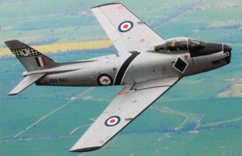
As early as 1949 the RAAF began planning a replacement jet fighter for the locally-built CAC Mustang and DHA Vampire. Gloster Meteors were obtained in 1951 for service with No 77 Squadron in the Korean War. In May of 1951, plans were finalised for CAC to build a locally-redesigned version of the North American F-86F Sabre swept-wing fighter. Due in part to the technical investigations initiated by CAC Manager, L. J. Wackett, the RAAF decided to install the 7,500 lb thrust Rolls-Royce Avon RA.7 turbojet in place of the 6,100 lb thrust General Electric J-47 engine. Major modifications included a larger nose-intake, positioning the Avon further aft than the J-47, and moving the engine servicing break-point. Other improvements called for increased fuel capacity, a revised cockpit layout, and replacement of the six 0.50″ machine guns with two 30mm Aden cannons. Consequently, CAC had to redesign 60 per cent of the airframe. The resultant aircraft was sometimes called the Avon-Sabre. The prototype CAC CA-26 Sabre Mk 30 first flew on 3 August 1953, with an imported Avon engine, piloted by Flight Lieutenant W. Scott. As A94-101 it went to Aircraft Research and Development Unit (ARDU) in 1955 and in latter years resided at Wagga as an instructional airframe; in 1960 it was used for ejection seat trials following three fatal Sabre accidents. The first production CA-27 Sabre, A94-901, flew on 13 July 1954 and was followed by 21 Mk 30s, A94-902/922, with imported Avons, and leading-edge slats. From 1955, the next 20 Sabre Mk 31s, A94-923/942, were powered with the CAC Avon Mk 20, had an extended leading-edge, additional fuel cells, and fitments for drop-tanks, bombs, and rockets. The earlier Mk 30s were then modified to Mk 31 standard. The final version of the CAC Sabre was the Mk 32 of which 69 were built, A94-943/990 and A94-351/371. They carried additional drop-tanks and rockets and, as from 1960, Sidewinder air-to-air missiles. All earlier Sabres were similarly modified, and retrospectively fitted with the CAC Avon Mk 26 engine which was first installed in A94-973. The last CAC Sabre, A94-371, completed acceptance trials on 19 December 1961. The first production Sabre, A94-901, went to ARDU on 19 August 1954. A Sabre Trials Flight was established at No 2 (Fighter) Operational Training Unit, RAAF Williamtown, on 1 November 1954 and No 75 Squadron became the first Sabre squadron after it reformed on 4 April 1955. No 3 Squadron received its first Sabres on 1 March 1956 and No 77 Squadron on 19 November 1956. In October 1958, No 3 Squadron deployed to RAAF Butterworth and was followed by No 77 Squadron in February 1959. As No 78 (Fighter) Wing, both squadrons used their Sabres against the Communist guerillas until 31 July 1960. No 76 Squadron reformed in January 1960 and joined No 2 (Fighter) Operational Conversion Unit and No 75 Squadron as the Sabre equipped No 81 Wing, RAAF Williamtown. On 1 June 1962, eight Sabres deployed from Butterworth to Ubon, Thailand, to counter communist activity. This detachment became No 79 Squadron until it withdrew and disbanded in August 1968. From 1964-5, the Mirage III began to replace the Sabre and, on 31 July 1971, the RAAF officially retired the Sabre from service.
CAC Sabre CA-27 Mk 32 Engine: One CAC RA.7 Avon Mk.26 turbojet, 3402 kg (7500 lb) Wingspan: 11.30 m (37 ft 1 in) Wing Area: 302.3sq.ft. / 28.1 sq.m Length 11.43 m (37 ft 6 in) Height 4.37 m (14 ft 4 in). Empty weight: 5443 kg (12 000 lb) Loaded weight: 8038 kg (17 720 lb) Maximum Takeoff weight: 21,210 lbs 9,621 kg Max speed 1126 km/h (608 kt, 700 mph) SL Cruise speed 885 km/h (478 kt, 550 mph) Range 1850 km (1000 nm) Service ceiling 52,000 ft (15,850 m) Rate of climb: 12,000 fpm at SL Armament: 2 x 30 mm Aden cannon 162 rounds per gun External load can include two AIM-9B Sidewinder missiles, up to 24 ground rockets, two 500 or 1,000lb bombs or eight practice bombs. Total internal fuel: 412 imp gal (1,873 litres) in two fuselage tanks, two outer wing panel tanks and tanks in the leading edges.
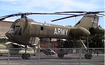
A US Army Heavy Lift Helicopter specification was approved in May 1971 for a 22 tonnes payload class helicopter. The Boeing XCH-62 / HLH proposal was selected over the Sikorsky S-73 (not built) and the only XCH-62 built (Serial number 73-22012) was put into storage at the US Army Aviation Museum at Fort Rucker Alabama prior to completion when the program was cancelled in October 1974. In 1983, NASA and DARPA (Defence Advanced Research Projects Agency) plans were initiated to resume the test programme but was cancelled again. The Boeing HLH was intentionally destroyed in 2005. According to an aviation museum exec, the HLH was simply a non-flying incomplete proof-of-concept mockup. Since it never achieved flight under its own power, it was not considered as an exhibit.
Engines: 3 x Allison T701 turboshaft, 5945kW Rotor diameter: 28.0m Length: 28 m Height: 11 m Max take-off weight: 53572kg Empty weight: 26754kg
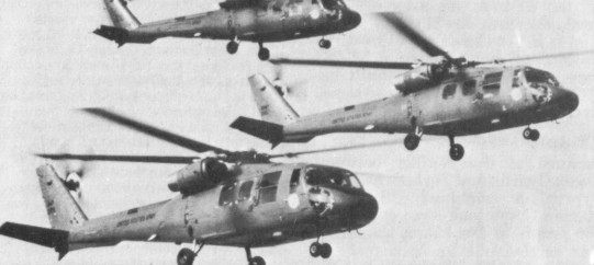
In 1971 the US Department of Defense issued a requirement for a new UTTAS (Utility Tactical Transport Aircraft System) helicopter to replace the Bell UH-1 in service with the US Army. The specification called for an aircraft capable of lifting an entire eleven-man infantry squad, or an equivalent weight in cargo, to medium altitudes at a minimum cruising speed of 323kph, and at considerably higher ambient temperatures. All designs proposed in response to the specification were required to use two General Electric T700-GE-700 turboshaft engines, and were to have wheeled landing gear, duplicate or heavily armored critical mechanical components, manual rotor blade folding, and only minimal avionics. In August 1972 the two leading contenders for UTTAS hardware were Sikorsky, with its S-70 ordered for evaluation as the YUH-60A, and Boeing Vertol, with the Boeing Vertol Model 179 (YUH-61A).
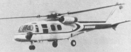
Boeing Vertol 179
The Model 179 was the first Boeing Vertol design with a single main rotor, designed round a similar type of hingeless semi-rigid main rotor of composite construction from the company’s licence-produced MBB BO.105. Powerplant was a pair of the specified General Electric YT700 turboshafts, located in two pods on the sides of the fuselage beside the transmission unit, above the rear of the cabin. The cabin could accommodate 11 troops (in addition to the three crew), or its area of 8.3sq.m could accommodate freight. Alternatively, a slung load of 3175kg could be lifted. The fuselage was of frame-and-stringer construction, with glassfibre and honeycomb being used for strength and to reduce maintenance. The conventional pod-and-boom fuselage had a four-blade glassfibre tail rotor and a large tail-plane with incidence varied automatically with airspeed for improved control. The landing gear was fixed tricycle, with single main wheels and a twin-wheel nose unit. Three model number 237 military prototypes were completed (serials 73-21656 through -21658), the first (73-21656) flying on 29 November 1974.
A competitive evaluation of the YUH-60A and YUH-61A was conducted from 1975, and the Sikorsky entrant was judged the winner in December 1976. All three YUH-61A prototypes were returned to Boeing-Vertol shortly after. Of the three prototypes built, one was modified for the LAMPS III programme as a ‘navalized’ version of the Model 237 in the Navy’s LAMPS II competition for a ship-based multi-purpose helicopter, but again lost out to the Sikorsky H-60. It had a four-blade rotor of composite material. Boeing Vertol completed a fourth prototype as the Model 179 civil demonstrator, with accommodation for between 14 and 20 passengers. A 14/20 passenger civil transport (N179BV), it failed to gain commercial interest. Failure to win the Army contract made its production uneconomic, and as a result only the prototype was built. Development of both types was later abandoned. YUH 61A prototypes 73-21656 & 58 were on display at Army Aviation Museum, Ft. Rucker, AL.
Boeing-Vertol Model 179 Engine: 2 x General Electric YT700-GE-700 turboshaft, 1146kW ain rotor diameter: 14.93m Length with rotors turning: 18.13m Height: 4.63m Max take-off weight: 8481kg Empty weight: 4302kg Max speed: 290km/h Cruising speed: 216km/h Hovering ceiling: 1722m Range: 964km
The Model 520 (military designation Boeing T60) was a family of small turboshaft / turboprop engines produced by Boeing, based on Boeing’s earlier Model 500 gas generator and Model 502 turboshaft engines.
Variants:
YT60-BO-2A Military turboshaft verion for testing.
520-2 (YT60-BO-2A) Free power turbine turboshaft rated at 475 hp (354.21 kW)
520-4 Turboprop rated at 475 hp (354.21 kW)
520-6 Direct drive turboshaft rated at 550 hp (410.13 kW) military power
520-8 Turboprop rated at 550 hp (410.13 kW)
Specifications:
520-6 Type: Turboshaft Length: 54.1 in (1,374 mm) Diameter: 25.14 in (639 mm) maximum height Dry weight: 250 lb (113 kg) Compressor: Single-stage centrifugal flow Combustors: 2 reverse flow can combustors Turbine: 1x radial gas generator power turbine stage Fuel type: Aviation kerosene Oil system: pressure spray/splash, oil specification: MIL-L-7808 Maximum power output: 550 hp (410.13 kW) military rating at 6,000 output shaft rpm Overall pressure ratio: 6:1 Turbine inlet temperature: Jet pipe Temperature: 1,025 °F (552 °C) Specific fuel consumption: 0.67 lb/hp-hr (0.41 kg/kW-hr) Power-to-weight ratio: 2.2 hp/lb (3.616 kW/kg)
The Boeing T50 (company designation Model 502) was a small turboshaft engine produced by Boeing. Based on Boeing’s earlier Model 500 gas generator, the T50’s main application was in the QH-50 DASH helicopter drone of the 1950s. An up-rated version designated Model 550 was developed to power the QH-50D and was given the military designation T50-BO-12.
Variants: T50-BO-4 270 hp (201.34 kW) at 6,000 output rpm, military rating turboprop. T50-BO-6 T50-BO-8 300 hp (223.71 kW) at 5,950 output rpm, revised reduction gear ratio, fuel system and other changes. T50-BO-8A T50-BO-10 330 hp (246.08 kW) at 6,000 output rpm T50-BO-12 502-10C 502-10V (T50-BO-4) 502-10VB 325 hp (242.35 kW) at 3,000 output rpm, variant of -10V / T50-B0-4 with revised reduction gear ratio. 502-10VC (T50-BO-8) 502-11 502-12B 502-W 502-14 (T50-BO-10) 550-1 (T50-BO-12) Applications T50 (Model 502) Gyrodyne QH-50 DASH Kaman K-225 Kaman HTK-1 Kaman K-1125 XL-19B Bird Dog Radioplane RP-77D
GT502 Stridsvagn 103
Specifications:
T50-BO-10 / 502-14 Type: Turboshaft Length: 37.2 in (945 mm) Diameter: 22.5 in (572 mm) Dry weight: 215 lb (98 kg) Compressor: Single-stage centrifugal flow Combustors: 2 can combustors Turbine: 1x axial gas generator power turbine stage + 1x axial free-power turbine stage Fuel type: Aviation kerosene Oil system: pressure spray/splash, oil specification: MIL-L-7808 Maximum power output: 330 hp (246.08 kW) military rating at 6,000 output shaft rpm Overall pressure ratio: 4.35:1 Turbine inlet temperature: Jet pipe Temperature: 1,140 °F (616 °C) Specific fuel consumption: 0.87 lb/hp-hr (0.532 kg/kW-hr) Power-to-weight ratio: 1.535 hp/lb (2.523 kW/kg)
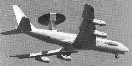
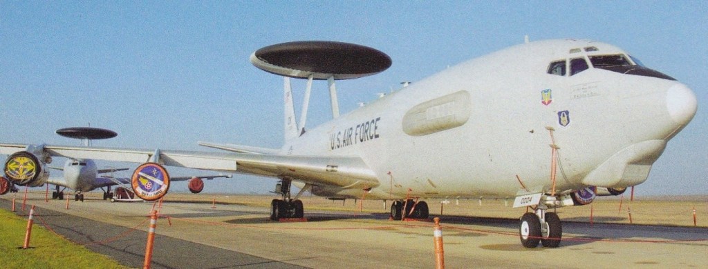
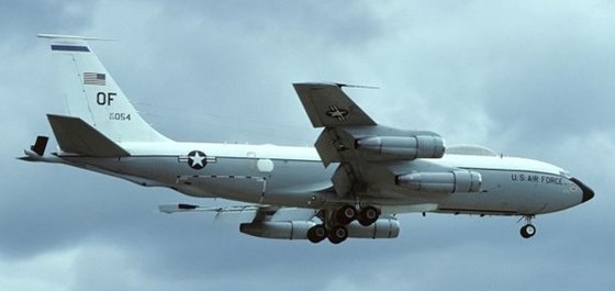
The requirement for an Airborne Warning And Control System (AWACS) aircraft was outlined by the US Air Force in 1963, at which time it was envisaged that a force of up to 64 of these specially-equipped aircraft would be needed. Economic considerations have made it necessary to reduce considerably the number of aircraft to be acquired initially. The resulting Boeing E-3A Sentry is essentially a flexible, jamming-resistant, mobile and survivable radar station, plus a command, communications and control centre, all contained within the airframe of a Boeing 707. In addition to its long-range high- or low-level surveillance capability, an AWACS aircraft can provide all-weather identification and tracking over all kinds of terrain, and the 22nd and subsequent aircraft also have a maritime surveillance capability. Boeing was the successful one of two contenders for the supply of an AWACS aircraft, being awarded a contract on 23 July 1970 to provide two prototypes under the designation EC-137D. The company’s proposed AWACS was based on the airframe of the Boeing Model 707-320B commercial transport, and the prototypes were modified in the first place to carry out comparative trials between the prototype downward-looking surveillance radars designed by the Hughes Aircraft company and Westinghouse Electric Corporation. These tests continued into the autumn of 1972, and on 5 October the USAF announced that Westinghouse had been selected as prime contractor for the advanced radar that was to be the essential core of the AWACS. This has the task of seeking and identifying low-flying targets at ranges as great as 370km, and in the case of high-altitude attack at even greater ranges.
Very little modification of the basic 707-320B airframe was needed to make it suitable for the new role. An external, large rotodome assembly carried on two wide-chord streamlined struts are secured to the upper rear fuselage. The remainder of the essential avionics antennae are housed within the wings, fuselage, fin and tailplane. New engine pylon fairings are provided for the more powerful turbofan engines of the pre-production EC-137Ds, and of the production aircraft which were designated E-3A and given the name Sentry. Internal modifications included strengthening of the cabin floor, provision of MPC (multi-purpose console) and other equipment bays, and addition of a crew rest area. Basic operations require a flight crew of four plus 13 AWACS specialist officers, but this number can vary for defence and tactical missions, and other personnel can be carried for systems management and radar maintenance.
Liquid cooling protects the radar transmitter, housed in the aft cargo hold, and a conventional air-cycle and ram-air environmental control system provides for crew comfort and the safe operation of other avionics equipment. Electrical power is supplied by generators with a combined output of 600 kVA. The over-fuselage rotodome is 9.14m in diameter and has a maximum depth of 1.83m. This incorporates the AN/APY-1 surveillance radar and IFF/TADIL C antennae. During operational use the rotodome is driven hydraulically at 6 rpm, but in non-operational flight is rotated at one twenty-fourth of this speed to ensure that low temperatures do not cause the bearing lubricant to congeal and prevent normal operation when required.
The Westinghouse radar, installed first in the 22nd Sentry, and scheduled to be updated in earlier aircraft, can function as a pulse and/or pulse-Doppler radar, and is operable in six different modes. The data processing capability of the first 23 E-3As is provided by an IBM 4 Pi CC-1 high-speed computer. It has a processing speed of some 740,000 operations per second, main memory capacity of 114,688 words, and a mass memory of 802,816 words. The IBM CC-2 computer, introduced on the 24th production aircraft, has a main memory capacity of 665,360 words. Also introduced on this aircraft is the newly-developed Joint Tactical Information Distribution System (JTIDS). This provides a high-speed secure communications channel for up to 98,000 users, and one that is less vulnerable to jamming.
The first Boeing E 3A Sentry aircraft was delivered to USAF Tactical Air Command’s 552nd Airborne Warning and Control Wing at Tinker AFB, Oklahoma, in March 1977, while the Nato fleet was delivered between January 1982 and April 1985. Saudi Arabian E3 Peace Sentinel AWACS and KE-3A tankers are powered by CFM-56 turbofans, and were delivered from late August 1986. The US/Nato Standard E-3A features a radar modified to track ships, a faster central computer with expanded memory, and improved communications equipment, including JT1DS. Ten USAF Standard E-3As are being upgraded to E-3C configuration by the addition of five more consoles and extra communications systems. The conversion of 24 early production USAF Core E-3As to E-3B standard covers the upgrade of communications equipment, including the installation of JTIDS and the fitting of extra consoles and a US/Nato Standard computer. Hardpoints for chaff/flare dispensers are also being fitted. The first E-3B conversion was delivered in July 1984. A force of 18 generally similar aircraft was acquired by NATO. Initial deliveries of NATO’s operational E-3As, which are based at Geilenkirchen, West Germany, were made during 1982. They differ from their USAF counterparts by comparatively minor changes in installed avionics to meet NATO communications requirements. They also introduced underwing hardpoints to carry self-defence weapons, but these mountings can be used optionally to carry ECM pods. The Sentry has also been sold to France and the United Kingdom, all export aircraft being powered by CFM56 high bypass ratio turbofans.
Flying for the first time on 27 June 1990 after leaving the Renton assembly line in April, was the first E-3F Sentry AWAC for the Armee de l’Air.
E-3A Sentry Engine : Pratt&Whitney TF33-PW-100 / 100A, 21,000 lb (9525 kgp) Length : 152 ft 11 in / 46.61 m Height : 42.421 ft / 12.93 m Wingspan : 145 ft 9 in / 44.42 m Wing area : 3050.518 sq.ft / 283.4 sq.m Max take off weight : 325061.1 lb / 147420.0 kg Weight empty : 170027.6 lb / 77110.0 kg Max. speed : 545 kt / 1010 km/h Cruising speed : 478 kt / 886 km/h Ceiling: 8840 m / 29000 ft Wing load : 106.6 lb/sq.ft / 520.0 kg/sq.m Range : 5940 nm / 11000 km Crew : 3 + 14
E-3A Sentry Engine: 4 x CFM56-2 turbofan. Installed thrust: 392.6 kN. Span: 44.4 m. Length: 46.6 m. Wing area: 511 sq.m. Empty wt: 78,000 kg. MTOW: 147,400 kg. Max speed: 855 kph. Ceiling: 12,000 m. T/O run: 2450 m. Ldg run: 1130 m. Fuel internal: 90,800 lt. Range: 1600 km. Endurance: 6 hr on station. Air refuel: Yes.
At company board meeting on 22 April 1952 that meeting voted to go ahead and use company money ($20,000,000) — more than the company had – to fly a prototype jet transport. Actually called the 367-80, this air¬craft was rolled out on 15 May 1954 and first flew on 15 July 1954. Despite its size and speed it had manual flight controls, in all respects the 367-80 proved to be excellent. The Boeing 367-80, the first American turbojet airliner, was unique in having a wing sweep¬back of 35 degrees, and four engines suspended in pods below the wings.
Boeing 367-80
In October 1954 an order came through for 29 KC-135 Stratotankers, based on the 367-80. These were allocated the designation KC-135A, and the first of them made its initial flight on 31 August 1956; 10 months later, on 28 June 1957, the first was delivered to Castle AFB, California.
The KC-135 featured tanking equipment and an all-Boeing powered boom. Fuel was carried in the belly and wings and power was generated by use of four J57 powerplants. The system was generally crewed by three personnel though additions could be made when mission-specific (5 are utilized in the MEDEVAC role for instance).
KC-135R Stratotanker
This military version of the Model 367-80 is identified as the Boeing Model 717: it differs primarily from the later Model 707 by having a smaller-diameter fuselage, deletion of cabin windows, reduced size and weight, and accommodation for 80 passengers or an equivalent weight of cargo on the main deck. All equipment for the tanker role is carried on the lower deck, or normal cargo area, and includes the pivoted ‘Flying Boom’ refuelling gear. This was modified subsequently by the provision of an adaptor to allow for probe-and-drogue refuelling of Tactical Air Command and US Navy/Marine Corps aircraft. Power is provided by four 6123kg thrust Pratt & Whitney J57-P-59W turbojets.
Boeing EC-135C Looking Glass
The Model 717 Stratolifter family differs from the foregoing by being equipped specifically to serve as long-range transports. These have the refuelling boom deleted, but there is a structural similarity between these two basic tanker/lifter types, with interior changes in the latter providing accommodation for up to 126 troops, or 44 stretchers plus 54 sitting casualties. Galley and toilet facilities are provided at the rear of the cabin, and provision is made for an alternative all-freight role. The initial version was the C-135A with turbojet engines, first flown on 19 May 1961, and delivered to MATS on 8 June 1961 to become the USAF’s first strategic jet transport.
In 1964 the Strategic Air Command’s C-135A command post aircraft were being modified for inflight refuelling to etend flight duration beyond the 8 hr 30 min available. The C-135B’s were t be fitted with refuelling equipment on the production line.
Some three dozen KC-135 Stratotankers (first flown on 31 August 1956) or C-135B transports have been modified to serve the USAF and other government agencies in specialised reconnaissance roles.
The USAF plans to re-engine some 630 KC-135A tankers with fuel-efficient CFM-56 turbofans, under the designation KC-135R. The programme began in 1983, and is due to run until 1995. The prototype conversion flew on August 4, 1982, and production deliveries started in 1984. KC-135Rs are expected to remain in service until 2020 at least, probably with further avionics updates later. Eleven French Air Force KC-135Fs are also being retrofitted with CFM-56s as KC-135FRs. The first was delivered in August 1985. Ten KC-135As were modified to EC-135K standard as airborne relay aircraft. Under a separate programme, 104 Air National Guard KC-135s, together with 24 Air Force Reserve and 23 special-mission aircraft, are being re-engined with JT-3D turbofans acquired from retired airline Boeing 707s, and are known as KC-135Es (in tanker configuration). The first was completed in July 1982. Four RC-135As were camera-equipped for photo-mapping, but most of the RC variants, including RC-135C, RC-135D, RC-l35E, RC-135M, RC-135S, RC-135T, RC-135U, RC-135V, RC-135W and RC-135X, carry nose-mounted and side-looking radars and other sensors. Some RC variants have the original 13,750 lb st (6 237 kgp) Pratt & Whitney J57-P-59W turbojets; others have been converted to have 18,000 lb st (8 165 kgp) TF33-P-9 turbofans.
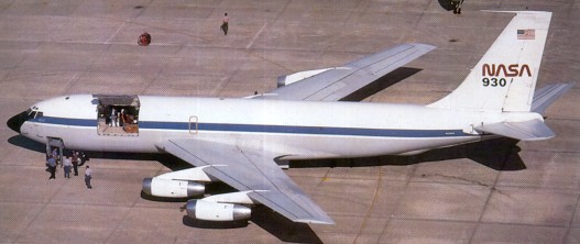
In 1967 eight standard Boeing C 135s were converted by Douglas Aircraft Company to ARIA (Apollo Range Instrumented Aircraft) EC 135Ns. Each aircraft carries inside its bulbous nose a dish shaped radar antenna to track spacecraft and lock on to them for the transmission and reception of radio messages and data telemetry between the NASA Manned Space Flight Centre at Houston, Texas, and the Apollo programme. The 707 has also been operated by the US military as the VC-135. The Navy received congressional approval to modify two Boeing NKC-135s into electronic warfare aircraft to be used for electronic warfare training of the fleet. Boeing KC/C-135 The RC 135W is derived from the RC 135M, and differs from the RC 135V in having turbofan engines. Equipment wise it is similar to the “V”, but it has a longer SLAR cheek, which cuts into the crew door area rather than stopping short of it. Also, a pair of viewing ports have been added to the overwing hatch on the RC-135W. The “V” features additional airconditioning intakes on the engine pylons. The Republic of Singapore Air Force took delivery of the first of four KC-135R Stratotankers on 10 September 1999. The former USAF KC-135A was withdrawn from ARMARC and updated with CFM56 engines and a Boeing developed multi-point refuelling system. It has bith the normal KC-135 refuelling boom and hose together with hose and drogue units under each wing.
In 1963 French KC-135 crews were being trained by SAC’s 93rd Bomb Wing at Castle AFB, California, at a rate of one four-man crew each month. France had bought 12 KC-135F which, along with crew training program, was paid under US Military assistance sales project. Training was to be completed by February 1964.
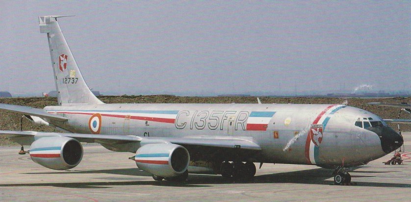
ERV-94 of the French Air Force at Istres received the last of 11 C-135FRs on 13 April 1988, serial CI (12737). Boeing converted these and equipped them with new CFM turbofans.
C-135FR serial CI (12737) on 13 April 1988
Two modified KC-135As are used by the US Federal Aviation Administration (FAA) to check navigation aids throughout the United States.
367-80 Engines: 4 x Pratt & Whitney J-57-P, 9500 lb Wingspan: 130 ft Wing area: 2400 sq.ft Length: 127 ft 10 in Height: 38 ft 3 in Empty weight: 88,890 lb Loaded weight: 190,000 lb Max speed: 630 mph Max cruise: 550 mph at 35,000 ft
KC-135A Engines: 4 x Pratt & Whitney J57-P-59W turbojet, 13,750 lb. Wing span: 130 ft 10 in (39.88m). Length: 136 ft 3 in (41.53m). Wing area: 2433 sq.ft (226.06sq.m). Max wt: 297,000 lb (134,715 kg). Typical cruise: 532 mph @ 45,000 ft. Endurance: 5.5 hr.
C-135R Engines: 4 x CFM56.
KC-135R Stratotanker Engines: 4 x CFM F108 turbofan, 22,000lb Length: 136.25ft (41.53m) Wingspan: 130.84ft (39.88m) Height: 41.67ft (12.70m) Empty Weight: 106,307lbs (48,220kg) Maximum Take-Off Weight: 322,503lbs (146,285kg) Maximum Speed: 610mph (982kmh; 530kts) Maximum Range: 2,880miles (4,635km) Rate-of-Climb: 1,290ft/min (393m/min) Service Ceiling: 41,719ft (12,716m) Accommodation: 3
RC-135M
RC-135V
RC-135W
Engines: 4 x P+W TF-33-P-5 Take-off weight: 125000 kg / 275579 lb Empty weight: 47000 kg / 103618 lb Wingspan: 39.9 m / 130 ft 11 in Length: 41.0 m / 134 ft 6 in Height: 11.7 m / 38 ft 5 in Wing area: 226.0 sq.m / 2432.64 sq ft Max. speed: 970 km/h / 603 mph Cruise speed: 650 km/h / 404 mph Ceiling: 10700 m / 35100 ft Range w/max.fuel: 14800 km / 9197 miles Range w/max.payload: 4900 km / 3045 miles Crew: 4-5 Passengers: 126
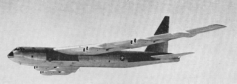
Origins of the B-52 stemmed from a specification issued through the Air Material Command (AMC) on November 23rd, 1945, calling for a long-range, intercontinental, high-altitude strategic bomber. Specifications included an operating radius of 4,340 nautical miles, a speed of 260 knots at altitude of 43,000 feet, and a bombload capacity of 10,000 pounds. In February of 1946, the Boeing Aircraft Company, Consolidated Aircraft Corporation and the Glenn L. Martin Company all responded. Boeing’s team devised the Model 462 as a straight-wing, multi-engine design powered by 6 x Wright T35 Typhoon turboprop engines rated at 5,500shp each. On June 5th, 1946, Model 462 was selected and designated XB-52. A full-scale mockup contract was then awarded.
By now, the USAAF was already looking beyond the qualities of the Model 462, fearing that the aircraft was already rendered obsolete in its conventional design approach and could never reach the intended goals of the original specification – especially in terms of its range. As such, the USAAF cancelled their contract with Boeing and the Model 462 was dead.
Boeing chief engineer Ed Wells took the Model 462 and evolved a pair of smaller concepts with four turboprops each appearing in their respective 464-16 and 464-17 forms. Essentially, the 464-16 was a short-range bomber made to carry a greater bombload while the 464-17 was a long-range bomber made to carry a smaller bombload. Neither idea stuck with the USAAF as a replacement for the B-36 though interest did center on the 464-17 design. Several more concepts were developed but interest on the part of the Air Force was waning. The Model 464-29 appeared, complete with swept-back wings at 20 degrees and fitting 4 x Pratt & Whitney turboprop engines. Again, this concept failed to answer the key points of the specification which, by now, was ever-changing to include increased performance specs along with long range.
The Model 464-35 was another Boeing design team proposal fitting 4 x turboprop engines with contra-rotating propellers. Wing sweep was increased moreso than previous attempts, beginning to define the look of the Stratofortress. With in-flight refueling becoming more of a USAF operational norm, the design team now had some leeway in the overall size of their aircraft. Events in Europe in the latter part of the 1940’s pushed the XB-52 project forward, rewarding the Boeing Company with a hard-earned contract for a single mock-up and at least two flyable prototypes.
Upon a visit to Wright-Patterson AFB by the Boeing design team, it was learned that the USAF was now more interested in a jet-powered solution, seeing it as the only way to achieve the desired performance specs it required of the XB-52. In the course of a single weekend in a Dayton hotel room Ed Wells company set to work on new ideas for a Monday morning presentation. The resulting design combined elements of their Model 464-35 design with a four-engine, jet-powered medium bomber concept that had been brought along. The new aircraft became an eight-engine, Pratt & Whitney JT3 jet-powered heavy bomber with 35-degree swept wings. A small balsa wood model was constructed to further develop the idea and accompanied a detailed Model 464-49 design document of some 33 pages. The weekend effort paid off for Boeing as the USAF became greatly interested in the aircraft after Monday morning. The design was revised into the Model 464-67 and accepted for construction as two prototypes.
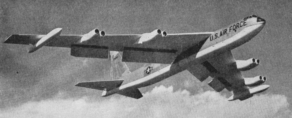
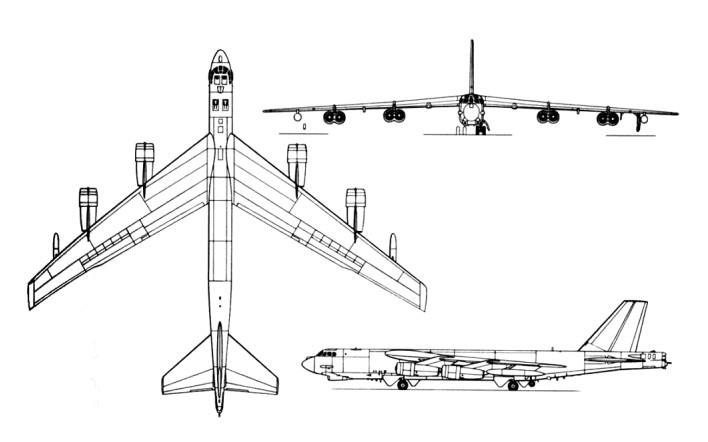
Eight engines were installed in twin pods hung under the 35 degree swept wing, and other unusual features included a vertical tail able to fold sideways to enter a hangar, wingtips that moved downwards 2.5 m (8 ft) as the wing tanks were filled, and four twin wheel landing trucks which can be swivelled for cross wind landings.
An XB-52 production contract reached Boeing executives on February 14th, 1951. The contract called for 13 B-52A models. The XB-52 became the first prototype constructed and this was followed by the YB-52. The YB-52 received this evaluation due to the funding coming from the Air Force’s Logistics Command.
The YB-52 beat the XB-52 to flight testing on March 15th, 1952. The XB-52 was rolled out on November 29th, 1951, under the cover of night for secrecy’s sake but a pneumatic system failure caused enough damage to the wing trailing edge for the aircraft to be rolled back inside for lengthy repairs. As such, the YB-52 achieved its first flight on April 15th, 1952 and did not experience any major setbacks. The XB-52 finally got airborne on October 2nd, 1952. Both the XB-52 and the YB-52 featured tandem seating cockpits with upward firing ejection seats.
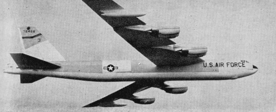
B-52A
Only 3 B-52A’s built and the B-52B and RB-52B were in large-scale production for the U.S.A.F. in 1955. Both were equipped for flight refuelling. From the original order of 13 B-52A’s, ten were later earmarked for production as B-52B models. Compared to the twin prototypes, the three B-52A’s now featured the more conventional side-by-side cockpit seating arrangement in a revised forward fuselage along with the tail armament of 4 x 12.7mm Browning M3 machine guns. A distinguishing feature of A-models to B-models was the lack of a fully operational avionics suite. These aircraft were fitted with Pratt & Whitney J57-9W engines of 10,000lbf thrust each. The split-level cockpit featured seating for three on the upper deck and seating for two in the lower. The lower occupants were given downward-firing ejection seats. The tail gunner was removed from the rest of the crew and seated in his rear-facing turret station sans any type of ejection seat though the tail system could be ejected in the event of an accident. An unpressurized crawlspace was his only link to the front of the aircraft. In-flight refueling was accomplished via a boom connection above and behind the main flight deck. Other key additions included wing-mounted external fuel tanks to increase range and decrease “wing-flexing” across the span. Water injection was introduced to the J57 to assist in take-off. The two prototypes lacked the side-by-side cockpit seating arrangement and the in-flight refueling arrangement of the A-models and seating for the third upper deck crewmember (Electronic Warfare Officer – EWO). NB-52A – aka “The High and Mighty One” – was developed from the third B-52A flight test model. This aircraft (s/n 52-0003) was modified to act as the mothership in the launching of the experimental North American X-15 aircraft. NB-52B went on to become the longest flying B-52B airframe, ultimately seeing retirement in 2004.
By 1958 weight had increased, engines were rated at 5080 or 6124 kg (11,200 or 13500 lb) thrust with water injection, and new nav/bombing systems were fitted. While original B-52’s featured a 4 x 12.7mm collection of Browning M3 heavy machine guns in a rear turret, later production models switched over to a remote-controlled 1 x 20mm M61 cannon for self-defense. The tail armament was altogether removed in more modern Stratofortress forms with the onset of the missile age. However, it should noted that at least 2 Mikoyan-Gurevich MiG-21 “Fishbed” aircraft were destroyed in the Vietnam War by the tail gunner, with these aircraft kills credited to SSgt Samuel O. Turner and A1C Albert E. Moore – both kills achieved just days apart in December of 1972 from B-52D’s. In B-52D models the tail gunner externally accessed the rear portion of the aircraft via an entry hatch. In the revised G-models, the gunner was allocated to the main crew cabin (complete with an ejection seat fitted to the upper flight deck and facing aft with the ECM operator) and operated the tail gun via the AGS-15 Fire Control System and radar.
The B-52B was, in actuality, the first true Stratofortress production model and was already in development while the previous aircraft forms were being refined. They more essentially A-models with fully operational avionics suites and Pratt & Whitney J57-P-29W, J57-P-29WA or J57-P-19W series engines all rated at 10,500lbf thrust. The J57-P-19W’s were differentiated by having their compressor blades made of titanium instead of steel. First flight of these aircraft was achieved in December of 1954. B-models were the first model in the series to achieve operational service on June 29th in 1955, this occurring with the 93rd Bombardment Wing (themselves achieving operational status on March 12th, 1956) of the United States Air Force and coming in the form of an RB-52B reconnaissance model. The defensive tail armament remained the 4 x 12.7mm machine gun mounts for a time though some 16 B-52B and 18 RB-52B models were fitted with a more potent 2 x M24A-1 20mm cannon array and an different fire control system. When this proved ineffective, the final production B-52B’s reverted back to the 4 x 12.7mm formation.
The B-52B was tested with atomic weapons on May 21st, 1956 – dropping a four megaton Mark 15 “Zombie” hydrogen bomb on the Bikini Atoll. Fifty B-52B models were produced in whole, with 27 of these being modified as special RB-52’s. RB-52’s represented reconnaissance-capable B-52B production models. These aircraft sported a crew of eight personnel and were fitted to accept specialized reconnaissance equipment in the form of a 300lb pod in their bomb bays, 40 ft fuel tanks in the wingtips, and up-rated J57 engines.
RB-52B
B-model combat load performance netted a top speed of 628 miles per hour with a service ceiling of 47,300 feet. The operational radius was equal to 3,576 miles.
The B-52C first flew on March 9, 1956 and officially came online in June of 1956 with 35 of the type seeing delivery. B-52C’s arrived with increased range thanks to improved fuel capacity made possible through larger external tanks. They were similar to B-models and operated with the same engine series. As this was the Cold War and the use of B-52’s in an all-out nuclear strike seemed all but imminent, the underside fuselage of B-52C models were painted over in an all-white scheme in an effort to reflect the thermal radiation inherent in a nuclear-induced explosion while their “tops” remained a natural metal finish. B-52B models were retrofitted with this white underside scheme. Bombloads for C-models topped 24,000lbs. B-52C’s were also reconnaissance capable though the RB-52C designation was never truly adopted for the type. Production of all C-models lasted through 1956.
B-52C
On December 7, 1955, the first B-52 built at the Wichita Division of Boeing was rolled out. This was the second source of supply.
The B-52D became the first definitive high-quantity production Stratofortress ultimately produced in 170 examples and achieving first flight on May 14th, 1956. D-models entered service in December of 1956 as dedicated long-range bombers and, unlike previous Stratofortress offerings, these aircraft would not feature the ability to carry the reconnaissance pod so there were no RB-52D designations handed out. B-52D’s were used extensively in the Vietnam air war where their expansive bomb bays could be put to good use. Vietnam-based B-52D models were distinguished by their overall forest camouflage schemes and black-colored, anti-searchlight fuselage undersides. Production was split between Seattle and Wichita plants.
In January 1957 three B-52 flew around the world non-stop refuelling mid-air several times. They covered 24,325 miles at an average speed of 530 mph.
KC-135 Stratotanker refuelling B-52
The B-52E first flew on October 17th, 1957, and followed D-models into operational service as improved Stratofortresses though they were quite similar to their predecessor. Improved air defenses across the Soviet Union forces a change to the high-level bombing strategy of early B-52’s. Therefore, the B-52E was developed into a low-level bomber. Additions included a revised bombing and navigation suite (AN/ASQ-38 – Raytheon AN/ASB-4 navigation and bombing radar) that would become standard on future Stratofortress production models. One hundred B-52E models were produced with the initial examples entering service in December of 1957. A single E-model was set aside for use as an in-flight test airframe and featured stabilizing canards.
The B-52F was similar to the preceding B-52E but sported Pratt & Whitney J57-43W series engines of 11,200lbf. Engine pods on each wing were revised to include their own water injection systems. F-models represented 89 production examples split between Seattle and Wichita to begin service in June of 1958. Among other refinements, these Stratofortresses featured new Pratt & Whitney J57-P-43W series turbojet engines. First flight was achieved on May 6th, 1958. First combat missions occurred via B-52F’s on June 18th, 1965.
While original B-52’s featured a 4 x 12.7mm collection of Browning M3 heavy machine guns in a rear turret, later production models switched over to a remote-controlled 1 x 20mm M61 cannon for self-defense. The tail armament was altogether removed in more modern Stratofortress forms with the onset of the missile age. However, it should noted that at least 2 Mikoyan-Gurevich MiG-21 “Fishbed” aircraft were destroyed in the Vietnam War by the tail gunner, with these aircraft kills credited to SSgt Samuel O. Turner and A1C Albert E. Moore – both kills achieved just days apart in December of 1972 from B-52D’s. In B-52D models the tail gunner externally accessed the rear portion of the aircraft via an entry hatch. In the revised G-models, the gunner was allocated to the main crew cabin (complete with an ejection seat fitted to the upper flight deck and facing aft with the ECM operator) and operated the tail gun via the AGS-15 Fire Control System and radar.
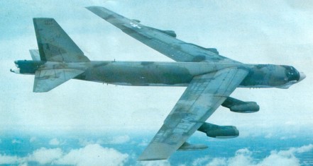
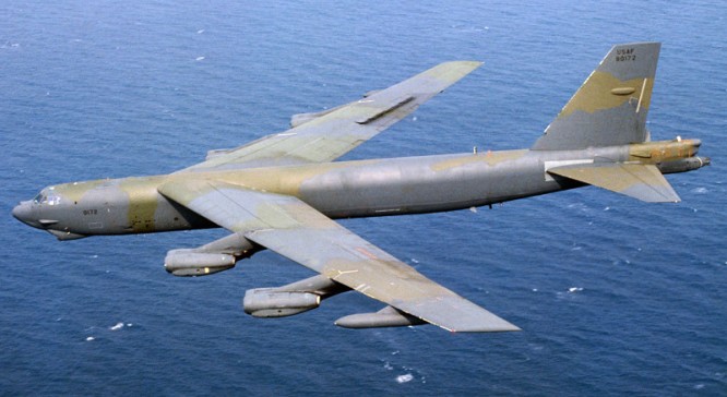
By 1959 production switched to the B 52G, with a great increase in fuel capacity, the entire crew in the nose, a new structure with a short fin, and pylons for two Hound Dog missiles. The B 52G demonstrated the range potential of the type when, in December 1960, an aircraft of the 5th Bombardment Wing flew 10,000 miles (16,093 km) in 19 hrs 45 mins. The B-52G was the most numerous version built (193).
B-52G
The B-52G introduced sealed integral tank wings housing more fuel than previous models, as well as a shorter fin and a remotely controlled tail turret. Engines: Pratt & Whitney J57, 13,750 lb. Several tons were shaved off of the aircraft and crew accommodations were improved. The tail gunner was relocated to a new station within the main cabin area in the forward fuselage where the rest of the crew resided and given remote control of the turret. The vertical tail fin was shortened while the nose radome was lengthened and ailerons completely eliminated in favor of seven spoilers to provide for roll control. The G-model first flew on August 31st, 1958 and entering service on February 13th, 1959. G-models (55th production onwards) were outfitted with underwing pylons to accept the AGM-28/GAM-77 Hound Dog nuclear-tipped cruise missile – a feature also retrofitted on earlier production G-models. The Hound Dog missles could be run during takeoff to shorten the takeoff run. These Superfortresses were also later cleared to use 20 x AGM-69 SRAM nuclear missiles beginning in 1971. Four ADM-20 Quails (aircraft shaped decoys) were added in the bomb bay. Many B-52G’s would be sacrificed as part of the nuclear proliferation agreements between the United States and the Soviet Union beginning in 1992 while the surviving models were relegated to museum work. Production of G-models was handled by Wichita. The first 16 B-52Gs with cruise missiles became operational in December 1982.
The B-52H model was first flown on March 6th, 1961 and introduced into service on May 9th, 1961. The B-52H model and designed to carry the GAM-87 Skybolt ballistic missile on four external pylons. Though essentially similar to the G-models it replaced, the B-52H sported improved performance and fuel efficient Pratt & Whitney TF33-P-3 turbofan engines of 17,000lbf and a reinforced understructure for improved low-level bombing. Major systems and subsystems were revised or improved as well and the 4 x 12.7mm tail gun armament was officially replaced by the remote-controlled 1 x 20mm General Electric M61 Vulcan six-barrel Gatling cannon system (6,000rpm) tied to an Emerson ASG-21 fire control system. Ammunition supply was 1,242 rounds. The B-52H went on to utilize cruise missiles (the Skybolt missile was eventually cancelled before production), anti-ship missiles and unmanned drones in this fashion thanks to its heavy duty wing pylons. Light duty pylons were added later between the two engine pods on either wings and retrofitted to earlier H- and G-models. Like her G-model sisters, B-52H’s were cleared to use 20 x AGM-69 SRAM nuclear missiles beginning in 1971. Low-level operations became another improvement of this model type. The last of 102 B 52H bombers was delivered in 1963, bringing production to 744. The B 52H has the much more powerful TF33 engine, eliminating water injection and instead of four 12.7 mm (0.5 in) tail guns has a six barrel cannon. Surviving B 52Gs and B 52Hs are continually being fitted with updated systems for service into the second half of the 1980s.
Over a three-year period to 1963, the USAF spent $825 million on B-52 rework.
A total of 99 B-52Gs, carrying 12 external AGM-86B air-launched cruise missiles (ALCM), and 96 B-52Hs with 12 external and, later, eight internal ALCMs, were to be operational by 1990. The B-52Hs were to receive internally mounted common strategic rotary launchers (CSRL) in the late 1980s to carry the ALCMs, SRAMS, advanced cruise missiles, and free-fall nuclear weapons. The first ALCM equipped B-52G unit became operational in December 1982. Cruise-missile-carrying B-52Gs are being fitted with a strakelet fairing at the wing root leading edge for indentification purposes under the unratified SALT II agreement.
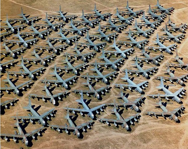
Most of the early B-52s were phased out by 1970, due to Secretary of Defense Robert S. McNamara’s mid-sixties decision to decrease the strategic bomber force.
Numerous B-52s were rebuilt with a ‘Big Belly’ to carry 84 bombs inside, plus 24 on triple tandem pylons under the wings. Modified B-52Ds, referred to as Big Belly, dropped aerial mines in the North Vietnamese harbors and river inlets in May 1972. In December of the same year, B-52Ds and B-52Gs began to bomb military targets in the Hanoi and Haiphong areas of North Vietnam.
A total of 744 were built between 1954 and 1962, including the XB-52 and YB-52 test models. During its peak involvement with Strategic Air Command, no fewer than 650 B-52 bombers made up 42 SAC bomber squadrons at 38 bases. In 2010, the Air Force maintains approximately 76 active and 20 reserve B-52’s from the 744 total that were produced. Production of all B-52’s lasted from 1952 through 1962 and handled at the Boeing Seattle, Washington and Wichita, Kansas plants.
A world air speed record was set on September 26th, 1958, in a B-52D reaching 560.705 miles per hour on a closed circuit covering 6,210 miles. The same day netted another air speed record of 597.675 miles per hour over a 3,105 mile course. On December 14th, 1960, a B-52G set a world air distance record by traveling 10,078.84 miles without refueling. This record was bested several years later on January 10th/11th, 1962, when a B-52H achieved 12,532.28 miles of unrefueled flight time in a journey from Japan to Spain. According to Boeing, this single flight alone broke some 11 speed and distance records.
The B-52 has also made it into pop culture as it was the aircraft featured in the 1964 Stanley Kubrick film “Dr Strangelove”.
B-52A Long-range heavy bomber. Engines: 8 x Pratt & Whitney J57-P-3 turbojets, 10,000 lb thrust Wingspan: 185 ft Lenght: 156 ft Wing area: 4000 sq.ft Loaded weight: approx. 400,000 lb. Max speed: approx. 650 m.p.h. Ceiling: 50,000 ft. Typical range: 6,000 miles with 25,000 lb bombs Armament; 4 x.50 in. machine-guns in tail-turret.
RB-52B Engines: 8 x Pratt & Whitney J57-P-3, 9700 lb Wingspan: 185 ft Length: 156 ft 6 in Height: 48 ft 3.5 in Wing area: 4000 sq.ft Empty weight: 175,000 lb Loaded weight: 350,000 lb Max speed: 630 mph Service ceiling: 50,000 ft Normal range: 3000 mi (with 75,000 lb bombload) Max range: 6000 mi (with 25,000 lb bombload) Armament: 2 x 20mm tail gun
B-52D Engines: 8 x Pratt & Whitney J57-P-29WA turbojet, 12,100 lb thrust. Armament: 4 x .50in mg. Bomb load: 27216 kg (60,000 lb). Range: 7400 sm / 11,860 km
B-52G Engines: 8 x Pratt & Whitney J57-P-43W turbojet, 11,200 lb, 49835 N thrust. Wing span: 185 ft 0 in (56.39 m). Wing area: 4000 sq.ft Length: 157 ft 7 in (48.03 m). Height: 40 ft 8 in (12.4 m). Armament: 4 x .50in mg. Max TO wt: 480,000 lb (217,720 kg). Max level speed: 660 mph (1062 kph) at 20,000 ft Range: 6480 nm / 12000 km Armament: 4x MG 12,7mm Bombload: 22680kg
B-52H Engines: eight Pratt & Whitney TF33-P-3/103 turbofans, 75.62 kN (17,000 lb st) Length 49.05m (160 ft 11 in) Height: 12.40m (40 ft 8 in) Wing span: 56.39m (185 ft 0 in) Wing area: 371.6 sq.m (4,000.0 sq ft). Empty weight: 83,250 kg (185,000 lb) Max Take-Off Weight: 229,088 kg (505,000 lb) Fuel capacity: 312,197 lb (141,610 kg), 47,975 U.S. gal (181,610 L) After inflight refuelling weight: 256738 kg (566,000 lb). Maximum speed Mach: 0.86, 1045 km/h (650 mph) Cruising speed high altitude: Mach 0.77, 819 km/h (509 mph) Penetration speed low altitude: 652-676 km/h (405-420 mph) Service ceiling: 16,765m (55,000 ft) Combat ceiling: 14326 m (47,000 ft). Range at high altitude with bombload: 16300 km (10,130 miles). Armament: up to 22,680 kg (50,000 lb) of ordnance, one Vulcan T 171 six barrel radar-directed 20mm cannon Crew: 6 102 built.
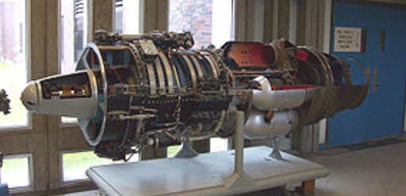
The Avro Canada TR.5 Orenda was the first production jet engine from Avro Canada’s Gas Turbine Division. Similar to other early jet engines in design, the Orenda outperformed its rivals in most ways, and the Orenda-powered Canadair Sabres were among the fastest of all first-generation jet fighters. Over 4,000 Orendas of various marks were delivered during the 1950s, Avro’s greatest engine success.
The Orenda design started in the summer of 1946 when the Royal Canadian Air Force (RCAF) placed an order with Avro Canada for a new night/all-weather fighter. To power the design, Avro decided to build their own engines. Avro had recently purchased Turbo Research, a former crown corporation set up in Leaside, Toronto, to develop jet engines.
Turbo Research was in the midst of designing their first engine, the 3,000 lbf (13 kN) TR.4 Chinook, which could easily be scaled up for the new fighter design. It was decided to continue working on the Chinook to gain experience even though they had no intention of producing it.
As work on the Chinook continued, Avro’s newly christened Gas Turbine Division started work on the larger 6,000 lbf (27 kN) thrust design needed for the RCAF contract. Winnett Boyd started detailed design in autumn 1946, and a formal contract was received in April 1947. The only major change was the addition of a tenth compressor stage of stainless steel, and changing the third stage from aluminum to steel as well. The design work was completed on 15 January 1948, just prior to the first run of the Chinook on 17 March 1948. During the design Joseph Lucas of the UK was contracted to help with the combustion design, which led to a slight delay as they recommended using a longer combustion chamber than originally designed. The resulting TR-5 was named “Orenda”, an Iroquois word meaning “Tribal Soul on the Right Path”.
Given the experience of the Chinook, and the fact that the two designs were similar in many ways, progress on the Orenda was rapid. Parts started arriving in 1948, and the first engine was completed and run for the first time on 8 February 1949. Avro was so confident of the design that they invited high-ranking officials from the RCAF and Canadian government to witness this very first test, which went off without a hitch after fixing a minor electrical problem. Within two months the engine had already passed 100 hours of running time, and on 10 May had reached its design thrust of 6,000 lbf (27 kN). At the time, it was the most powerful jet engine in the world, although it held this record only briefly until the Rolls Royce Avon RA.3 was introduced the next year.
By 1 July it had passed 500 hours, and had run for 477 of these before requiring a rebuild. In September it was on its way to 1,000 hours when a technician’s lab coat was sucked into the engine, complete with a set of razor blades in his pocket. From then on testing was carried out with a set of metal rings in the intake to avoid ingesting foreign objects. After repairing the damage the engine returned to testing, now joined by two further examples of the Orenda 1. Together they passed a total of 2,000 hours by 10 February 1950. By this point a problem with fatigue cracks in the seventh and eighth stages had become apparent, which required them to be redesigned and made much thicker. This solved the problem, and by July they had passed 3,000 hours.
Flight testing started with a converted Avro Lancaster, FM209, one of the many Mk.10’s built at the Victory Aircraft plants during the war. The two outboard Merlin engines were replaced with the Orendas, and the new aircraft took to the sky on 10 July. Avro test pilots had much fun flying the aircraft across Lake Ontario to the Buffalo, New York area, where they were able to easily outperform the P-47 Thunderbolt’s of the Air National Guard that were sent to investigate. In one incident at an airshow, all four engines were turned off by mistake, but the Orenda’s quick start time allowed them to recover. The aircraft ran up 500 hours by July 1954, when this portion of flight testing ended; it was destroyed in a hangar fire on 24 July 1956.
The Orenda 2 was the first production model, passing its qualification tests in February 1952. This version showed additional cracking in the ninth stage, and had to be strengthened like the earlier model. Even before being qualified, the engine had been fitted to the Avro CF-100 and flown on 20 June 1952, with a squadron of pre-production Mk.2 aircraft entering RCAF service on 17 October. The Orenda 3 was similar, but had a number of modifications to allow it to be mounted in the Sabre in place of the J47. One example was produced and sent to North American Aviation.
The first real production model was the Orenda 8, which was the powerplant of the CF-100 Mk.3. This model was first flown in September 1952 and entered service in 1953. This was soon followed by the Orenda 9 powered Mk.4 that flew on 11 October 1952, and then by the rocket-armed Mk.4A with the 7,400 lbf (33 kN) Orenda 11. The Orenda 11 demanded higher airflow through the engine, and featured a second turbine stage to power the more powerful compressor. The 11 would be the primary production version for the CF-100, powering the Mk.4A and all future versions, with over 1,000 engines produced.
While work on the CF-100 continued the RCAF also started looking at a new day fighter, eventually selecting the Sabre. A single Sabre 3 was built with the Orenda 4 engine, with performance similar to the US models. Production then turned to the Sabre 5 with the Orenda 18, and then to the Sabre 6 with the Orenda 11-derived 7,275 lbf (32,360 N) thrust Orenda 14. The resulting Sabre was both lighter and more powerful than its J47 powered counterparts, and went on to set a number of air speed records. Most notable among these was Jacqueline Cochran’s supersonic flight in the sole Sabre 3, which Canadair lent to her for the effort. Canadair built 1,815 Sabres in total, 937 of these equipped with Orendas. Several examples, notably one at Boeing, serving into the 1970s.
The engine was so successful that the Gas Turbine Division was renamed Orenda Engines when Hawker Siddeley reorganized their Canadian operations in 1955.
The Orenda was fairly conventional in layout, built in three main parts; compressor, combustion area, and turbine/exhaust.
At the front was the compressor section, containing the ten-stage compressor housed in a tapering magnesium alloy shell. The shell was machined with grooves that held the stators. At the front of the compressor was an intake fairing with a prominent “nose cone” containing the front main bearing. Four guide vanes held the cone in place, with a power takeoff shaft running inside one of them to power the top-mounted accessories section. The nose cone also held the electric starter motor, which acted as a generator once the engine was up and running. The engines used on the CF-100 also contained a uniquely Canadian invention, two prominent winglettes at the very front that sprayed alcohol into the intake as a de-icing system. The CF-100 versions also mounted the debris cage, mentioned earlier.
The compressor had ten axial stages of mixed steel and aluminum construction. In the original Orenda 8, 9 and 10’s this operated at a 5.5:1 compression ratio, compared to about 3.5 for wartime designs. The hub consisted of three aluminum disks carrying the first nine stages, and a steel disk bolted onto the end carrying the tenth. The central casing held the power shaft and was made from magnesium alloy. Around it were the six flame cans. The turbine was made of solid Inconel blades attached to an austenitic steel hub. The blades were air cooled by bleeding off compressed air from the fifth compressor stage and piping it to the turbine face, the six pipes lying between the flame cans. The exhaust section consisted of welded steel sheeting.
Variants: Orenda 1 – original prototype models, 6,000 lbf (27 kN) Orenda 2 – first production model Orenda 8 – improved reliability, 6,000 lbf (27 kN) Orenda 9 – improved thrust, 6,500 lbf (29 kN), required some changes to the nacelles Orenda 10 – Orenda 9 adapted for the Sabre Orenda 11 – main production version for the CF-100, 7,400 lbf (33 kN) Orenda 14 – similar to the 11, 7,275 lbf (32.36 kN), used on both the CF-100 and Sabre Orenda 17 – combined the compressor from the 9 with the turbine of the 11, along with an afterburner 8,490 lbf (37.8 kN) wet
Specifications:
Orenda 9 Type: Turbojet Length: 10 ft 1 in (3.07 m) Diameter: 3 ft 6 in (1.07 m) Dry weight: 2,650 lb (1,200 kg) Compressor: 10-stage axial flow Combustors: can type, 6 Fuel type: Kerosene Maximum thrust: 6,500 lbf (29,000 N) at 7,800 rpm
The Royal Canadian Air Force, needed an all weather fighter to defend the vast dominion and after talking with the American and British air staffs decided to write its own specification, issued in October 1946. It called for a fighter having a crew of two, advanced radar, all weather and night equipment, heavy gun armament, the ability, to operate from advanced air¬bases with austere ground equipment and runways only 4,000ft long. Plus a combination of speed, rate of climb and range never before attained in any combat aircraft.
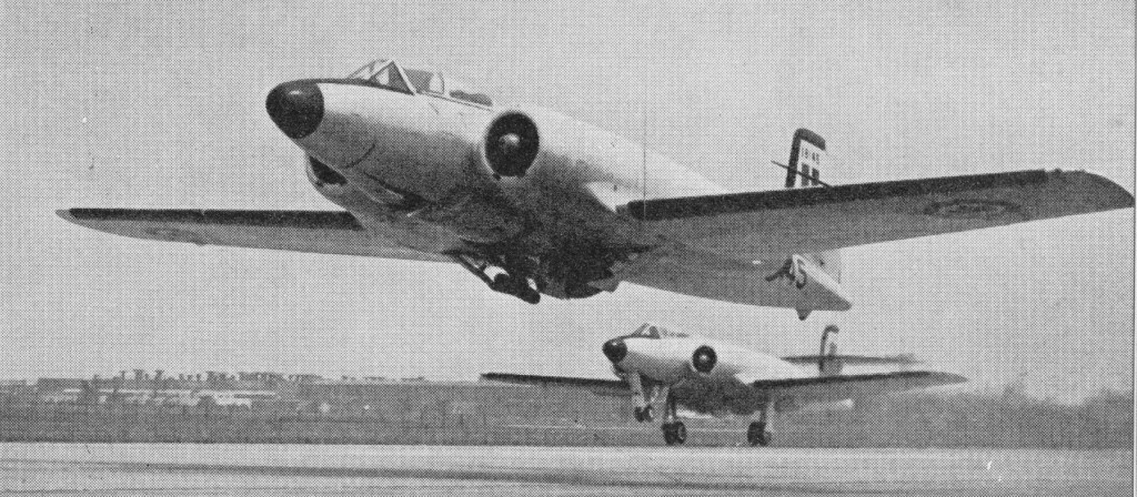
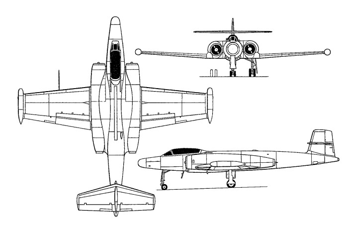
Design of the two-seat all-weather long-range fighter was initiated in October 1946, the Avro Canada team under E. H. Atkin, chief engineer, settled for a long slim fuselage, low unswept wing of quite high aspect ratio, and twin engines on the sides of the fuselage above the wing. The Avro scheme made the engines higher off the ground, but still easy to service and not difficult to change. The steerable nose gear and main legs all had twin wheels. The first of two prototype CF-100 Mk Is (No 18101, FB-D) was flown on 19 January 1950, both of these aircraft being powered by Rolls-Royce Avon RA 3 turbojets, each of 2948kg thrust. Although not designed for speeds over Mach 0.85, it was taken supersonic during a dive by test pilot Janus Żurakowski in December 1952.
It was a low-wing cantilever monoplane of all metal construction, the tail unit incorporating a tailplane and elevators mounted mid-way up the fin. The retractable tricycle landing gear had twin wheels on each unit, and accommodation for two, in tandem, was in a pressurised cockpit. All control surfaces were fully powered. Large airbrakes were fitted above and below the wing ahead of the flaps. Pilot and navigator sat in tandem Martin Baker seats.
CF-100 Mk.1
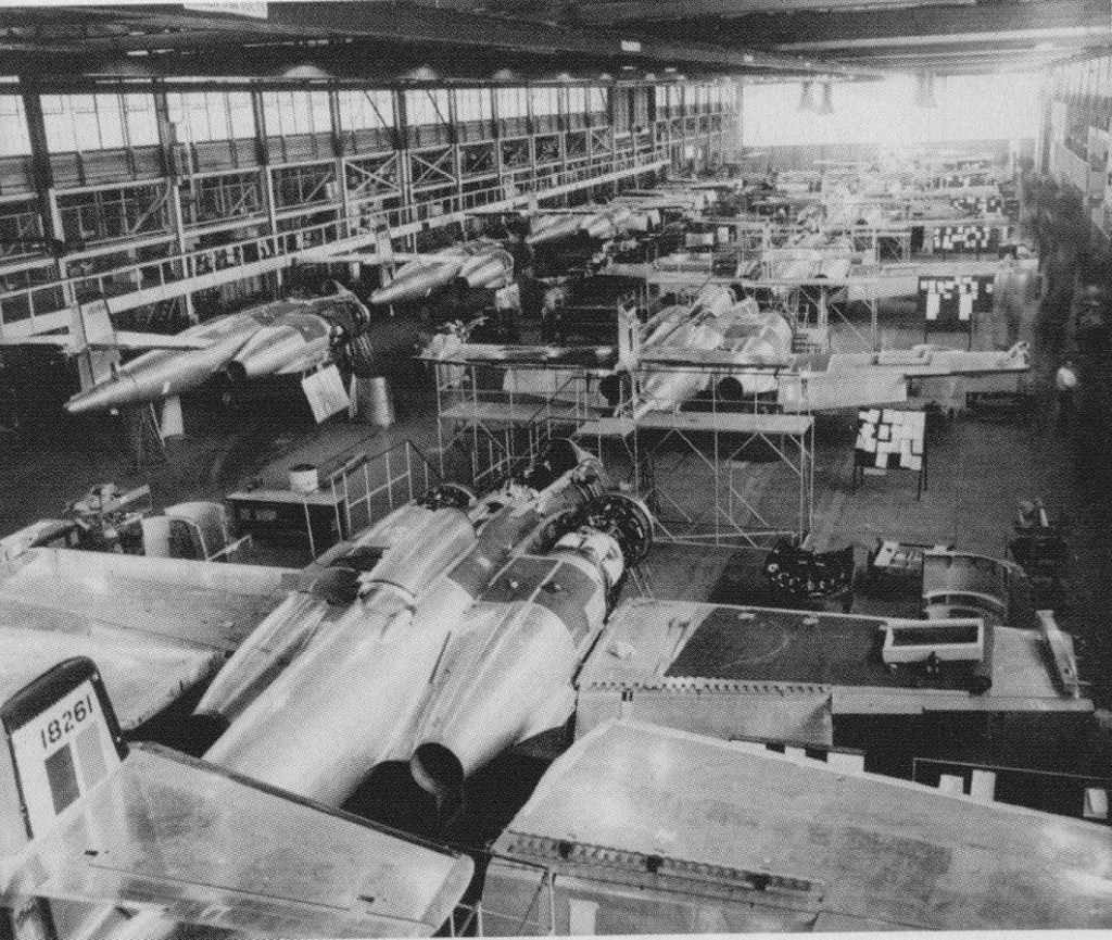
Successful testing of the prototypes led to an order for 10 unarmed pre-production CF-100 Mk 2s, these being the first examples to be powered by 2722kg / 6,000 lb thrust Orenda 2 turbojets, built by the engine division of Avro Canada. When the first of these CF-100 Mk 2s made its maiden flight, on 20 June 1951, it was the first aircraft that had been completely designed and built in Canada. One of this pre-production batch was equipped as a dual-control trainer, becoming designated CF-100 Mk 2T, and another example from this batch was the first to enter service with the RCAF, on 17 October 1951.
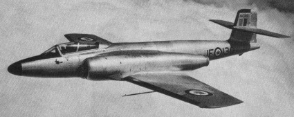
Orders followed for 124 production aircraft designated CF-100 Mk 3 in September 1950, named Canuck by the RCAF, and the first of these entered service soon after a first flight in early September 1952. They differed by having Orenda 8 turbojets of 6,000 lb thrust (of similar output to the Orenda 2s), carried eight 12.7mm Colt-Browning machine-guns in a ventral pack, which could be winched in or out of the fighter as a unit, and were equipped with nose-mounted AN/APC -33 radar. The Mk 3 entered service with No 445 Squadron at North Bay, Ontario, in 1953. A total of 70 of this version was built before production switched to the definitive CF-100 Mk 4, and once the Mk 4 became available in 1954, most of the remaining Mk 3’s were either used at the Operational Training Units or converted to dual control trainers. 50 were converted to CF-100 Mks 3CT and 3DT trainers.
CF-100 Mk.3A
In 1951, in partnership with Hughes Aircraft, Avro Canada completely replanned the CF 100 with the new armament. The tenth CF 100 Mk 2 was chosen as the aircraft to develop the new system, making its maiden flight as the prototype Mk 4 on October 11, 1952, the same day as the first production Mk 3. The nose was longer and fatter, and instead of the APG 33 gunsight radar of the Mk 3 there was a radome for the MG 2 (E4) fire-control radar. The standard Mk 4 retained the gun pack but added wing tip pods each housing either 29 or 30 Mighty Mouse rockets, the same FFAR (folding fin aircraft rocket) of 2.75in calibre as standard on the, USAF interceptors. The Mk 4 had collision course fire control, the new interception method in which the radar and autopilot interlinked to steer the aircraft automatically to launch the rockets in a salvo to pass through a “box” of sky at the same time as the hostile aircraft. It freed interceptors from the need to attack from behind, and in a side on interception gave a much better reflective target for the radar.
The last 54 aircraft were cut from the Mk 3 order, holding production of this model to 70, while orders for the Mk 4 were repeated until they reached the total of 510. It was the RCAFs standard all weather fighter in 1953 59 and continued to serve, into the 1960s after modification to Mk 5 standard. Early Mk 4s were styled Mk.4A and fitted with the Orenda 9 rated at 6,500 lb, and visually distinguished by the free spinning two-blade windmill on the inlet bullet from which alcohol anti icing fluid could be sprayed. The Mk 4B was fitted with the Orenda II of 7,275 lb thrust, and most 4Bs were also fitted with all-rocket armament, the gunpack being replaced by a retractable box containing a further 48 FFARs launched in salvo by hydraulically extending the box briefly into the airstream. A further modification in most 4As and all 4Bs was that the large canopy was blown from a single sheet of Plexiglas.
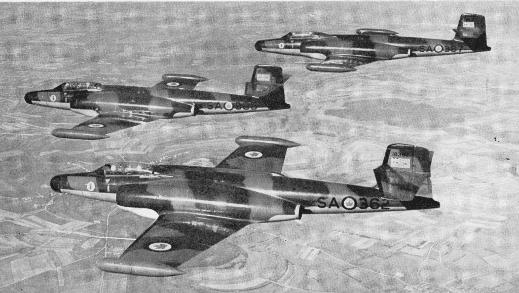
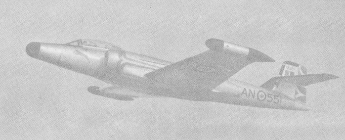
CF-100 Mk.4B No.445 Sqn RCAF, Marville, France 1957
The first production Mk 4 flew on October 24, 1953. The Mk.4 version was redesignated CF-100 Mk 4A after the introduction of a generally similar CF-100 Mk 4B that differed primarily by having more powerful Orenda 11 turbojets, each of 3300kg thrust.
Unofficially known as the Canuck, the CF-100 Mk 4A was the first CF-l00 to be fitted with AN/APC-40 radar and was powered by the 2948-kg (6,500-lb) thrust Orenda 9 turbojet engine, which was replaced by the slightly more powerful Orenda 11 on the CF-100 Mk 4B model. Armament in both cases took the form of eight 12.7-mm (0.5-in) machine-guns backed-up by 104 70-mm (2.75-in) rockets carried in the distinctive wing-tip pods. Production of CF-100 Mks 4A and 4B totalled 134 and 144 respectively, being followed by the CF-100 Mk 5 production version.
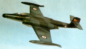
The CF-100 Mk 5, which featured an extended wing span and updated equipment, was lighter for it lack-ed the machine-guns of earlier variants, relying solely on rockets for interception. Aimed entirely at increasing high altitude manoeuvrability, the Mk 5, the first of which flew on October 12, 1955, had just over 3.5ft added on the end of each wing, the new sections having constant chord. Tailplane area was also slightly increased, and among less basic changes was the introduction of a larger wingtip pod housing 52 FFARs, making (with the centreline pack) a maximum of 152. No Mk 5s were built new, the 100 aircraft for inventory being converted while the final 4Bs were still on the assembly line, 53 of which were supplied to Belgium, based at Beauvechain, these being the only CF-100s to be exported.
The first production example flew on 12 October 1955.
CF-100 Mk.5
In addition, a substantial number of CF-100 Mk 4s were up-dated to the later configuration for service with squadrons of the then Royal Canadian Air Force in both Canada and Europe. The CF-100’s operational career as an interceptor came to an end in the early 1960s, but a few aircraft were further modified to act as electronic aggressors in evaluating the performance of Canada’s defences. Known as CF-100 Mk 5C and CF-100 Mk 5D aircraft, these were finally retired by No. 414 Squadron in late 1981.
On November 4, 1956, No 445 Squadron brought its Mk 4Bs to Europe to add all¬-weather defence to AAME (Allied Air Forces Central Europe), and until 1962 four RCAF squadrons of 4Bs and 5s operated from the Gros Tenquin/ Marville, / Zweibrücken / Baden Söllin¬gen complex as the all weather com¬ponent of the 1st Air Division. So reliable were the Canadian fighters¬ ¬that the Belgian Air Force purchased 53 ex RCAF Mk 5s and took delivery from December 1957. By this time all CF 100s in front line service had green/grey camouflage, the Belgians merely changing the national markings. Though the added wing sections caused structural problems at high indicated airspeeds the Mk 5 remained an adequate all weather platform well into the 1960s.
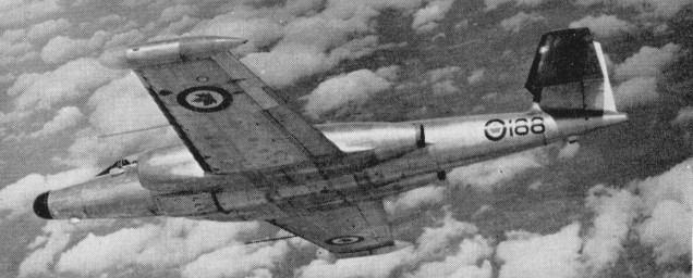
The Avro CF-100 “Canuck” was the RCAF’s second operational jet fighter replacing the de Havilland Vampire. They patrolled the skies over North America and Western Europe from 1953-1981. The aircraft last served with No. 414 “Black Knight” squadron (electronic warfare unit) at North Bay, as a Mark 5D ECM (electronic counter measures aircraft).
A total of 692 aircraft were produced in the different variants, and the CF-100 was world’s first straight-wing combat aircraft to exceed Mach 1 (in a dive, 18 December 1952). Many innovations in radar and quick-change weapons were developed on the CF-100, and some of its design features were incorporated in the Avro Arrow.
A. V. Roe Canada CF-100 Mk.1 All-weather fighter Engines: 2 x 6,500 lb. thrust Avro Orenda 9 turbojets. Wingspan: 58 ft 5 in Length: 54 ft. 4 in Loaded weight: 34,000 lb. Max. speed: over 650 m.p.h. Max. range: 2,000 miles. Armament: 132x.2.75 in. rockets. In retractable pack under fuselage and wing-tip containers. Crew: 2
CF-100 Mk 3D dual trainer Engines: Two Orenda 8, 6000 lb thrust axial flow gas turbine Maximum speed: Mach .85 Empty weight: 23,000 lb (10 432 kg) Maximum weight: 34,000 lb (15,436 kg) Span: 57 ft 6 in (17.5 m) over tip tanks Length: 52 ft 3 in (15.9 m) Height: 14 ft 6 in (4.4 m)
CF-100 Mk 4 Engines: 2 x 2948kg thrust Orenda 9
CF-100 Mk 5 Engines: 2 x turbo-jet Orenda 11 or 14, 32.3kN, 3300-kg (7, 275-lb) Max take-off weight: 16330 kg (36,000 lb) Empty weight: 10478 kg / 23100 lb Wingspan: 18.54 m (60 ft 10 in) Length: 16.48 m / 54 ft 1 in Height: 4.74 m / 16 ft 7 in Wing area: 54.9 sq.m / 590.94 sq ft Wheel track: 10 ft 2 in Wheelbase: 18 ft 1 in Maximum speed 1046 km/h (650 mph) at 3050 m (10,000 ft) Initial climb rate 2591 m (8,500 ft) per minute Service ceiling: 16460 m / 54000 ft Range w/max.fuel: 3220 km / 2001 miles Range w/max.payload: 2072 km / 1288 miles Combat radius 1046 km (650 miles) Armament: 29 x 70mm missiles in each of wing containers Crew: 2