LTV F8U / F-8 Crusader / V-392

RF-8A Crusader

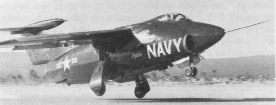
In September 1952 the US Navy issued a required for a fighter that could fly faster than the speed of sound and operate from a carrier. The RFP (Request For Proposals) was issued to eight different aircraft manufacturers. A total of 21 proposals were submitted. In May 1953 the US Navy selected the V-383 by Chance-Vought as the winner. Two prototypes were built and designated XF8U-1. Shortly after the US Navy also ordered the V-392 which would become known as the F8U-1P.

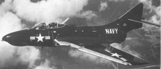
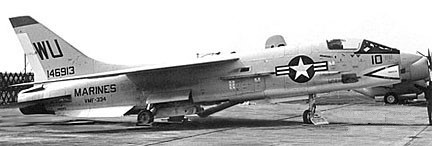
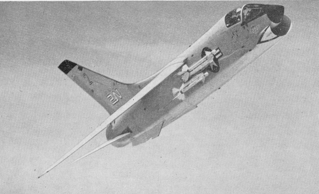
The design features a high mounted, variable incidence wing which can pivot upwards to permit lower landing speeds. Originally a dayfighter but later variant were also capable of flying all-weather operations. The Crusader is considered to be a dogfighter, equipped with four 20mm cannons as it primary weapons and two or four short range air-to-air missiles like the AIM-9 Sidewinder as secondaries.

LTV Aerospace Corp F-8 Crusader Article

On March 25 in 1955 the first prototype took off from Edwards AFB for its maiden flight. On this first flight the aircraft went supersonic.

The first production Vought F-8A Crusader went to the Navy’s VF-32 squadron in March 1957 and these first went to sea on board USS Saratoga.

On March 25 in 1955 the first of two prototypes (138899 & 138890) took off from Edwards AFB for its maiden flight piloted by John Konrad. On this first flight the aircraft went supersonic.

Vought XF8U-1

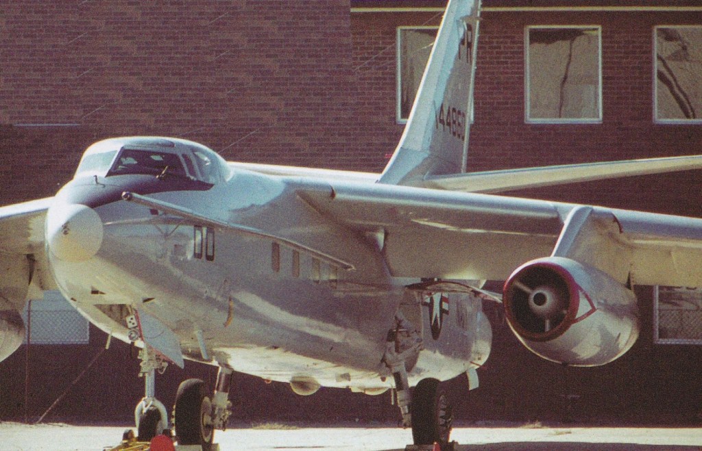
First production was F8U-1 (re-designated F-8A in 1962), first flying on 30 September 1955. 593 were built; 138899 & 138900, 140444-140448, 141336-141363, 142408-142415, 143677-143821, 144427-144625, 145318-145545, 145604-145647, and 146822-146905.

The first production Vought F-8A Crusader went to the Navy’s VF-32 squadron in March 1957 and these first went to sea on board USS Saratoga.

Vought F8U-1

F8U-1D, re-designated DF-8A, were control aircraft for Regulus missiles and the DF-8F target drone controller.

Shortly after the production of the F8U-1 started, the first unarmed photo-recon F8U-1P flew on December 17, 1956 and it was the F8U-1P that did low-level photo reconnaissance during the Cuba crisis. 144 of the 1957 F8U-1P / RF-8A were built; 141363, 1446507-144625, 145604-145647, and 146822-146901.

The F8U-1 was followed by an improved variant, the F8U-1E, which had an improved APS-67 radar system (and so a bigger plastic nose-cone), giving it limited all-weather capability. The first F8U-1E – a modified production F8U-1 – flew in early September, 1958

Vought F-8E VF-51 149149

A total of 218 F8U-1s and 130 F8U-1Es (145416-145545) were built before production switched in September of 1958 to the F8U-2

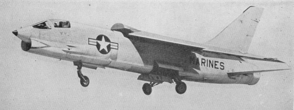
The YF8U-2 prototype flew for the first time on August 20, 1957. It was powered by a new and more powerful engine, a J57-P-16 with afterburner. The new engines also needed additional cooling. The F8U-2 could be fitted with up to four instead of two Sidewinder missiles. However, the four-missile armament was only very rarely carried in combat, since pilots felt that the extra weight and reduction in fuel load was not worth the two extra missiles. The F8U-2N was a limited all-weather interceptor version of the Crusader. The ‘N’ stood for night, because this version was intended to become a true night fighter. It was equipped with the even more powerful J57-P-20 engine and an approach power compensator (APC). The APC made the carrier landings a lot easier and saver. A total of 152 were built between June 1960 to January 1962 and served also with the US Marine Corps. The US Navy F-8D’s were however quickly replaced by the F-8E. The F-8E entered service in September 1961.

The F8U-2, F-8C, -8D, -8E, and -8J featured new fire-control and APQ-94 radar systems, and 10700 lb P&W J57-P-16/-20 engines. First flown on 20 August 1958, 625 were built; 145546-145603, 146906-147077, 147896-147925, 148627-148710, 149134-149227, 150284-150355, 150654-150683, and 150843-150932] included suffixes F8U-2N/F-8D (all-weather with APQ-83 radar) and F8U-2NE/F-8E (with APQ-94 radar); plus 42 as F-8E(FN) for the French Navy (151732-151773). The F-8E was developed further with J57-P-20 as the F-8J, with complications.

Vought F-8C USMC VMF-334 146913

The intent of the F-8J was to improve the F-8E with better radar, tail armament in the form of armor plate protection for the UHT actuators, better cruise and landing flight characteristics with 2-section leading edge droops and BLC, improved approach power compensator with a UHT rate input, improved ECM and wing pylon fuel drop tank capability. There were a few more things, like new wiring, UHF radio, and APR-30 RWR gear. But the plane was rushed to the fleet with only limited carrier-suitability testing.

Squadrons on the Ticonderoga and Bon Homme Richard got to be the carrier-suitability testers for the fleet by default.

The aircraft was woefully overweight by almost 2000lb and underpowered. With BLC on you lost about 800 lb of thrust. Flight control rigging was optimized to achieve the slowest approach speed with apparently little consideration for anything else. The result was a dangerous aircraft around the boat, especially at night. Although approach speeds were down around the 120-kt range at max trap weight, you couldn’t see over the nose, and wave-off capability was pathetic. Squadrons tried various things to deal with the poor wave-off performance.

The Tico played with “trim drag” by altering the c/g of the aircraft through fuel management. They would intentionally leave fuel in the aft cluster for this purpose. The Bonny Dick placed limits on temperatures that we could fly using 90° for day and 85° for night. (They promptly installed a thermometer that could be read in tenths, and at 84.9° at night we would launch.) We also were taught the “pulse technique” wave-off. For this you would rotate the aircraft to almost a stall while simultaneously applying full power. With the sink rate halted, you would then ease off and climb out. Imagine that maneuver at night!

To add to your worries, you could actually fly the airplane below the minimum speed required to operate the RAT (Marquardt emergency Ram-Air Turbine). The thought that you could be on final at night, operating off the RAT, and then lose all electrical power was frightening, to say the least.

Gradually, during the cruise, Navair responded to the problems and sent teams to WestPac to begin incorporating the fixes. To relieve the weight problem, armor plate in the tail was removed and the ALQ-51 was re-installed to replace the newer, but heavier, ALQ-100. Visibility over the nose was improved by changing the flight control rigging and increasing the approach speed to around 128 kts. The RATs were reworked to allow for safe operation at approach speeds. Wave-off capability was improved by incorporating a “War Emergency Thrust” throttle position — a spring was added to the leading edge of the throttle quadrant that would stop the throttle at the MRT position unless you pushed it further against the spring and into the WEP position. We were instructed to get used to using WEP by practicing during fouled-deck waveoffs until the first engine hot section inspection showed that we were destroying the engine’s burner cans. It seems that WEP was just intentionally allowing you to overspeed the engine for additional power, and it played hell on the burner cans.

The ultimate fix came with the improved J57-P-400 series engines about a year later. Eventually, Navair made all the necessary mods, and the -8J served well until its retirement. (Jack Musitano 02/01/00)

On September 18, 1962, the Crusader F8U was redesignated F-8 under the new unified Tri-Service designation scheme.

The F8U-2N first flew on 16 February 1960 and deliveries began to the US Navy commenced later that year.

F8U-2N

The F-8E or F-8FN Crusaders was the French version of this successful dogfighter and remained in service with the French Navy until the end of 1999 to be replaced by the Rafale-M. A total of 1305 Crusaders were built.

F-8E(FN)

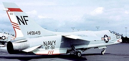
The F8U-2NE or later designated F-8E was the final production version of the Crusader for the US Navy. It was an improvement of the F8U-2N with a new and even larger APQ-94 search and fire-control radar that gave it improved all-weather capability. The F8U-2NE differed from previous Crusaders in having a substantial air-to-ground capability. A total of 286 F-8Es were built until the end of the summer of 1964. It was the E model of the Crusader that was responsible for the greatest number of Crusader MiG kills in Vietnam

F8U-3

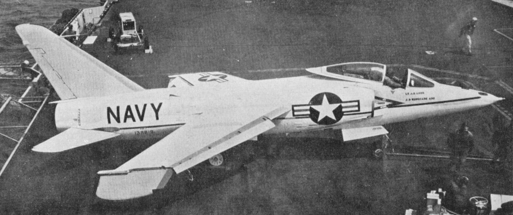
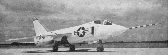
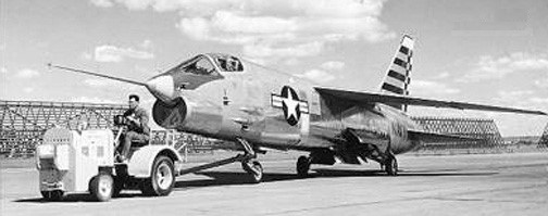
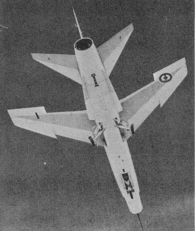
The F8U-3 first flew in early June 1958. It was distinguishable by two retractable ventral fins which improve stability at supersonic speed.

The F8U-1T (TF-8A) was a two-seat version of the original F8U-1. Although it seemed promising during 1962 it never went into full scale production because of US Navy cutbacks. The TF-8A went to Europe to attract customers, the British were at first interested but choose the F-4 Phantom. The TF-8A was sold to NASA and later regained to train Philippine pilots.

The RF-8G was a refurbished RF-8A with a modern engine, strengthened fuselage and wings, ventral fins, new navigation system and cameras. The first RF-8G re-entered service in October of 1965. Lifetime of these unarmed RF-8G photo recce crusader proved to be much longer than anticipated and in 1977 a second upgrade was done. The RF-8G remained in service with the US Navy till 1986 and thereby was the latest and longest serving Crusader in the US Navy.

Vought RF-8G at NAS Alameda, VFP-63

Starting in 1967 the F-8Ds were converted to the F-8H with a new engine. F-8Es were remanufactured as F-8J. The F-8J was the last Crusader fighter to take part in the Vietnam War. The next step was to upgrade the F-8Bs to F-8K and the F-8Cs to F-8L standards. The F-8M was supposed to be the designation for F-8As with low fly time, but there were not enough F-8A.

Crusaders were flown by the navies of France and the Philippines, the French F 8E (FN)s carrying Matra R530 and Sidewinder missiles. The US Navy operated a few modernized RF 8G Crusaders. Power for the F 8E(FN) is provided by one 18,000 lb thrust Pratt & Whitney J57 P 20 turbojet engine, which gives a maximum speed of nearly Mach 2.

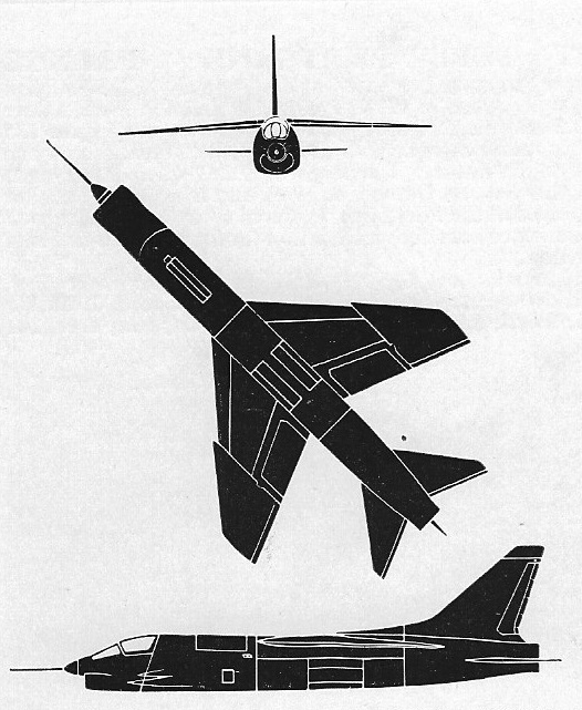
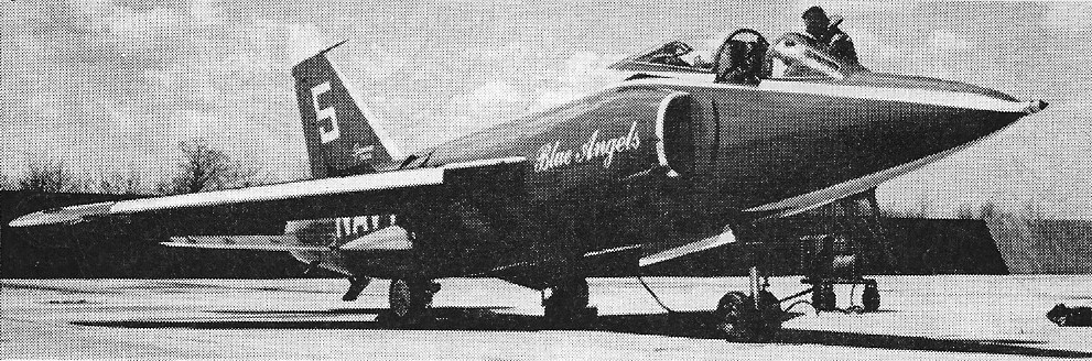
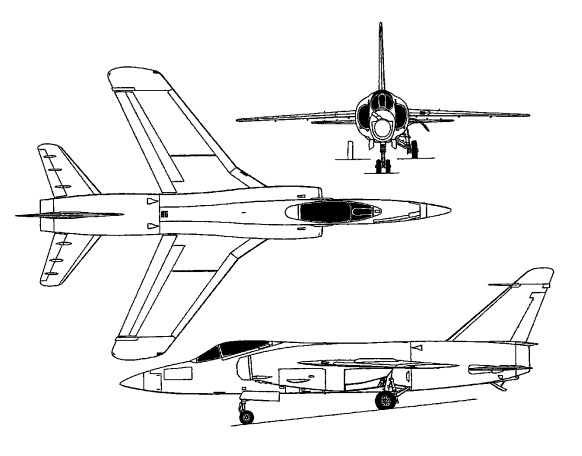
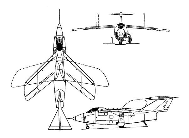
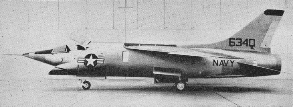
So successful was the Crusader, that a serious effort was made to create a Mach 2 development as the F8U-3 Crusader III. This bore a strong external resemblance to the baseline Crusader, but was virtually a new aeroplane characterized by the revised forward fuselage (with a pointed nosecone and forward-raked ‘sugar scoop inlet) and higher aspect ratio ventral fins that were angled down from the horizontal position for additional stability in supersonic flight. The type first flew on 2 June 1958 but the competing Mcdonnell F4H Phantom II was preferred for production.

Vought XF8U-3 Crusader III 146340

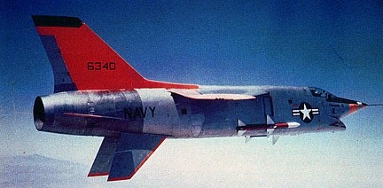
Two F8U-3 Super Crusader, or Crusader III, were built in 1958, 146340 and 146341, powered with 16500 lb P&W J75-P-5A/6 turbojets (29500 lb with afterburners). The maximum speed was never determined, as the canopy would overheat and begin turning opaque at about Mach 2.6. With acceleration still evident at that speed, test pilots felt that Mach 3.0 was attainable.

French service
In 1962 the French Navy (Marine Nationale) ordered the F-8 Crusader to serve as a air superiority fighter aboard the new carrier Clemmenceau and Foch. The F-8 needed more upgrading in order to make it suitable and safe for the smaller French carriers. Improvements such as a bigger maximum angle of incidence for the wing to furthur reduce the landing speed were neccessary. A new weapon system was installed to make it capable for the French R.530 Matra missile. The variant was designated F-8E(FN) and entered service in October 1964. The French Crusader saw multiple upgrade (wings, afterburner and the R.550 Magic missile) until it was finally replaced in December 1999. When the carrier Clemmenceau was sent to the Persian Gulf during the Gulf War the Crusader was tasked with carrier protection against small vessels.

Philippine service
In late 1977, the Philippines government purchased 35 ex-US Navy F-8Hs that had stored at Davis-Monthan AFB in Arizona. 25 of them were refurbished by Vought and the remaining ten were used for spare parts. As part of the deal the US would train Philippine pilots using the TF-8A. In 1988, after having intercepted a large number of Soviet bombers, all were withdrawn from service.

Awarded Collier trophy in 1957 and made the first carrier-to-carrier transcontinental flight, on 6 June 1967, and the first supersonic transcontinental flight, on 16 July 1957.

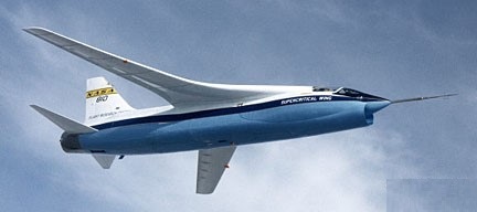
In 1971 NASA modified an F-8 as the F-8SCW to test NASA Langley’s SuperCritical Wing designed by (Richard Whitcomb) to minimize drag from shockwaves that subsequetly represented millions of dollars yearly in fuel savings and reduced air pollution as airlines switched to supercritical-wing aircraft.

Vought F-8SCW

Gallery

Variants:

F8U-1 (F-8A)
Engines: 1 x Pratt & Whitney J57-P-4A, 9,700 lb / 14,000 lb w/afterburn
Wing span: 35 ft 8 in (10.87 m).
Length: 54 ft 3 in (16.54 m).
Height: 15 ft 9 in (4.8 m).
Wing area: 350 sq.ft
Wheel track: 9 ft 8 in
Empty weight: 16,500 lb
Max TO wt: 34,000 lb (15,420 kg)
Max speed: 940 mph SL / 820 mph 36,000 ft
ROC: 15,000 fpm
Ceiling: 54,000 ft
Armament: 4 x 20 mm cannon

F8U-1P (RF-8A)

F8U-1T (TF-8A)

F8U-1E (F-8B)

F8U-2 (F-8C)
Engine: P&W J57-P-16/-20, 10700 lb (16900 lb with afterburner)
Wingspan: 35’8″
Length: 54’3″
Max speed: 1120 mph
Cruise: 560 mph
Range: 1400 mi
Ceiling: 59.000′

F8U-2N (F-8D)
Engine: P&W J57-P-16/-20, 10700 lb (16900 lb with afterburner)
Wingspan: 35’8″
Length: 54’3″
Max speed: 1120 mph
Cruise: 560 mph
Range: 1400 mi
Ceiling: 59.000′

F8U-2NE (F-8E)
Engine: P&W J57-P-16/-20, 10700 lb (16900 lb with afterburner)
Wingspan: 35’8″
Length: 54’3″
Max speed: 1120 mph
Cruise: 560 mph
Range: 1400 mi
Ceiling: 59.000′

F8U-3 Crusader III
Engine: P&W J75-P-5A/6, 16500 lb (29500 lb with afterburners)
Wingspan: 38’11”
Length: 58’9″
Max speed SL: 800 mph (1457 mph at 50,000′)
Cruise: 575 mph
Stall: 154 mph
Range: 645 mi
Ceiling: 51,000′

RF-8G

F-8H
1968 F-8D modified to include external wing ordnance, increased strength fuselage, lead-launch computer, other improvements.

F-8J
F-8E with larger fuselage, wings, other improvements.
Engine: P&W J57-P-16/-20, 10700 lb (16900 lb with afterburner)
Wingspan: 35’8″
Length: 54’3″
Max speed: 1120 mph
Cruise: 560 mph
Range: 1400 mi
Ceiling: 59.000′

F-8K
F-8C with structural changes to fuselage, wing, landing gear.

F-8L
F-8B with structural changes to fuselage, wing, landing gear.

F-8M
F-8A with structural changes to fuselage, wing, landing gear.

F-8E(FN)
Engine: one 80 kN (19,000 lb st) Pratt & Whitney J57-P-20A afterburning turbojet
Length: 16.61m (54 ft 6 in)
Height: 4.80m (15 ft 9 in)
Wing span: 10.72m (35ft 2 in)
Take-off (’empty, equipped’) weight: 8.935 kg (19,700 lb)
Max Take-Off Weight: 15.420 kg (34,000 lb)
Max level speed: Mach 1.7+ / 1.827+ km/h (1,135+ mph)
Service ceiling: 17,680m (58,000 ft)
Armament: 4x 20mm Colt Mk 12 cannons / 84 or 144 rds each

Grumman C-1 Trader

C-1A

Requiring a transport able to support aircraft carriers at sea with high-priority freight and personnel, the US Navy contracted with Grumman for a derivative of its S2F (later S-2) Tracker carrierborne anti-submarine plane for the COD (Carrier Onboard Delivery) role in succession to considerably more limited types such as the 12-passenger version of the Douglas AD-5 Skyraider. The G-96 design was based closely on the S2F with its fuselage remodelled for the transport role, and as such was fully compatible with 52F support equipment on board American carriers. The type appeared in 1955 as the TF-l Trader, and 87 aircraft were produced. In 1962 these were redesignated C-lA, and the machines were eventually supplemented and finally supplanted by the same company’s C-2A Greyhound.

Grumman C-1 Trader Article

Principal versions -TF-l (COD plane later redesignated C-1A) and TF-1Q (four aircraft modified for electronic countermeasures training, later redesignated EC-1A). Generally one C-lA Trader was permanently attached to each American carrier, and others were allocated at strategically placed naval air stations to support carriers operating round the USA, Europe, and the Far East.
The C 1A is run with a three man crew. All seats in the cabin face the rear, and the accommodations are far from plush. Double strap shoulder harnesses are standard. The C 1A is a relatively slow airplane indicating 150 knot cruise. The C 1A can make a deck run takeoff, but the catapult is preferable, because after a deck run the airplane goes off the end below its engine out minimum control speed. The C-1A leaves the cat at 112 knots, the best single engine rate of climb speed with one third flaps.

C-lA Trader
Two/three-crew carrier onboard delivery plane.
Engines: 2 x 1,525-hp (1,137-kW) Wright R-l820-82 Cyclone radial.
Maximum speed 290 mph (467 km/h) at 4,500 ft (1,370 m)
Initial climb rate about 1,800 ft (549 m) per minute
Service ceiling 22,000 ft (6,705 m)
Range about 800 miles (1,288 km)
MTOW: 27,000 lb (12,247 kg).
Wing span 72 ft 7 in (22.12 m)
Length 43 ft 6 in (13.26 m)
Height 16 ft 7 in (5.05 m)
Wing area 499.0 sq ft (46.36 sq.m).
Payload: nine passengers or freight.

E-1B Tracer –

Grumman G-98 F11F Tiger / F-11

The US Navy’s first transonic shipboard warplane, development of the G-98 was ordered on 27 April 1953 as a revised and improved F9F-6. In the event, there was no commonality with the earlier fighter, but nevertheless, when the first example was flown on 30 July 1954, it was designated YF9F-9, this being changed to F11F-1 in April 1955.

Grumman F11F Tiger Article

The airframe had mid-set wings sweptback at 30 degrees. There are swept-back tail surfaces, with an all-moving tailplane mid-set on the fuselage. No ailerons are fitted. Lateral control being by spoilers. Leading edge slats are fitted. Trailing-edge flaps are over the full span except for the folding tip portions. Finger type air-brakes are under the fuselage. Two underwing jettisonable fuel tanks may be fitted.

The tricycle under-carriage has a single wheel on each main unit and twin-wheel nose unit. The main wheels retract forward and into the fuselage, and the nose wheels retract rearward.

Able to fly supersonic in level flight, the F11F-9 Tiger was in production for the U.S. Navy in 1955. Six prototypes and 39 F9F-9 were ordered initially. Difficulties with the intended afterburning Wright J65-W-6 engine dictated installation of the derated J65-W-18 in the production F11F-1 with a maximum military thrust of 7,450 lb (3379 kg) and 10,500 lb (4 763 kg) with full reheat. In consequence, the F11F-1 failed to meet contractual performance guarantees.

F11F-1 Tiger

A small number of pre-production aircraft, each with a Wright J65-W-6 turbojet engine with afterburner, were followed by 39 production aircraft (ordered with J65-W-4 afterburning engines).

Grumman F11F-1

The last two Tigers of the initial production batch were fitted with the General Electric YJ79-GE-7 turbojet rated at 9,600 lb (4 355 kg) military thrust and 15,000 lb (6 804 kg) with reheat as F11F-1Fs.
One of the F11F-1Fs attained a speed of 1,963km/h and set a short-lived height record on 18 April 1958 of 23,449m.

A further contract for J65-W-18-engined Tigers placed for the US Navy brought the total number of F11F-1s built to 201, but these were gradually phased out of first-line service from 1959. Those which remained in second-line service when the tri-service designations became rationalised in 1962 were redesignated F-11A.

F-11A Tigers of Blue Angels 1965

Production was limited to 201 aeroplanes, the last being delivered in March 1957, service phase-out commencing in 1959.

F11F-9 Tiger

Gallery

F11F-1
Engine: 1 x Wright J-65-W-6, 33.8kN
Max speed, 753 mph (1212 km/h) at sea level.
Initial climb, 16,300 ft/min (82,8 m/sec).
Range, 1,108 mls (1783 km).
Service ceiling: 16700 m / 54800 ft
Empty weight, 13,307 lb (6 036 kg).
Max loaded weight, 23,459 lb (10 641 kg).
Span, 31 ft 8 in (9,65 m).
Length, 44 ft 10.75 in (13,68 m).
Height, 13 ft 2.75 in (4,03 m).
Wing area, 250 sq ft (23,22 sq.m).
Armament: four 20-mm cannon.
Crew: 1

F11F-1
Engine: 1 x Wright J-65-W-18, 10,500 lb
Span, 31 ft 8 in (9,65 m).
Wing area, 250 sq ft (23,22 sq.m).
Length, 44 ft 10.75 in (13,68 m).
Height, 13 ft 2.75 in (4,03 m).
Empty weight, 13,307 lb (6 036 kg).
Max loaded weight, 24,078 lb
Max speed, 740 mph / M1.12 at 35,000 ft
Service ceiling: 50,500 ft
Range, 600 mls
Armament: four 20-mm cannon.
Hardpoints: 4
Crew: 1

F11F-9 Tiger
Naval fighter
Crew: 1
Engine: Wright J65-W-7 Sapphire turbojet, with afterburner, 7500 lb. thrust.
Wingspan: 31 ft. 5 in
Length: 39 ft.
Loaded weight: approx. 14,000 lb.

Grumman G-93 F9F Panther / Cougar / G-99

F9F Cougar

The first jet-powered ‘cat’ to be produced by Grumman and the first carrier borne jet to get into combat, the F9F Panther performed Korea where it constituted the backbone of US Navy and US Marine Corps air power, and by the time production ceased in late 1952 close to 1,400 had been built.

The Cougar was a swept-wing development of the earlier G-79 Panther. The fuselage was similar but the wings and tailplane were swept at 35 deg. The original layout of this single-seat carrier-based fighter provided for the installation of four wing-mounted Westinghouse 19XB-2B (Navy J30) axial-flow jets. But this arrangement was abandoned in favour of one fuselage-mounted high-powered turbojet engine before prototype construction began, a change prompted by the successful tests conducted by the Navy in December 1946 with two imported Rolls-Royce Nene engines. Grumman then turned its attentions to a single-seat single engine jet day fighter, two prototypes duly being ordered with the designation XF9F-2. Powered by an imported Rolls-Royce Nene engine, the first of these made its maiden flight on 24 November 1947 and such was the promise shown that substantial orders were soon forth¬coming for production-configured F9F-2 aircraft fitted with the licence-built Pratt & Whitney J42 copy of the Nene turbojet and British made Stanley Model 22G ejection seat.

The second prototype was similarly fitted, but the third (the XF9F-3) had an Allison J33 engine. Production aircraft were divided between Nene and Allison-powered models, the former engines licence-built by Pratt & Whitney as J42s.

The first production F9F-2, powered by a 22.24kN J42-P-6, flew for the first time on 24 November 1948. The 20.46kN J33-A-8-powered prototype flew for the first time on 15 August 1948 and a total of 418 of both versions were built. However the F9F-2 proved to be the better version and the F9F-3s were re-engined to F9F-2 standard.

Although the F9F-2 was the initial production model, the honour of being the first variant to enter service fell to the F9F-3, which used the slightly less powerful Allison J33 engine. This joined US Navy Fighter Squadron VF-51 during May 1949 but in the event only 54 F9F-3s were completed, most being modified later to F9F-2 standard. The next version to appear was the F9F-4 (73 of which were ordered originally) with the Allison J33-A-16, but none was completed and the contracts were combined with those for more than 580 27.80kN Pratt & Whitney J48-P-4/6A-engined F9F-5s (which flew for the first time on 21 December 1949). The F9F-2, -3, -4 and -5 were in service in 1955.

The most prolific variant was the F9F-5 which was powered by the Pratt & Whitney J48, a licence-built Rolls-Royce Tay, and redesigned fin and rudder. Over 600 were completed by the time production ceased at the end of 1952, this total including a small number of F9F-5P aircraft for photo reconnaissance duties. F9F-5P is long-nosed photo-reconnaissance version. Later machines can be seen with flight refuelling nose-probe.

F9F-5 Panther

The F9F-5 was the last version to see squadron service, being finally retired by VAH-7 in October 1958, although many Panthers continued to fly after that date with training units, and as F9F-5KD (from 1962 DF-9E) drone targets and controllers for missile trials.
The F9F-4 was powered by an Allison J33-A-16 engine. The F9F-5P was a photographic-reconnaissance version with a longer camera nose.

First flown in prototype form as the XF9F-6 on 20 September 1951, the Grumman F9F Cougar evolved from the earlier F9F Panther series of fighter aircraft. It differed mainly from its predecessors by virtue of posses¬sing swept wings and tailplane, thus earning the distinction of being the first swept-wing carrierborne type to enter service. Apart from this, changes were kept to a minimum to facilitate rapid production. Indeed, the new Cougar entered service just 14 months after its maiden flight took place, initial exam¬ples of the 32.25kN Pratt & Whitney J48-P-8-engined F9F-6 (later designated F-9F) joining VF-32 of the Atlantic Fleet naval air force during November 1951.

F9F-5 Cougar

Shortly after this, deliveries to Pacific Fleet units got under way, and the type was very soon introduced to combat in Korea. Production of the F9F-6 totalled 706 aircraft, 60 of which were completed as unarmed F9F-6P machines for reconnaiss¬ance duties with a longer nose to accommodate K-17 and tri-metrogon cameras, and these were followed by the F9F-7 (F-9H) which was pow¬ered by an Allison J33-A-16A turbojet. This proved to be only a temporary change, and after completing 168 F9F-7s Grum¬man reverted to the Pratt & Whitney J48 engine for the F9F-8 (which bore the Grumman design designation G-99) (F-9J), which became the definitive Cougar, well over 1,000 being completed in three basic variants. First to appear was the F9F-8 (601 built). Movable leading-edge slats were replaced by fixed cambered leading-edge extensions outboard of the wing fences. Total internal fuel capacity was increased by 530 litres. Large numbers were later modified to F9F-8B (AF-9J) standard with provision for air-to-surface guided missiles. The first production F9F-8 flew on 18 January 1954.

Grumman F9F Cougar / Panther Article

Some 110 of a photo-reconnaissance version designated F9F-8P (RF-9J) flew for the first time on 21 August 1955 and had an extended nose for the cameras.

F9F-5P

The Cougar also lent itself to the training of future naval aviators; a prototype two-seat YF9F-8T first flown on 4 April 1956 was followed by 399 F9F-8T (TF-9J) production examples, some of which remained in use with Naval Air Training Command until well into the 1970s. The F8F-8T was armed with two 20mm cannon and was 23 inch longer than the original cougar. Production of this version ended on the last day of 1959.

As far as front-line units were concerned, the Cougar disappeared from the scene early in 1960, the last operational version being the F9F-8P, but many continued to fly long after that date with the Reserve Force and with Air Training Command. Surplus aircraft became F9F-6K (QF-9F) and F9F-6K2 (QF-9G) target drones or F9F-6D (DF-9F) drone directors.

F9F-8T Cougar

Panthers are remembered for recording a victory against an enemy jet aircraft, a MiG-15, on 9 November 1950.

Replica: Gros F9F Panther

Gallery

F9F-5 Panther
Engine: one 3175-kg (7,000-lb) thrust Pratt & Whitney 148-P-6A turbojet
Maximum speed 932 km/h (579 mph) at 1525 m (5,000 ft)
Cruise speed: 774 km/h / 481 mph
Service ceiling 13380 m (43,900 ft)
Range 2092 km (1,300 miles)
Empty weight 4603 kg (10,147 lb)
Maximum take-off 8492 kg (18,721 lb)
Wingspan 11.58 m (38 ft 0 in)
Length 11.58 m(38 ft 0 in)
Height 3.73 m (12 ft 3 in)
Wing area 23.23 sq.m (250 sq ft).
Armament: four 20-mm cannon, plus up to 1361 kg (3,000 lb) of external ordnance.
Crew: 1

F9F-5 Cougar
Naval fighter
Engine: Pratt & Whitney J48-P-8 turbojet with afterburner, 7200 lb. thrust
Wingspan: 36 ft. 5 in
Length: 42 ft. 3 in
Loaded weight: approx. 20,000 lb.
Max. speed: 690 m.p.h.
Ceiling. 50,000 ft.
Range: approx. 1,000 miles.
Crew: 1
Armament: 4×20 mm. Cannon

F9F-5P
Naval photo-reconnaissance aircraft
Engine: Pratt & Whitney 148-P-6A turbojet, 6,250 lb. thrust
Wingspan: 38 ft
Max. speed: 625 m.p.h.
Loaded weight: 15,750 lb.
Ceiling: over 50,000 ft.
Max. range: 1,200 miles.
Crew: 1.
Armament: None

F9F-6
Engine: Pratt & Whitney J48-P-6A, 6,250 lb (2 835 kg).

F9F-7
Engine: Allison J33-A-16, 6,250 lb (2 835 kg).

F9F-8 Cougar
Engine: one 3289-kg (7, 250-lb) thrust Pratt & Whitney J48-P-8A turbojet.
Maximum speed 1033 km/h (642 mph) at sea level
Service ceiling 12800 m (42,000 ft)
Range 1690 km(l,050 miles)
Empty weight 5382 kg (11,866 lb)
Maximum take-off 11232 kg (24,763 lb)
Wingspan 10.52 m (34 ft 6 in)
Length 12.73 m(41 ft 9 in)
Height 3.72 m (12 ft 2.5 in)
Wing area 31.31 sq.m (337 sq.ft).
Armament: four 20-mm cannon, plus up to 1814 kg (4,000 lb) external ordnance

F9F-8P

TF-9J
Engine: 1 x Pratt & Whitney J48-P-8A turbojet, 32.0kN
Max take-off weight: 9344 kg / 20600 lb
Wingspan: 10.52 m / 34 ft 6 in
Length: 13.54 m / 44 ft 5 in
Height: 3.73 m / 12 ft 3 in
Service ceiling: 15240 m / 50000 ft
Range: 966 km / 600 miles
Armament: 2 x 20mm cannon, 907kg external

Grumman F9F Panther
Grumman F9F Cougar

Grumman G-83 / XF10F Jaguar

Greater success attended the development of variable-geometry wings, which allow the use of a minimum-sweep position for take-off and landing, an intermediate-sweep position for fuel-economical cruise, and a maximum-sweep position for high dash performance. The navy’s first essay in this field was the Grumman XF10F Jaguar, which was conceived in 1948 as a possible successor to the F9F Panther. The aerodynamic features of a variable-geometry type had already been explored in a number of aircraft, most notably the Westland Pterodactyl IV developed in the UK during the early 1930s, the Messerschmitt P.1011 designed in Germany during World War II, and the experimental Bell X-5 sponsored by NACA and the LTSAF with the ultimate purpose of validating a fighter-type wing with sweep variable between 20 deg and 60 deg. The X-5 had not flown when Grumman set to work on the Jaguar, but a considerable quantity of engineering data was available and this proved valuable to the Grumman engineers, who were faced with a host of problems.
Originally the XF10F had been planned as a development of the Panther with clipped delta flying surfaces. Designed as a transonic single-seat shipboard fighter with an internal armament of four 20-mm cannon and provision for an external bomb load of up to 4,000 lb (1814 kg). The sweep angle of the wings could be varied hydraulically between 13.5 and 42.5 deg, and high-lift devices consisted of full-span slats and an 80 per cent Fowler flap. The concept was then refined to the point at which a tilting variable-incidence wing was in adopted for reduction of the take-off and landing speeds. The navy then added additional responsibilities to the basic fighter-role, and these so increased the structure weight that the company came up with the notion of providing a variable-geometry wing. Further refinement was added after this when it was decided to allow the wing to be swept at any angle between the minimum- and maximum-sweep angles. The provision of such wings increased the type’s weight by 2200 lb (998 kg) but reduced landing speed from 132.5 mph (213 km/h) to 109 mph (175 km/h). The Jaguar was also provided with an advanced control system that included a delta surface forward of the fin to act as a servo for the all-moving tailplane and so improve control response at transonic speed.
The tailplane was operated by a novel arrangement where the pilot controlled a small delta-wing airfoil at the tip of the tail bullet. This in turn moved the main elevator Unfortunately, a lag in the response between stick and surface usually resulted in a Pilot Induced Oscillation (PIO) and the Jaguar was virtually uncontrollable much of the time.

The engineering of so complex an aeroplane took considerably longer than expected, and it was May 1953 before the XF10F prototype flew, three years behind schedule. The Jaguar was intended to be powered by a Westinghouse XJ40-WE-8 turbojet rated at 7,400 lb (3 357 kg) military thrust and 10,900 lb (4 944 kg) with full reheat, but when flight trials were initiated on 19 May 1952, a J40-WE-6 rated at 6,800 lb (3 084 kg) was fitted. The novel servo-control system for the tailplane proved far too slow in operation, and was replaced by a conventional powered tailplane, but it soon became clear that considerable revision of the basic design would have to be undertaken before production aircraft could be considered. Numerous problems arose during the test programme and as some of these could not be resolved, trials terminated with the 32nd flight on 25 April 1953. Orders had been placed for 112 production F10F-1s, but 100 of these were cancelled on 1 April 1953 and the remaining 12 on the following 12 June.

Empty weight, 20,426 lb (9 265kg).
Max loaded weight, 35,450 lb (16080 kg).
Span (min sweep), 50 ft 7 in (15,42 m), (max sweep), 36 ft 8 in (11, 17 m).
Length, 54 ft 5 in (16,59 m).
Height, 16 ft 3 in (4,95 m).
Wing area (min sweep), 467 sq ft (43,38sq.m), (max sweep), 450 sq ft (41,81sq.m).
Max. speed: 1143 km/h / 710 mph
Range: 2687 km / 1670 miles

Gloster GA.5 Javelin

Javelin FAW Mk.1

Designed to meet the requirements of Specification F.4/48 for a two-seat twin-engined all-weather interceptor fighter, the Javelin was of tailed-delta configuration and the first of seven prototypes was flown on 26 November 1951. The Javelin suffered a protracted development period, being subjected to delays arising from poor handling qualities and difficulties with integration of the radar.

The third prototype, WT827, had a straight wing and early cockpit canopy. WT830, the fourth prototype, had a revised “cranked” leading edge giving a better fineness ratio over the ailerons, and also the old cockpit and no guns; and WT 836, the fifth prototype, which is to full production standard. This has a more extensive transparency over the rear cockpit with a streamlined fairing behind instead of the former rather abrupt cut off to the canopy. The fifth prototype also had the standard “cranked” wing and the full armament of four 30 mm cannon mounted just outboard of the angle in the leading edge.

Gloster GA.5 Javelin Article

It was not until late 22 July 1954 that the first production specimen made its maiden flight. This was the Javelin FAW.Mk 1, powered by two 3629kg Armstrong Siddeley Sapphire ASSa 6 turbojets and carrying an armament of four 30mm Aden cannon, which began to enter service with No. 46 Squadron in February 1956.

Forty F(AW) Mk Is for the RAF were followed by 30 F(AW) Mk 2s, the first example of this version flying on 31 October 1955.

The FAW.1 was su¬perseded in production by the Javelin FAW.Mk 2 which featured American (APQ 43) interception radar in place of the Brit¬ish (AI17) equipment originally fitted. Both of these models were armed with four 30-mm Aden cannon, as was the Javelin FAW.Mk 4 which intro¬duced an all-moving tailplane in an attempt to eliminate excessive stick force requirements when flying at high indicated speeds. First flown on 19 September 1955, differed in having a fully-powered all-moving tailplane, 50 being built.

The F(AW) Mk 4 paralleled production of 21 T Mk 3 dual-control trainers.

Additional fuel capacity in the wings and having provision for four de Havilland Firestreak AAMs was introduced in the Javelin FAW.Mk 5, which was otherwise virtually identical to the Javelin FAW.Mk 4, and both of these variants duly entered service during 1957. Sixty-four F(AW) Mk 5 were built.

The final ‘first-generation’ model was the Javelin FAW.Mk 6, which was basically a Javelin FAW.Mk 5 fitted with American radar. 33 F(AW) Mk 6s were built.

Whilst production of these was progressing, a major redesign effort had been initiated with the objective of installing the rather more powerful 4990kg Sapphire ASSa 7 200 series engine, and the first model to appear with this power-plant was the Javelin FAW.Mk 7, which also incorporated increased fuel capacity, Firestreak infra-red homing missiles modified flying controls, an extended rear fuselage with raised topline, and later interception equipment, though this entailed the loss of two Aden cannon. Armament comprised two 30mm Aden cannon and four Firestreak AAMs, and 142 were built. The Javelin FAW.Mk 7 took to the air for the first time in November 1956, deliveries get¬ting under way in August 1958.

The FAW.7 model was succeeded by the Javelin FAW.Mk 8 with US radar, drooped wing leading edges and a Sapphire ASSa 7R engines with limited afterburning boosting output to 5579kg above 6100m. Entering service with No. 41 Squadron during early 1960, the Javelin FAW.Mk 8 was the last new-build Javelin variant to appear. Forty-seven were built during 1957-60.

Production of the type terminating on 16 August 1960 when the 381st example made its initial flight.

Subsequently 76 Javelin FAW.Mk 7s were updated to the definitive Javelin FAW.Mk 8 configuration, though retaining British radar, as Javelin FAW.Mk 9 aircraft standard during 1960-61, with Armstrong Siddeley Sapphire Sa.7R after-burning engines. It had a maximum speed of 702 mph and a service ceiling of 52000 feet. Armament was four Firestreak air-to-air missiles and two 30 mm Aden guns.

Javelin F.(A/W.) Mk.9

The Mk.9 having 28.5 degrees sweepback on the inner wings and 33.8 degrees on the outer section. Split flaps are under the wings and slotted-plate airbrakes above and below the wings, near the trailing edge, aft of the flaps.

The tricycle undercarriage has a single wheel on each unit. The mains retract inward into the wings and the nose wheel retracts rearward. They can have a flight-refuelling boom from the right side of the cockpit area.

Fuel tanks are in the wings and fuselage and can be supplemented by two 259 Imp.Gal tanks flush under the fuselage and up to four underwing tanks.

Late marks of Javelin were modified circa 1960 to accommodate aerial-refuelling equipment.

Javelin FAW.8 refuelling from a Vickers Valiant

The Javelin was finally withdrawn from RAF service in 1967.

Gallery

Javelin F(AW). Mk 1
Engnes: 2 x Armstrong Siddeley Saphire ASSa.6 turbojets, 35.6kN
Max take-off weight: 14324 kg / 31579 lb
Wingspan: 15.85 m / 52 ft 0 in
Length: 17.15 m / 56 ft 3 in
Height: 4.88 m / 16 ft 0 in
Wing area: 86.12 sq.m / 926.99 sq ft
Max. speed: 1141 km/h / 709 mph
Ceiling: 16000 m / 52500 ft
Crew: 2

FAW Mk.8
Engines: two 5548-kg (12,230-lb) afterburning thrust Bristol Siddeley Sapphire Mk 203/204 turbojets.
Maximum speed 1101 km/h (684 mph) at sea level
Iinitial climb rate 3734 m (12,250 ft) per minute
Service ceiling 15645 m (51,330 ft)
Rnge with two 1137-litre (250-Imp gal) drop tanks 1497 km. (930 miles).
Mximum take-off weight (40,000 lb).
Wing span 15.85 m (52 ft 0 in)
Legth 17.16 m (56 ft 3.5n)
Hight 4.88 m (16 ft 0 in)
Wing area 86.12 s (927 sq ft).
Armament: two 30-mm Aden cannon, plus four Firestreak air-to-air missiles

Javelin F.(A/W.) Mk.9
Engines: 2 x Bristol Siddeley Sapphire 203/204, 12,300 lb with reheat
Wingspan: 52 ft
Wingarea: 928 sq.ft
Length: 56 ft 4 in
Height: 16 ft
Wheel track: 23 ft 4 in
Armament: 2 x 30 mm Aden cannon

English Electric TSR.2 / BAC TSR-2

English Electric TSR-2 Mach 2 tactical strike and reconnaissance aeroplane, evolved from the P.17A concept.
The TSR-2 remains the classic example of technical and operational promise ultimately stultified by economic worries and finally denied by political prejudice. It resulted from a May 1957 Royal Air Force requirement for a tactical strike and reconnaissance aeroplane to replace the English Electric Canberra, which would be able to operate at very low levels at supersonic speed, deliver heavy weapon loads over long ranges with very high accuracy, and operate from short runways through the provision of STOL capability.

The two most promising contenders were those from Vickers and from English Electric in collaboration with Shorts. The RAF opted for a combination of features from the two designs, and the government virtually forced English Electric and Vickers to merge as the British Aircraft Corporation, which also incorporated Bristol Aircraft. The development of the new aeroplane pushed forward the technologies of the time quite considerably in a number of fields, and inevitably involved a number of companies other than BAC (overall responsibility and airframe) and Bristol Siddeley (powerplant). Other major contributors were Elliott Automation for the integrated automatic flight control and inertial navigation systems, Ferranti for the terrain-following radar and nav/attack system, EMI for the side-looking radar used for reconnaissance and additional navigation input in long-range flights, and Marconi for the avionics.

The design was frozen in 1962 and construction of the prototypes began. There were many problems to be overcome, but the promise was a warplane more advanced than any in service or under development anywhere in the world at that time. Pitch and roll control was entrusted to the all-moving tailplane working collectively or differentially, and this allowed the entire trailing edge of the wings to be used for the blown flaps that contributed signally to the TSR-2’s STOL capability. The nav/attack system was extremely advanced, and in combination with the automatic flight control system permitted supersonic terrain-following flight at heights down to 200 ft (61 m).

English Electric TSR-2 Article

The Bristol Siddeley Olympus development became the pacing factor for the project, falling behind schedule and continually plagued with problems. Even when the TSR2 eventually got airborne for the first time, it did so with strictly non airworthy engines, which had to be operated at reduced power.

Eventually the first prototype, XR219, became airborne for its maiden flight on 27th September 1964, six and a half years after the original requirement was raised. In the event, it was to be the only prototype to fly. The second one, XR220, fell off the back of a lorry on delivery to Boscombe Down, and it says much for the strength of the airframe that the subsequent rigging checks revealed nothing out of alignment. It was just ready for flight when cancellation came. It carried one of the few noticeable external differences, this being the fitting of camera fairings to each side of the engine intakes, to photograph underwing stores separation tests. The third machine, XR221, was intended to be the full electronics test aircraft, and was under¬going trials at Weybridge prior to flight. The fourth, XR222, was also virtually complete.

All the flying was done by XR219, lasting barely six months, and totalling only 24 flights.

In the first Budget Speech by the newly elected Labour Government in 1965, the cancellation of the whole programme was announced. Not only was it to be cancelled, but to ensure that the project could never be resurrected, all jigs, production drawings and completed components were to be totally destroyed. A proposal was made that XR219 should be kept flying for pure research purposes, but this was also rejected, and the contract was officially terminated on 6th July 1965, in favour of the General Dynamics F-111. The F-111 programme then suffered a number of severe problems and escalating costs, and the British order was cancelled.

At cancellation, in addition to the three com¬pleted aircraft, there were 17 others on the production line, as well as major com¬ponents for several others, with long lead items for a total of a further 50 aircraft.
The first prototype was sent to Shoeburyness to act as a gunnery target to assess damage to modern air-frames. XR220 was allocated to the Royal Air Force Museum and XR222, after a spell at Cranfield, to Duxford as a part of the Imperial War Museum’s collection.

Gallery

Engines: two Bristol Siddeley Olympus Mk 320 turbojets, 30,610 lb (13,885-kg) afterburning thrust
Wingspan 37 ft (11.28 m)
Length 89 ft (27.13 m)
Height 24 ft (7.32 m)
Wing area 700 sq.ft (65,03 sq.m)
Maximum speed at high altitude 1360 mph (2185 km/h) or Mach 2.05
Maximum speed at sea level 840 mph (1352 km/h) or Mach 1.27.
Empty weight 44,850 lb (20,344 kg)
Maximum take-off weight: 95,500 lb (34,500 kg).
Ceiling: 16500 m / 54150 ft
Range w/max.fuel: 6840 km / 4250 miles
Range w/max.payload: 1280-1850 km / 795 – 1150 miles
Operational radius 1,152 miles (1853 km) with 2000lb (907-kg) internal warload
Crew: 2
Armament: internal 6000-lb (2724-kg, 4 x underwing hardpoints max 6000 lb (2722 kg)

English Electric P.1 Lightning

Lightning T.5

As chief engineer of English Electric’s Aircraft Division it was W.E.W.(Teddy) Petter’s responsibility to keep looking at new projects. Towards the end of 1946 he spent some time sketching possible configurations for a supersonic aeroplane. It was characterised by sharply swept wings and tailplane and a long slab sided body with two engines one above the other.
He had discussions with officials at the Ministry of Supply early in 1947, and was rewarded in May of that year by a study contract for an aircraft to meet a supersonic specification, ER.103 (ER= experimental research). The officials suggested Mach 1.5, equivalent at 36,000ft to about 860 kt.
The Air Staff agreed to write a specification for an aeroplane “to investigate the practicality of supersonic speed for military aircraft”, designed to have fighter like handling characteristics, to be built to fighter strength factors (7g) and to carry guns and a sighting system.

English Electric P.1 Lightning Article

The specification was F.23/49. It was not put out to general tender; instead English Electric were awarded a contract for two flight prototypes and a static test airframe. They called the aircraft the P.1 (project 1). It followed Petter’s long earlier refinement of the classic configuration he had conceived, with the single notable change that he put the tailplane very low on the rear fuselage instead of on top of the fin.
He chose to use a pair of simple Armstrong Siddeley Sapphire turbojets, with plain fixed nozzles and no reheat, and fed by a plain inlet in the nose. This was in keeping with his “simple, off the shelf” philosophy. To minimise frontal area he staggered the engines, bringing the lower one well forward with a long jet pipe. After a lot of study he adhered to his original plan to have a mid wing, with the engine air ducts passing above and below it. The form of the wing was crucial, and unique, notable features being the fact that the 60O sweep halved the apparent ratio of thickness to chord and allowed it to have a generous radius on the leading edge, and the ailerons joined the leading and trailing edges in a novel way.
Petter left the body free of fuel and marked out part of the main torsion box of the wing to serve as an integral tank. He devoted a large bay to the rear of the torsion box to house the main gears in an unusual installation with doors hinged on the inboard side of the wheel well, even though the legs retracted outwards. The legs had to be long, because it was clear that the P.1 would take off and land at a marked nose up angle. Owing to the thin wing the wheels had to be of large diameter and have tyres inflated to high pressure (no less than 2801b/sq in). To minimise drag the canopy was made flush with the top of the fuselage, though a flat windscreen was provided for the gunsight. The nosewheel folded forwards and turned to lie flat under the inlet duct. All controls were fully powered, the horizontal tail being of the new “slab” type, and there were sharply swept split flaps. Petter was careful not only to stress the P.1 for 7g but also to make weight provision for a military payload.
So advanced was the design – and so complex the aerodynamic problems which this design posed – that Britain’s first transonic wind tunnel was built to facilitate testing. Short Brothers at Belfast were instructed by the Ministry of Supply (MoS) to build a research aircraft able to investigate aspects of Petter’s design which the MoS considered more revolutionary than functional. Thus Short’s S.B.5 had a wing which could investigate sweepback at 50 degrees, 60degrees and 69degrees, landing gear which could be adjusted to cater for the CG changes in these different configurations and, at a later stage, a low-set tailplane. When both wind tunnel testing and S.B.5 confirmed that Petter’s design had been right from the outset, the MoS let English Electric get on with construction of two prototypes and a static test airframe.

Pilot – Wg.Cdr. R.P.Beaumont

English Electric P1A, WG760, was the first of two prototypes and had its maiden flight on 4 August 1954, piloted by Roland Beamont. On its third flight the aircraft became the first British aircraft to exceed Mach 1 in level flight. On his third flight the Mach needle refused to move beyond 0.98, but subsequent analysis suggested the P.1 had gone supersonic. Later this machine, WG760, and its partner, WG763 (which had guns, and first flew on July 18, 1955), explored the flight envelope to mach 1.53, demonstrated superb handling qualities and were later given a bigger fin to ensure ample stability margins at high Mach numbers, and a neat faired in belly tank to increase the fuel capacity above the original limit of a mere 5,000lb. The first aircraft flew with Sapphires with crude reheat and fixed area nozzles sized to the reheat condition.

P.1B

The second flew with a revised wing with a kinked leading edge and broad tips with inset ailerons which gave better low speed lift and longer range, as well as opening out the high altitude buffet boundary.

In 1953 a standard of build was agreed for an operational fighter designated P.1B. It was to carry the Ferranti AI 23 radar in the pressurized conical centrebody of a redesigned inclined shock intake with a centrally mounted shock cone, and have a removable armament pack carrying two Blue Jay (Firestreak Mk 1) guided weapons on external pylons, plus their associated electronics and interface systems, or as an optional alternative, two 30mm Aden guns and ammunition. A third alternative was two retractable boxes, each housing 24 FFARs (foldingfin aircraft rockets). After a lot of argument it was also agreed to fit a 30mm Aden gun on each side of the cockpit in a permanent installation. The engines were changed to Rolls-Royce Avon 201s, with four stage reheat, the flaps were made of the plain type (and later used as integral tanks), the fuselage was redesigned with a raised clear vision canopy and many other changes (such as new air¬brakes and dozens of access panels to the profusion of added equipment items), the nose gear was redesigned to fold into the “6 o’clock” inlet strut, and there were countless less obvious changes such as an air bleed turbo¬alternator. The kinked/cambered wing was not incorporated, neither was a refuelling probe.
The first of the three hand-built P.1B prototypes first flew on 4 April 1957 with the more powerful engines mounted one above the other in the rear fuselage, with the lower engine well forward of the upper.
The production F.1 Lightning began to enter service with the Central Fighter Establishment at RAF Coltishall in December 1959, and after protracted development the Lightning finally entered service in May 1960 with No 74 Squadron.
The third aircraft built, a P.1B, became the first British aircraft to exceed SQ.M.0 on 25 November 1958. The jet is capable of cold start to airborne in 1.5 minutes, a climb to 40,000 ft in 2.5 minutes from brakes off and a zoom climb to over 70,000 ft.
Twenty development machines had been ordered, the first of these, XG307, flying on April 3, 1958. These led, fairly smoothly into the production fighter, which in October 1958 was named Lightning F.1, and CA Release was obtained late in 1959, No 74 “Tiger” Sqn being equipped at Coltishall the following July and August.
The Lightning PE1B XG337 was the last of 20 pre-production Lightnings used for armament, powerplant and radar testing at Farnborough.

English Electric Lightning F1A, RNAS Yeovilton (8 September 1973)

Gradually the Air Staff and ministry officials grudgingly permitted small improvements to be made. The Mk 1A introduced a crude refuelling probe fixed under the left wing (nobody would pay for a neat folding one); the Mk 2 brought in improved Avon 210 engines and numerous systems advances. The F.3 (which entered RAF service in January 1964) was the major production version having an improved radar and collision course Red Top missiles, as well as more powerful Avon 301 engines and other changes including a bigger square topped fin.

Lightning T.4

Thirty RAF Lightning F.2s were to be modified to F.2a from 1967, incorporating the larger ventral fuel tank of the Mk.6 or, alternately, the mixed fuel tank/twin-Aden gunpack ventral bulge.

The T.4 was a dual control side by side Mk 1A; the T.5 was a dual control Mk 3; and the Mk 6 was the result of common ¬sense finally creeping into the minds of the Air Staff. With the Mk 6 BAC, as the company had become in 1960, were allowed to fit a proper fuel system, with roughly double the capacity of the early versions. One visible manifestation of this was the area ruled ventral bulge, housing 600gal, which could also carry twin 30mm Aden guns or other stores (the original nose guns had been left off and then later put back again) and overwing pylons for twin 260gal ferry tanks or force ejected retarded bombs. The Mk 6 also, at last, got the improved wing. The F.6 entered service during August 1966 and remained operational until 30 June 1988. While Mk 3s were expensively modified to Mk 6 standard, in 1964 BAC were able to offer an export version (with racks for a 4,0001b load under wing), and sold F.53 and T.55 Lightnings to Saudi Arabia (which led to a further BAC assistance deal in 1972 73). Kuwait bought a smaller number.

285 were built for the RAF or development service.

A total of 338 Lightnings were built by English Electric and the British Aircraft Corporation.

Gallery

P1A
Engines: 2 x Sapphire.

P.1B
Engines: 2 x RR Avon.
Max speed: M.3+.

Lightning F.1
Engine: 2 x Rolls Royce Avon 210, 64206 N / 6545 kp / 17,250 lb
Length: 55.249 ft / 16.84 m
Height: 19.587 ft / 5.97 m
Wingspan: 34.81 ft / 10.61 m
Max take off weight: 41707.6 lb / 18915.0 kg
Max. speed: 1303 kts / 2414 km/h
Service ceiling: 62073 ft / 18920 m
Range: 778 nm / 1440 km
Crew: 1
Armament: 2 MK 2 A/A FK

F.1A
Engines: 2 x Rolls/Royce Avon, 14,430 lb.
Wing span: 34 ft 10 in (10.61 m).
Wing area: 380.1 sq.ft
Length: 55 ft 3 in (16.84 m).
Height: 19 ft 7 in (5.97 m).
Wheel track: 12 ft 9.25 in
Armament: 2 x 30mm Aden cannon

F.3
Seats: 1.
Wing span: 34 ft 9 in.

F.6
Engines: 2 x 16,360 lb. (7,420 kg.) thrust Rolls Royce Avon 301 turbojet.
Length 55.25 ft. (16.84 m.)
Wing span 34.8 ft (10.61m).
Seats: 1.
Armament: 2 x 30 mm. cannon and two Redtop missiles, 4 hardpoints
Max speed: Mach 2.0.

T.5
Seats: 2.

Lightning Mk53
Length (including pitot probe): 55ft 3in / 16.84m.
Height: 19ft 7in / 5.97m.
Wing Span: 34ft 10in / 10.61m.
Wing area: 460 sq ft. / 42.7sq.m.
Track: 12ft 9.5in / 3.89m.
Wheelbase: 18ft 1.5in / 5.52m.
Sweepback (leading edge): 60 degs.
Empty wt (with gun pack and missiles): 29,600 lb / 13,426kg.
Maximum Take off wt (Fully armed Mk53): 41,700 lb / 18,914kg.
Gross wt: approx. 45,000 lb / 20,412kg.
TO run (at 38,500 lb / 17,464 kg: 3300 ft / 1006m.
Time from brakes release to Mach 0.9 at 40,000ft: 150sec.
Time to accelerate from Mach 1 to over Mach 2: 210sec.
Landing (with parachute) at 29,000 lb (13,154kg): 3,600ft / 1,097m.
Landing run (at 38,000 lb / 17,237 kg: 4500 ft / 1371m.
Max speed: Over Mach 2 (over 1,500 mph / 2,414km/hr).
External fuel cap: 520 Imp.Gal / 2364 lt.

Engines: 2 x RR “Avon 302C”, 58.8kN
Max take-off weight: 19000 kg / 41888 lb
Wingspan: 10.6 m / 34 ft 9 in
Length: 16.8 m / 55 ft 1 in
Height: 6.4 m / 20 ft 12 in
Wing area: 35.3 sq.m / 379.97 sq ft
Max. speed: M.3
Ceiling: 18300 m / 60050 ft
Crew: 1
Armament: 2-4 x 30mm machine-guns, 2 guided or 48 unguided missiles

English Electric A.1 Canberra / Shorts SC-4 / Shorts SC-9

Early developments of the turbojet engine, with then very limited power output, restricted somewhat the size and type of aircraft able to take advantage of this new power plant. Thus, it was not until Air Ministry Specification B.3/45 was issued that the English Electric Company was able to design and build Britain’s first turbojet-powered bomber -the first such aircraft to serve with the RAF.
W.E.W. ‘Teddy’ Petter, former chief designer at Westland, was hired by English Electric in 1945 to give this company the ability to design its own aircraft. The resulting English Electric Canberra (the first prototype, VN799) (designed to the high altitude bomber specification B3/45) first flew on 13 May 1949 piloted by Roland Beaumont, and astonished everyone by its amazing agility, though its bombload was 2722 kg (6,000 lb).

A B.2 was ready for delivery from English Electric in November 1951. It was issued to Bristol Aero Engines at Filton for development work on the Olympus destined to power the Vulcan and much later, Concorde. Delivered to Filton in December 1951, WD952’s engine bays underwent a radical re engineering to accommodate the Olympus the engine would project much further forward than the Avon that the Canberra was designed around.

Fitted with a pair of Olympus B.01.1/2BS of 8,000 lb st (35.5kN), WD952 first flew in this guise on August 5, 1952 just 25 days before the prototype Vulcan undertook its maiden flight. As well as undertaking development flying for the engine, it was soon clear that the Canberra Olympus combination offered significant gains in altitude and Bristol’s chief test pilot, W/C Walter Gibb achieved a Class C world record of 63,668ft (19,406m) on May 4, 1953.

Olympus testbed

As Olympus development continued, WD952 was re engined with the Series 101 of 11,000 lb st (48.9kN) and then in 1955 with the B.01.11 (the Series 102) of 13,000 lb st (57.8kN). With the 102s in place, W/C Webb achieved another world record for altitude on August 29, 1955, this time with 65,876ft (20,079m). The aircraft performed at that year’s SBAC display at Farnborough the nose placarded with details of its record flights. On March 12, 1956, WD952 came to grief in a crash near Filton.

The Canberra has unswept wings and tail surfaces, a variable incidence tailplane, split trailing edge flaps and finger type airbrakes in top and bottom wing surfaces. The tricycle undercarriage has twin nose-wheels and single wheels on each main unit. The nose wheel retracts rearward and main wheels into the centre section.

Four prototypes of the English Electric A1, later designated as B.1s, were all used for development flying. The initial order was for 130, in three variants, and the type was put in production in 1949 by the English Electric Co at Preston, Short Brothers and Harland, Avro, and Handley Page.

English Electric A.1 Canberra Article

The original intention had been to produce a two-crew aircraft which would rely upon radar for the accurate delivery of its bomb load. But although the four prototypes were built to this configuration, the first production Canberra B.2 carried a crew of three and were configured for visual bombing. Of mid-wing monoplane configuration, all-metal, semi-monocoque construction with a cantilevered wing and a wooden vertical stabiliser, these aircraft were powered by two 28.91kN Rolls-Royce Avon 101 engines and could carry internally 2,722kg of conventional or nuclear weapons. Canberras entered RAF service with No 101 Squadron at RAF Binbrook in May 1951. These aircraft were unarmed, relying (as had the war-time de Havilland Mosquito) on speed.

Canberra TT.18

The major production variant was the B.2 bomber the first prototype flying on April 21, 1950. B.2s were built by English Electric, Avro, and Handley Page. Conversions of the B.2 were as follows: T.4, B.8, U.10 (D.10), T.11, U.14 (D.14), T.17, TT.18 plus some to B(TT).2 target tug status and one to B.2E for special fit trials. The type did not officially adopt the name Canberra until January 1951.

The photo reconnaissance version of the B.2, including slightly lengthened fuselage was designated PR.3. Prototype first flown March 19 1951. The B.2 three seat tactical bomber which entered service with the RAF in January 1951 had 6500 lb Avon 101 engines.

Reconnaissance Canberras

Dual control trainer version of the B.2, readily identifiable by its ‘solid’ nose was the T.4. Prototype first flown on June 6, 1952, entering service in 1954.

A ‘Pathfinder’ or target marker version of the B.2 was the B.5, the prototype of which was flown for the first time on July 6, 1951. Only one, VX165, was produced this aircraft was converted to B(1).8 status and later used for PR.9 development work.

An improved B.2 with more powerful Avons and increased range was the B.6. The first production B.6 flew on January 26, 1954, introducing more powerful engines and increased fue capacity. B.6s were built by English Electric and Shorts. An interim bomber interdictor variant, with wing pylons for bombs and a ventral gun pack, the B(1).6 was also produced. The first production B(1).6, WT307, was used for a variety of trials, it finally served with RAF Germany before retirement in 1969. Some B.6 airframes were converted to B.15 and B.16 status carrying two 1000 lb bombs or packs of 37 unguided rockets under their wings in addition to a full bombload, and others were converted to take BLUE SHADOW equipment as B.6(BS), and others for radar research. A conversion of the B.6 with additional underwing hardpoints for weapons was designated B.15, and a generally similar B.16 with more radar equipment.

Canberra B.6

The B.2 and B.6 were in service with the air forces of Rhodesia, Venezuela and Ecuador.

Eighteen B.2s were converted by Shorts (company designation SC.4) to U.10 (later D.10) pilotless drone status for use on the Australian ranges at Woomera. The first aircraft was first flown in this form on June 11, 1957. One U.10 was later upgraded to U.14 status.

The PR.3 carried seven cameras for high altitude reconnaissance.

Shorts SC-4

The PR.7 was a photo reconnaissance version of the B.6; the prototype first flying on August 16, 1953.

Venezuelan Canberra B.2

A Napier Scorpion rocket assisted Canberra set a World Altitude Record of 70,309 ft in 1957.

Napier Scorpion rocket power altitude record setter

Seven PR.7s were converted to TT.22 status and one to interim high-altitude PR.9 guise. Deliveries of T.22 Canberras to the Royal Navy began in November 1973. They were used for radar training and are basically rebuilt PR.7s.

Canberra B(I).8

The Canberra B(l)Mk 8 of 1954 introduced a new nose with the nav/bomb aimer in front and the pilot under a fighter canopy offset to the left; previous marks had mainly been three seaters with two crew in ejection seats behind the pilot. The radar equipped Canberra B.Mk 1 was not put into production, so the first variant was the Canberra B Mk 2 with a visual bomb aiming position in the nose for a third crew member, who had to leave his ejection seat before the high level bombing run. Normal bombload was tandem triplets of 454¬kg (1,000 lb) weapons. The Canberra B.Mk 6 introduced more powerful engines as well as underwing pylons for two further 454 kg (1000 lb) bombs, and like some other versions added fuel in the leading edge of the outer wings. All bomber versions were equipped with a visual aiming station in the nose, though the offset canopy Canberra B(I).Mk 8 and its many derived export versions normally operated at low level and bombs were sometimes released by the pilot in close dive attacks. These tactical models could also be fitted with a removable pack of four 20 mm cannon with well over 2,000 rounds of ammunition.
The Canberra 8 is distinguished from previous variants mainly by the revised cockpit, which is moved back and is offset to the port side so that the pilot now sits in a long blister canopy. It appears that the second crew member carried for this role is now housed forward of the pilot instead of behind and has no ejection seat. The Canberra 8 has Rolls Royce Avon RA.7 engines of increased power. The B Mk. 6 and PR.7 have the same span of 63 ft. 11 in. as the B.2 and PR.3, but their length has been increased to 66 ft. 9 in.

With the arrival of the B.(1).8, the RAF at last had a dedicated interdictor, capable of night strikes. The prototype was the reworked B.5 one off, VXL85 which first flew in the new form On July 23, 1954. Production was carried out by both English Electric and Shorts. Most obvious change was the fighter like canopy, offset to port, allowing the navigator/bomb aimer to be positioned in the nose. A ventral gun pack could also be carried.

The B(1).12 was an improved version of the B(1).8 ordered by the Royal New Zealand Air Force (RNZAF) in 1958 and the South African Air Force (SAAF) in the early 1960s. The RNZAF aircraft served until 1970 when the survivors went to the Indian Air Force.

14 Sqn RNZAF Canberra NZ6105 May 1970

The B(I).8 two-seat long-range night interdictor or high-altitude bomber was built also as the B(I).58 for India.

Two B(1).8s were converted to approximately B.6 status with the substitution of new noses.

The PR.3 followed directly from the B2. In fact its first flight on March 19, 1950 preceded that of the B2 which first flew on April 23 1950. Likewise the PR7, which followed the B6, first flew on October 28, 1953 whilst the B6 flew on January 26, 1954. The PR9 first flew on July 8 1955 following its predecessor the B(1)8 which first flew on July 23, 1954.

The Canberra PR.9 photographic reconnaissance aircraft is externally very like the Mk.8, but has a 4 ft greater span, a centre-section of increased chord, and 10,500 lb Avon 206 engines. In the United Kingdom a handful of Canberra PR.Mk 9 aircraft equiped No.1 Photographic Reconnaissance Unit at Wyton but the main force of PR. Mk 9s are being completely rebuilt by Shorts (the original manufacturer) to carry CASTOR (Corps Airborne Stand-Off Radar), a giant SAR (Synthetic Aperture Radar) for surveillance over Germany from heights over 18.3 km (60,000 ft).

Canberra PR.9

Development of the PR9 was made by Short Bros, using the PR7 as a base but by the time they had finished, there was hardly anything of the original PR7 left. The PR9 is markedly different from the rest of the Canberra family in that it has a new wing of greater span and increased centre section chord, and a longer span tailplane. It has a fighter style cockpit similar to that of the B(1)8, but the B(1)8 is a little unfortunate that the canopy could not be opened. The navigator is similarly unfortunate on the B(1)8 in that he does not have the benefit of an ejector seat, having to make his egress in an emergency through the entrance hatch in the side of the nose. Taking into account the more powerful engines also, there is no family tie between these two aircraft other than general appearance and a common ancestry. The prototype first flew on July 8,1955. One PR.9, XH132, was rebuilt by Shorts as the SC.9 test bed for the Red Top air to air missile system.
Production PR.9s were all built by Shorts.

The Fleet Air Arm used six U.14 (later D.14) pilotless drone conversions of the B.2 for development work of the Seacat and Seaslug guided missiles, flying the Canberras from Hal Far, Malta. The conversion was similar to the U.10 but featured hydraulic flying controls. The first example undertook its maiden flight in August 1961. Two D.14s, as the type became designated (D for drone in place of U for unmanned which had become U for utility), were reconverted to B.2 Status.

The B-57 served in Vietnam with the USAF in the bomber and reconnaissance roles but was also in use with the USAF and Air National Guard in bomber, trainer, reconnaissance (including a high altitude and long endurance variant), ELINT, weather sampling and research, EW/ECM, and as a night interdictor. The Pakistan Air Force were the only foreign operator of the B-57, in an official capacity, having received twenty-six examples from the USAF under the then Mutual Defence Assistance Programme in the mid-1950s.

The Canberra was also built under licence in Australia, by the Government Aircraft Factory at Melbourne, for the Royal Australian Air Force (RAAF), where forty-eight examples (s/ns A84-201-248), known as the Mk.20 (48 built), were produced between 1953 and 1958.Five were later modified to Mk.21 dual trainers.
The Mk.12 was a modified version of the RAF B(1)8 with an autopilot and extra navigation equipment.
Following development work on B.2 WJ734, 1956 1957, eight B.2s were converted to T.11 radar targets for the training of AI radar operators for aircraft such as the Gloster Javelin. The nose section was elongated to take a radar with a distinctive conical radome. All eight T.11s were later converted, by the removal of the radar, for target facilities work as T.19s.

Canberra T.11

The T13 were type conversion trainers and T.17A EW/ECM variant.
Along with the B(1).12s, the RNZAF ordered two T.13s, the equivalent of the RAF T.4. Both were handed on to India in 1970.
The B.15 and B.16 were conversions of the B.6 for use by the Near East and Far East Air Forces. The main difference between the two variants was that the B.16 was fitted with the Blue Shadow radar system the two could he told apart by the trunking on the starboard fuselage above the nosewheel bay and the bomb bay. Provision was included for underwing air to ground unguided rockets and later for guided missiles to be carried. The first B.15 conversion flew for the first time on October 4, 1960. Eight B.15s were converted to E.15 target facilities aircraft. The first B.16 undertook its maiden flight during 1960.
The T.17 was a dedicated electronic countermeasures (ECM) training aircraft, equipped with a variety of ‘nasties’ to teach defending forces what combat in ECM conditions would be like. The first conversion flew on September 19, 1965. T.17s equipped the unique 360 Squadron, manned by both RAF and Navy personnel. From 1986 six T.17s were upgraded with further ECM equipment to T.17A status; all were retired in 1994.
On March 21, 1966, the first conversion of a B.2 to target tug status, TT.18, undertook its maiden flight. This was followed by 22 other examples, serving with the RAF and with the Fleet Air Arm. A Rusliton winch pack and towed target ‘bird’ could he carried under each wing.
All eight T.11s were converted for target facilities work as T.19s. This involved simply removing the radar in the nose and replacing it with a concrete weight to keep the centre of gravity.
The Canberra Mk.20 was a licence produced version of the B.2 built by Government Aircraft Factories (GAF) at Fisherman’s Bend, Melbourne, NSW for the Royal Australian Air Force (RAAF). The first aircraft, A84 201 flew on May 29,1953. A84 201, piloted by S/L P Raw, took part in the London to New Zealand air race (as No. 5) and came second, in an elapsed time of 24 hours 31 minutes.
Five RAAF Mk.20s were later converted to dual-control trainers and redesignated as Mk.21s.
Initially Mks.22 to 24 were allocated for further GAF produced Canberras, but this did not come about. The final Canberra variant in the home and Commonwealth system was the T.22 target facilities and radar instruction aircraft for the Royal Navy. These were conversions of PR.7s, the first example flying on June 28, 1973. Unlike other radar conversions, the T.22 boasted a somewhat elegant ‘nose job’.

A total of 1376 were built by the six manufacturers (including Avro, Handley Page and Short Bros) including 403 built under licence by Martin (in six variants) as the B-57. The B-57 saw combat over Vietnam beside other Canberras from Australia.
782 being supplied to the Royal Air Force. 48 were manufactured by the Government Aircraft Factory in Australia.

The Canberra was formally retired from RAF service on 28 July 1993 with the disbanding of No 39 (1 PRU) Sqn at RAF Marham in Norfolk. The squadron’s last three were PR.9. One of the pilots, Sqn Ldr Terry Cairns, at 61 was the oldest serving operational pilot in the RAF, was to retire too.

Last of the line – Canberra PR.9

Gallery

B(1)
Engines: 2 x Rolls Royce Avon 101, 6500 lb thrust.
Max speed: 570 mph @ 40,000 ft.
Service ceiling: 48,000 ft.

B(I).6
Intruder variant

B(1)8
Two-seat long-range night interdictor or high-altitude bomber
Engines: 2 x Rolls-Royce Avon 109, 7400 lb
Wingspan: 63 ft 11.5 in
Length: 65 ft 6 in
Height: 15 ft 7 in Wing area: 960 sq.ft
Empty weight: 23,173 lb
MTOW: 56,250 lb
Fuel capacity fuselage & wings: 2765 gal
Wingtip tank fuel capacity: 2 x 244 gal
Max speed: 541 mph at 40,000 ft
Service ceiling: 48,000 ft
Max range: 3630 mi
Bomb bay capacity: 6 x 1000 lb or 3 x 1000 lb + 4 x 20mm guns

B(1)12
Engines: 2 x Rolls Royce Avon 109, 32.9kN / 7400 lbs thrust
Max speed: 541 mph @ 40,000 ft.
Length 65.5 ft. (19.96 m.)
Wing span 64 ft. (19.5 m.)
Height: 4.8 m / 15 ft 9 in
Wing area: 89.2 sq.m / 960.14 sq ft
Weight empty 23,170 lb. (10,510 kg.)
Max take-off weight: 24925 kg / 54951 lb
Max bomb load: 6,000 lb. (2,700 kg.)
Max. speed: 827 km/h / 514 mph
Ceiling: 48,000 ft. (14,600 m.) fully loaded.
Range w/max.fuel: 5800 km / 3604 miles
Range w/max.payload: 1300 km / 808 miles
Armament: 4 x 20mm machine-guns, bombs, missiles
Crew: 2

B(1)58

B.2
Wing span: 66 ft 11.5 in (19.49 m).
Length: 65 ft 6 in (19.96 m).
Height: 15 ft 7 in (4.75 m).
Engines: 2 x RR Avon 101, 6500 lb.
Max take off weight : 46712.9 lb / 21185.0 kg
Max level speed: 517 mph (827 kph).
Service ceiling : 47999 ft / 14630 m
Range : 2308 nm / 4274 km.
Crew : 3
Armament : 2722 kg Bomb.

B.2(TT)

B.6
Type: three seat light bomber.
Engines: 2 x Rolls Royce Avon Mk 109 turbojets, 3402 kg (7,500 lb) thrust.
Wing span: (excluding tiptanks): 19.51 m (64 ft 0 in).
Length: 19.96 m (65 ft 6 in).
Height: 4.75 m (15 ft 7 in).
Wing area: 89.19 sq.m (960.0 sq ft).
Empty wt: 10099 kg (22,265 lb).
MTOW: 24041 kg (53,000 lb).
Max speed sea level to 4570 m (15,000 ft): 973 km/h (605 mph)
Max speed: 541 mph at 40,000 ft
Service ceiling: 14630 m (48,000 ft).
Combat radius (high, with full bombload): 1779 km (1,105 miles).
Max range: 3790 mi
Armament: internal bombload of 2722 kg (6,000 lb) and two underwing pylons for two 454 kg (1,000 lb) stores.

B.8
Engines: 2 x RR Avon
Wingspan: 64 ft
Length: 65 ft 6 in

Mk.20

Mk.21

B.Mk.82

PR.9
Type: two-seat tactical photographic reconnaissance aircraft
Engines: two Rolls-Royce Avon 206 turbojets, 4559-kg (10,050-1b) thrust
Maximum speed: 998 km/h (620 mph) / Mach 0. 94
Maximum Speed at 40,000 ft: 541 mph
Service ceiling: 18290 m (60, 000 ft)
Maximum range: 7240 km (4, 500 miles)
Max Takeoff 54,950 lb
Normal take-off weight: 22680 kg (50,000 lb)
Wingspan 20.68 m (67 ft 10 in)
Length 20,32 m (66 ft 8 in)
Height 4.75 (15 ft 7 in).
Armament: None

PR.Mk.57

PR.Mk.88

T.4

T.13
Engines: 2 x Rolls Royce Avon 101, 6500 lbs thrust.

T.17A

TT.18
Engines: Rolls-Royce RA.3 Avon Mk. 1, 6,500lb (2,948 kg)
Fuel : Aviation Turbine Fuel (Jet Fuel)
Fuselage Tank Capacity: 1,374 Imperial Gallons / 6,246 Litres / 1,650 US Gallons
Wing Tank Capacity (2): 250 Imperial Gallons / 1,136 Litres / 311 US Gallons
Wingspan: 64’ 0″ / 19.50 m
Length: 65’ 6 ” / 19.96 m
Wing Area: 960.3 sq. ft / 89.2 sq. m
Height: 15’ 7″ / 4.75 m
Empty weight: 25,400 lb / 11,521 kg
Maximum Takeoff weight: 47,000 lb / 21,312 kg
Armament: Four 750 lb (340 kg) M1117 general-purpose bombs in weapons bay plus 2 externally/each wingtip.
Maximum Speed: 504 knots / 580 mph / 933 km/h
Cruise Speed: 379 knots / 437 mph / 703 km/h

Douglas A3D / A-3 Skywarrior

TA-3B Skywarrior

The Douglas A3D Skywarrior originated from a US Navy requirement of 1947. An attack bomber with strategic strike capability was envisaged for the new ‘Forrestal’ class aircraft-carriers.

Douglas A3D / A-3 Skywarrior Article

The design was a high-wing monoplane, with retractable tricycle landing gear, two podded turbojets beneath the wing, and a large fifteen foot internal weapons bay to accommodate up to 5443kg of varied weapons. The wings were swept back 36° and had high-aspect ratio for long range, all tail surfaces were swept, and the outer wing panels and vertical tail folded.

Lateral control is by ailerons and spoilers on the outer wings. The wings are equipped with automatic leading-edge slats outboard of the engines, slotted trailing-edge flaps, and all-moving tailplane. Sideways opening airbrakes are on each side of the rear fuselage. Provision was made for twelve 4500 lb thrust jettisonable JATO rockets mounted on the side of the rear fuselage.

The first of two prototypes made its maiden flight on 28 October 1952, powered by 3175kg Westinghouse XJ40-WET3 engines, but the failure of this engine programme meant that the 4400kg thrust Pratt & Whitney J57-P-6 powered the production A3D-1. The first of these A3D-1s flew on 16 September 1953, and deliveries to the US Navy’s VAH-1 attack squadron began on 31 March 1956.

In 1962 the designation was changed to A-3, the initial three-seat production version becoming A-3A. Five of these were modified subsequently for ECM missions under the designation EA-3A. The A-3B (previously A3D-2) which entered service in 1957 had more powerful J57-P-10 engines and an inflight-refuelling probe. A reconnaissance variant with cameras in the weapons bay was designated RA-3B (A3D-2P), and EA-3B (A3D-2Q) identified ECM aircraft with a four-man crew in the weapons bay.

The EA-3B flew for the first time on 10 December 1958 as A3D-2Q and a year later the first batch of 24 production aircraft was delivered to the US Navy. Operated by VQ-1 and VQ-2 Squadrons, accidents reduced the number to about 12. The EA-3B, weighing around 33 tonne, operated regularly from aircraft carriers, fitted with hook for arrester cables and catapult.
Behind the three cockpit crew members, a pressurised cabin holds four electronics specialists. The Skywarrior’s antennae are located in a wedge-shaped ventral pod under the fuselage and in the tail. Some VQ aircraft stationed at Guam had antennae on top of the fin and on either side of the cockpit.

EA-3B Seawing from VQ-2 at Rota

Apart from the American national insignia and the word NAVY, the registration number consists of one or two digits. Sometimes the identification letters PR from VQ-1 or JQ from VQ-2 were affixed, but sometimes nothing at all.

EA-3B from VQ-1

Other designations include 12 TA-3B (A3D-2T) trainers for radar operators, one VA-3B (A3D-2Z) executive transport, and the final variants in front-line US Navy service were KA-3B inflight-refuelling tankers and 30 EKA-3B tanker/counter-measures/strike aircraft. Skywarrior variants serving included TA-3B crew trainers, EKA-3B early-warning ‘aggressor’ trainers, and KA-3B tankers with Squadrons VAQ-33 at Key West and VAQ-34 at NAS Point Mugu, together with an NA-3B test aircraft operated by the Naval Weapons Test Center and NRA-3Bs with the Pacific Missile Test Center.

Of the 12 TA-3B Skywarrior built, three were converted to VIP transports with cabin windows in the forward fuselage.

TA-3B Skywarrior BuAer 144860 VIP transport
Douglas A3D-2 Skywarrior

An A3D-2 Skywarrior set a record takeoff weight from an aircraft carrier when it took off three times at 38,102 kg on 25 August 1959 from the USN’s newest aircraft carrier, the USS Independence, during suitability trials prior to the ship’s commissioning.

Gallery

XA3D-1
Engines: 2 x Westinghouse J-40 turbojets.

A3D-2 Skywarrior
Naval attack bomber
Engines: 2x Pratt & Whitney J57-P-2 turbojets, 10,000 lb. (approx.) thrust
Wingspan: 72 ft. 6 in
Length: 75 ft. 2 in
Loaded weight: 67,000 lb
Max. speed: nearly 700 m.p.h.
Ceiling: 45,000 ft.
Range: 1,500-2,000 miles.
Crew: 3
Armament: 2 x 20 mm. tail guns.

A-3B
Engine: 2 x Pratt & Whitney J57-P-10 turbojets, 4763kg / 10,500 lb each
Max take-off weight: 37195 kg / 82001 lb
Empty weight: 17876 kg / 39410 lb
Wingspan: 22.10 m / 72 ft 6 in
Length: 23.27 m / 76 ft 4 in
Height: 6.95 m / 22 ft 10 in
Wing area: 75.43 sq.m / 811.92 sq ft
Max. speed: 982 km/h / 610 mph
Cruise speed: 837 km/h / 520 mph
Ceiling: 12495 m / 41,000 ft
Range: 1690 km / 1050 miles
Armament: 2 x 20mm rear-firing cannon, 5500kg / 12,000 lb of bombs