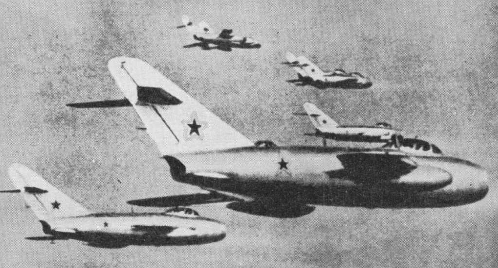
Early in 1949, in parallel with work on the SD (MiG-l5bis), the MiG OKB launched a more thoroughgoing redesign of the basic MiG-15 as the SI, alias 1-330. The SI was intended to afford improved transonic behaviour, achieved by mating the existing fuselage (forward of the rear frame of the engine plenum chamber) with a lengthened rear fuselage and an entirely new wing possessing better compressibility charac¬teristics, having leading-edge sweep of 45 deg inboard and 42 deg outboard. A mark of identification was the MiG-17’s three boundary layer fences on each wing.
The Klimov VK-l engine of the SD was retained, together with the armament of one 37-mm and two 23-mm cannon. The first prototype, officially flown on 13 January 1950, allegedly attained M 1.03, but crashed in March 1950. Following the loss of the first prototype, a second and further improved prototype took over, the test programme being completed on 20 June 1951 and series production being ordered as the MiG-17. Production began with a day fighter model (NATO `Fresco-A’), which retained the VK-1 engine.
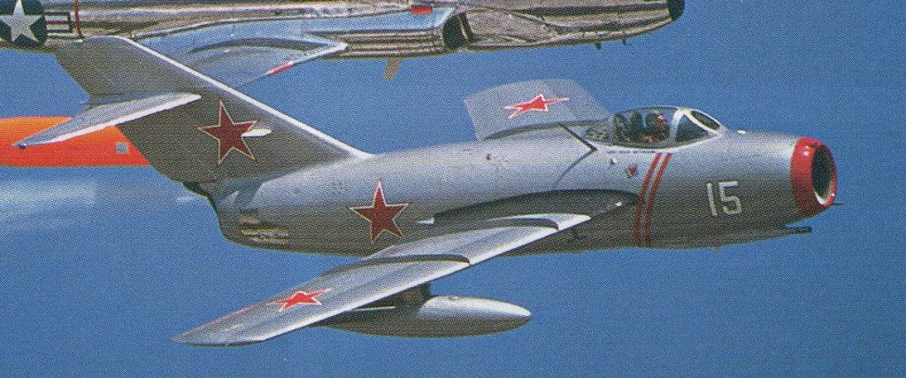
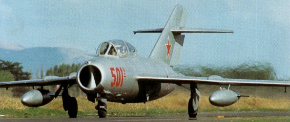
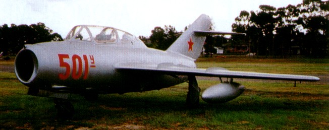
The MiG 17 was preferred to the Yak 50 and entered service with the Soviet air force in its Fresco A form during 1952. Its power¬plant was a Klimov VK 1 turbojet producing 2700 kg (5950 lb) of thrust, the same as in the MiG 15 bis, and the armament was similar: one 37 mm (1.46 in) N 37 cannon and a pair of 23 mm (0.90 in) NR 23s, aimed with the aid of a simple gyro gunsight. Air to surface armament could also be carried in the form of four UV 8 57 pods each containing eight 5.5 cm (2.16 in) S 5 rockets, two 21 cm (8.26 in) rockets, two 250 kg (551 1b) bombs or 240 litre (53 Imp gal) drop tanks. The use of steel underwing beams allowed two rocket pods or bombs to be carried inboard, with drop tanks on the outboard pylons.
Fresco B was the MiG-17P, flown as a prototype in 1951, fitted with an S band ‘Izumrud’ (Emerald) radar, known as Scan Fix in the West, with the main dish mounted on the intake splitter and the rang¬ing element housed above in the lip discardingd the 37-mm cannon in favour of a third 23-mm weapon. The fuselage was lengthened by 127 mm (5 in) and the cockpit glazing was modified to cater for additional displays. In the event, production of the MiG-17P was to be limited pending availability of the afterburning VK-1F engine.
Experimental versions included the SN, a ground attack model of the VK-1-engined fighter, which, flown in November 1953, featured lateral air intakes and twin 23-mm nose-mounted cannon which could be hydraulically elevated or depressed (± 40 deg). Another, the SP-2 flown in 1951, was a limited all-weather version with a higher-powered Korshun (Kite) search radar and a twin 23-mm cannon armament. During the course of 1953, production of the MiG-17 gave place to the improved MiG-17F.
Availability of an afterburning version of the Klimov engine, the VK-1F offering 7,452 lb st (3 380 kgp) for three minutes, resulted in the SF, which, flown in 1951, was cleared for series production as the MiG-17F Fresco C (Forsirovannyi, or, literally, “boosted”) in April 1953. Apart from a cut-back rear fuselage exposing the variable nozzle, the MiG-17F featured shorter and deeper air brakes; those on the new variants were larger than their predecessors, mounted in a different position on the fuselage and operated by external jacks.
Large-scale production of the MiG-17F was paralleled by production of the similarly-powered MiG-17PF limited all-¬weather fighter with a trio of 23-mm cannon and (from the 26th aircraft) the improved RP-5 Izumrud radar in a bullet' radome at the centre of the nose air intake and in an extension on the upper lip of the intake. Subsequently, this S-band radar was superseded by an E/F-band version ofScan Fix’, which still gave neither a large antenna nor a wide angle of scan.
In 1953, gun armament was deleted from a MiG-I7PF and provision made for a quartet of K-S (ARS-212) beam-riding missiles mounted on underwing pylons, this version entering production in 1955 as the MiG-I7PFU (Usovershenstvovanny, or, literally, “improved”).
The MiG 17PF Fresco D entered service in 1955 and was fitted with progressively improved versions of Izurnrud/Scan Fix, operating in X band as well as the original S band, and in the MiG-17PFU Fresco E variant the gun armament was replaced by four beam riding AA 1 Alkali air to air mis¬siles carried on underwing pylons projecting forward of the leading edge. Some MiG-17s were fitted out for reconnaissance, with cameras in the forward fuselage and only two guns, and the type has increasingly been used for ground attack as it was replaced in the interception role.
The MiG-17PM (Nato Farmer D) being an all weather fighter carrying only air-to-air missles as armament.
Production of the MiG-17F and MiG-17PFU continued in the Soviet Union until 1958, and licence manufac¬ture of the MiG-17F was initiated in 1957 in Poland as the LIM-5P (licencyjny mysliwiec, or “licensed fighter”), remaining in production until 1960. The MiG-17F was in service with that country’s Soviet-dominated air force in the late 1950s. The lead company, WSK-PZL-Mielec, also carried out design work on various modified versions, some greatly altered. Production continued until 1961. Dedicated reconnaissance and ground attack variants evolved designated LIM-5R and LIM-6.
Polish production of the MiG-17PF (LIM-5M) being initiated in 1959 and continuing until 1961. Dedicated reconnaissance and ground attack variants evolved in Poland were designated LIM-5R and LIM-6. Licence production was also undertaken of the MiG-17F (as the Jian5) and MiG-17PF (Jian-5A) by Shenyang in China commencing late 1956, and a uniquely Chinese tandem two-seat advanced training version was developed as the JT-5.
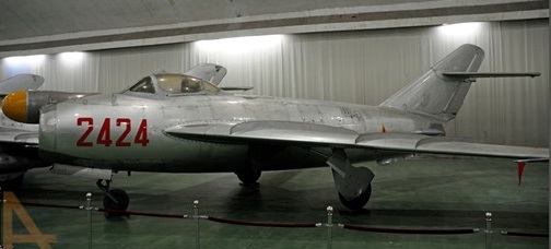
MiG-17 was license built China and known as Type-56, Dong Feng 101 and later is was dubbed J5 in Peoples Republic of China Air Force service. The first J5 prototype carried ‘Zhong-0101’.
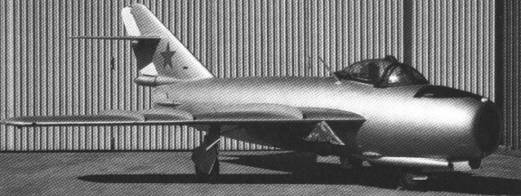
J5 prototype
J5
Some Polish LIM 5P’s were modified to LIM 5M standard by fitting additional fuel tanks and a twin wheel main undercarriage with low pressure tyres which retracted into a larger wing centre section built of rein-forced plastics. A relatively small number were converted, but many others were upgraded to LIM 6 standard by introducing a braking parachute, rocket assisted takeoff units and additional stores pylons. The LIM-6, together with the LIM 6bis having modified ordnance racks and the reconnaissance LIM 6R, remained in Polish service until replaced by the Su 20 Fitter C.
LIM-5
The earlier model had been constructed as the Czech S.104.
1721 Mikoyan-Gurevich Lim-5 R 1C-17-21
Licence production was undertaken of the MiG-17F (as the Jian-5) and MiG-17PF (Jian-5A) in China commencing late 1956, and a uniquely Chinese tandem two-seat advanced training version was developed as the JT-5.
A total of 11,015 was built (including licence production). The last one was built in 1958 but the type was exported more widely than any other Soviet military aircraft. The Fresco was withdrawn from Soviet air force service in the late 1960s but soldiers on in many parts of the world, typical ground-¬attack weapons comprising 250 kg (551 1b) bombs, UV 16 57 rocket pods and S 24 rockets.
Mikoyan-Gurevich MiG-17 Engine: 1 x Klimov VK-1 turbojet, 5,952 lbs thrust Wing Span: 31 ft 7 in Length: 36 ft 5 in Height: 12 ft 6 in Light weight: 8,646 lb Loaded weight: 11,803 lb Ceiling: 52,366 ft Speed: 696 mph Range: 1,290 miles (ferry) Crew: 1 Armament: 2 x 23mm cannon, 1 x 37 mm cannon, 4 x 57mm rocket pods
MiG-17 Engine: 1 x VK-1F(N) turbo-jet Wingspan: 9.6 m / 31 ft 6 in Length: 11.4 m / 37 ft 5 in Height: 3.8 m / 12 ft 6 in Wing area: 22.6 sq.m / 243.26 sq ft Max take-off weight: 5200 kg / 11464 lb Max. speed: 1114 km/h / 692 mph Ceiling: 15000 m / 49200 ft Range: 2000 km / 1243 miles Crew: 1 Armament: 1 x 37mm machine-guns, 2 x 23mm machine-guns, bombs or missiles
MiG-17 Engine: 1 x Klimov VK-1 turbojet, 5952 lb (later models) VK-1F, 4732 lb / afterburner-7452 lb) Max speed, 692 mph (1114 km/h) at 6,560 ft (2 000 m) Initial climb, 9,252 ft/min (47 m/sec) Range (with max external fuel), 1,336 mls (2150 km) Empty weight, 8,373 lb (3798 kg) Loaded weight (clean), 11,468 lb (5202 kg) Span, 31 ft 7 1/8 in (9,63m) Length, 36ft l1 1/3 in (1l,26m) Height, l2 ft5 5/8 in (3,80 m) Wing area, 243.26 sq ft (22,60 sq.m)
MIG-17F ‘Fresco-C’ Type: single-seat fighter Powerplant: one 3400-kg (7,495-lb) afterburning thrust Klimov VK-JF turbojet Maximum speed 1145 km/h (711 mph) at 3000m (9,845 ft) Initial climb rate 3900 m (12,795 ft) per minute Service ceiling 16600 m (54,460 ft) Range (with max external fuel): 1470 km (913 sm) Empty weight: 4100 kg (9,040 lb) Maximum take-off weight: 6700 kg (14,770 lb) Wingspan 9.63 m (31 ft 7 in) Length 11.09 m (36 ft 4½ in) Height 3.35 m (11 ft) Wing area 22.60 sq.m (243.3 sq ft) Armament: three 23-mm NR-23 cannon, plus four AA-1 ‘Alkali’ missiles or up to 500 kg (1, 102 lb) of external stores.
MiG-17P Engine: 1 x Klimov VK-1 turbojet, 5952 lb (later models) VK-1F, 4732 lb / afterburner-7452 lb) Wing span: 31 ft (9.45 m) Length: 36 ft 3 in (11.05 m) Height 11 ft (3.35 m) Empty wt: 9040 lb MAUW: 14,770 lb
MiG-17PF Wing span: 31 ft (9.45 m) Length: 36 ft 3 in (11.05 m) Height 11 ft (3.35 m) Empty wt: 9040 lb MAUW: 14,770 lb
MiG-17PM Wing span: 31 ft (9.45 m) Length: 36 ft 3 in (11.05 m) Height 11 ft (3.35 m) Empty wt: 9040 lb MAUW: 14,770 lb Armament: 4 x AA-1 missiles.
The I-310(S) was designed to meet a March 1946 requirement for a high-altitude day interceptor. The Mikoyan/Gurevich, Lavochkin and Yakovlev design bureau competed for the production contract, striving to meet the specification of a Mach 0.9 top speed, high rate of climb to 10000 m (32800 ft), good manoeuvrability at this height and above, a minimum of one hour’s duration and cannon armament, combined with simplicity of design and operation.
The need for a near sonic speed demanded the adoption of wing sweep, and the design team was able to draw on the expertise of Gurevich himself, in addition to other work carried out by Russian and German engineers. A swept forward wing layout was examined but discarded in favour of the swept back solution. The aircraft was designed around the RD-10A turbojet of 1000 kg (2205 lb) thrust, based on the German Jumo 004. A Russian designed powerplant with twice the thrust was in the pipeline and was expected to become available within a year, but the Anglo Soviet trade agreement of 1946 offered a more attractive possibility. The trade pact included the supply of 25 Rolls Royce Nene turbojets, most of which were allocated to the Klimov engine design bureau or to research establishments. One was supplied to the Mikoyan/Gurevich team and the MiG 15 was redesigned to accommodate the fatter Nene, which had a centrifugal compressor compared with the axial unit or the Russian engine under development, and which also produced greater thrust. The Rolls-Royce Nene immediately went into production at No 45 production factory in Moscow, designated RD-45 after the factory.
The layout involved air fed from a bifurcated nose intake via four ducts which passed either side of the cockpit and then over and under the unbroken wing centre section. The wing, of almost parallel chord, was swept back by 35 degrees at the leading edge and was built up from two main spars skinned with light alloy. The upper surfaces carried two full chord fences on each side and large Fowler flaps, set at 20 degrees for takeoff and 55 degrees for landing, were attached to the wing, just forward of the trailing edge. The ailerons were the only power operated aerodynamic controls.
The circular section fuselage was constructed in two halves which could be separated by means of quick release bolts at the attachment point for the rear wing spar, exposing the complete engine for maintenance. Air brakes were fitted on either side of the rear fuselage. The tailplane was swept back by 40 degrees and its incidence could be adjusted manually before takeoff. Two fuel tanks in the rear fuselage carried 90 litres (19.8 Imp gal) each, but the majority was contained in a 1225 litre (269 Imp gal) tank fitted between the wing spars. The undercarriage had a wide track 4 m (13 ft 1.5 in) to allow operation from rough fields; the levered suspension mainwheels retracted inwards to lie within the fork of the front main spar.
Navigation, communication and fire-control equipment was extremely simple but this solution proved to be the correct solution when the type was blooded in combat. A gyro gunsight (copied from the British GGS Mk 2) with a maximum range of 800 m (875 yards) was used to aim the two 23 mm (0.90¬in) NS 23 cannon mounted in a pack under the nose. This arrangement was later replaced by a single 37 mm (1.46 in) N 37 cannon with 40 rounds on the right hand side and a pair of NS 23s with 80 rounds each on the left. The wing hardpoints were stressed to carry up to 500 kg (1102 lb) of bombs, although two weapons of 100 kg (220 lb) each were more usual, and rockets were also fitted. Alternatively, auxiliary fuel tanks could be carried to increase endurance.
It seems likely that the first prototype of the MiG-15, designated I 310, made its maiden flight in July 1947, but crashed during low speed trials. Several design changes were introduced as a result, including the adoption of 2 degrees of wing anhedral in place of the dihedral layout, installation of wing fences and several changes to the back end. The rear fuselage was shortened and the jet pipe cut back to reduce the amount of engine power being lost, the tailplane was removed from the top of the fin and repositioned two thirds of the way up, and the fin itself was swept back by 56 degrees. The first of two replacement prototypes, the S-01, was flown on 30 December 1947. As the I 350 prototype, it flew for the first time in September 1953.
The revised design was far from perfect – it tended to enter a spin from a tight turn, necessitating the fitting of recovery rockets but it was apparent that the layout was basically sound. The Mikoyan/Gurevich team had six months’ headway over their competitors, and this proved decisive, although both the La 168 and Yak 30 proceeded to the flight-test stage and the former entered limited production.
Reverse engineering of the Nene by Vladimir Klimov’s bureau had paralleled design development of the I-310, and as the RD-45 of 4,850 lb st (2 200 kgp), this engine powered the initial series fighter, which, as the MiG-15, was cleared for production in March 1948 (NATO Fagot), the first pre-series aircraft being delivered to the NII for evaluation seven weeks later, on 10 May.
Early production MiG-15s powered by the RD 45, copied from the Nene, reached the squadrons before the end of 1948. The RD 45F (Forsirovanny, meaning boosted), uprated from 2200 kg (4850 lb) to 2270 kg (5000 lb) thrust for take¬off, soon replaced the earlier powerplant at an early production stage. Armament comprising one 37-mm N-37 and two 23-mm NS-23KM cannon.
Production under licence was begun in Poland as the LlM-1 and in Czechoslovakia as the S-102.
Variants of the RD-45F-powered fighter included the MiG-15PB escort fighter with two 132 Imp gal (600 lt) underwing slipper tanks, the MiG-15P with a pre-series Izumrud (Emerald) radar and the MiG-15SV with faster-firing NR-23 cannon, none of these being built in quantity.
A structural reappraisal of the basic MiG-15 resulting in a 198 lb (90 kg) weight reduction, minor aerodynamic changes, upgraded equipment and a Klimov-developed VK-1 turbojet (origi¬nally designated RD 45FA) rated at 5,952 lb st (2 700 kgp) for takeoff, or 3000 kg (6615 lb) with water injection produced the MiG-15SD flown in September 1949. With some further changes (which in¬cluded modifications to the ailerons and air brakes) this was placed in production in the following year as the MiG-15bis. The engine’s external dimensions remained the same, but the mass flow was increased and the larger diameter hot end resulted in dry weight rising from 870 kg (1918 lb) in the RD 45 to 875 kg (1930 lb) in the VK 1. Fuel capacity was increased by 160 litres (35 Imp gal) and improved equipment was fitted. Perforated flaps were therefore adopted to save airframe weight, offsetting increases in other areas. Late production models of the MiG-15bis, which was the variant built in the largest numbers, carried 23 mm (0.90 in) NR 23 revolver cannon in place of the slow firing NS 23s. Polish and Czech versions were designated LIM-2 and S-103.
Lim-2
The MiG 15bis was followed by the two seat MiG-15UTI, code¬named Midget, with the instructor sitting behind and slightly above his pupil. Some fuel capacity was sacrificed, and the top speed dropped slightly. The principal production version of the basic design, with several thousand being built until late 1951, plus others licence-built in Czechoslovakia and Poland (as the LIM-3).
LIM-3
The MiG-15bis standardised on an armament of two 23-mm NR-23 cannon and one 37-mm N-37 cannon.
Limited all-weather versions with Izumrud radar included the MiG-15SP-1 and SP-2. The two seater was also used for ejection seat experiments and formed the basis of the SP 5, the first all-weather fighter variant. An Izumrud (Emerald) fire control radar (NATO code name Scan Fix) was fitted, the antenna being mounted in a bullet fairing in the centre of the intake splitter. A complementary ranging radar was installed in the top lip of the intake. The definitive all weather fighter variant, the MiG-15P, was, however, a single seater derived from the MiG-15bis.
Other experimental models were the MiG-15SU for ground attack and featuring a pack containing cannon angled to fire downward, the MiG-15bisSB (ISh) intended for the shturmovik role and the MiG-15bisS escort fighter with 132 Imp gal (600 1t) slipper tanks, reduced armament and other changes.
A reconnaissance version, the MiG-15bisR with full armament and fitted with a single nose mounted vertical camera below the gun magazines was developed for high altitude sorties over Korea and was additionally employed in Europe.
A further variant was the MiG-15SB, which had twin beams extending from the wing leading edges to carry two 100 kg (220 1b) bombs, eight 55 mm (2.16 in) rockets or auxiliary fuel tanks. Rockets were fitted to reduce the takeoff run and a braking parachute similarly shortened the landing roll.
Production in the Soviet Union ended in 1953.
On 10 March 1953, five days after a Polish pilot had defected with his MiG-15 to the Danish island of Bornholm, two Czechoslovakian MiGs attacked two American F-84G Thunderjets over Regensburg in Bavaria. One of the Thunderjets was shot down by the 23mm and 37mm cannon of one of the MiGs. The pilot ejected safely over Czechoslovakian territory.
The last RB-29 was shot down by two MiG-15s above the east coast of Hokkaido, Japan, on 4 September 1954. The aircraft allegedly flew over Soviet territory on the Pacific coast, according to the Sovies. Ten or elevel of the crew survived.
One of the most widely used jet fighters of all time, the MiG-15bis was also manufactured in China (as the Shenyang F-2, and the MiG-15UTI as the Shenyang FT-2), Czechoslovakia (Mig-15bis as the Aero Vodochody S-103 and the Mig-15UTI as the CS-102) and Poland Czechoslovakia (Mig-15bis as the PZL-Mielec Lim-2 and the Mig-15UTI as the SBLim-1) in considerable numbers and it is known to have served with close to 30 air arms throughout the world as a front-line fighter and as an advanced trainer.
Large numbers (over 1,000) of early versions were supplied to China and North Korea, entering combat in 1951. No Allied fighter could stay with it and even the technically superior F-86 had inferior climb, ceiling and high-altitude turn radius. Many thousands (14,000+) of all versions were built, and the MiG-15 remained an invaluable aircraft for air forces with little jet experience, being supplied to at least 18.
The MiG 15 took part in the first ever all jet air combat when one was destroyed by a Lockheed F 80 Shooting Star of the US Air Force over Korea on November 7, 1950, some six days after the Russian type was deployed to that theatre. The Soviet aircraft was more manoeuvrable and had a higher ceiling than its US adversaries, and the slow ¬firing but hard hitting cannon carried a heavier punch than the machine guns of the opposing fighters. The USAF’s response was to introduce the North American F 86A Sabre, which scored its first MiG kill on December 17, 1950. The North Korean and Chinese pilots could not hope to match the experience of their adversaries, and on May 20, 1951, Capt James Jabara bagged his fifth and sixth MiG 15s to become the first jet ace. The USAF alone claimed 792 MiG 15s destroyed over Korea, while the US Navy also notched up a creditable score, bringing the claimed kill to loss ratio to about 12:1.
MiG-15 Engine: 1 x Klimov RD-45F, 5,005 lb st (2270 kgp) Max speed, 648 mph (1043 km/h) at 9,845 ft (3000 m) Max initial climb, 8,268 ft/min (42 m/sec) Range (clean), 882 mls (1 420 km) at 236 mph (380 km/h) at 39,370 ft (12 000 m) Empty weight, 7,456 lb (3 382 kg) Loaded weight (clean), 10,595 lb (4 806 kg) Span, 33 ft 1 in (10,08 m) Length, 32 ft 1¼ in (10,04 m) Height, 12 ft 1 2/3 in (3,70 m) Wing area, 221.75 sq ft (20,60 sq.m).
Engine: 1 x VK-1 turbo-jet, 26.5kN / 5950 lb Wingspan: 10.1 m / 33 ft 2 in Wing area: 20.6 sq.m / 221.74 sq ft Length: 10.1 m / 33 ft 2 in Height: 3.7 m / 11 ft 2 in Empty weight: 13,249 lb Max take-off weight: 4960 kg / 10935 lb Max. speed: 1076 km/h / 669 mph Max ROC: 19,400 fpm Ceiling: 16000 m / 52500 ft Range w/max.fuel: 2000 km / 1243 miles Range w/max.payload: 1400 km / 870 miles Armament: 1 x 37mm cannon, 2 x 23mm machine-guns, 400kg of bombs or missiles Crew: 1
MiG-15P Equipment: Izumrud (Emerald) radar.
MiG¬-15PB Type: escort fighter Fuel cap: two 132 Imp gal (600 1t) underwing slipper tanks
MiG-15SV Armament: faster-firing NR-23 cannon
MiG-l5bis Powerplant: one 2700-kg (5,952-lb) thrust Klimov VK-1 turbojet / later models one 6990-lb thrust Klimov VK-1A turbojet. Maximum speed 1100 km/h (684 mph) at 12000 m (39,370 ft) Initial climb rate 3500 m (11,800 ft) per minute Service ceiling 15550 m(51,015 ft) Ferry range 2000 km (1,242 miles) Empty weight 3400 kg (7,495 lb) Maximum take-off 5785 kg(12,756 lb) Wingspan 10.08 m (33 ft 0¾ in) Length 11.05 m (36 ft 3¼ in) Height 3.40 m(11 ft 1¾ in) Wing area 20.60 sq.m (221.7 sq.ft) Armament: one 37-mm NR-37 cannon and two 23-mm NR-23 cannon, plus up to 1000 kg (2,205 lb) of external stores.
MiG-15Bis (SD) Max speed, 692 mph (1114 km/h) at 7,220 ft (2 200 m) Time to 16,405 ft (5 000 m), 2.1 min. Range (clean), 826 mls (1330 km) Empty weight, 8,115 lb (3 681 kg) Loaded weight (clean), 11,175 lb (5069 kg) Span, 33 ft 1 in (10,08 m) Length, 35 ft 7½ in (10,86 m) Height, 12 ft 1 2/3 in (3,70 m) Wing area, 221.75 sq ft (20,60 sq.m) Armament: two 23-mm NR-23 cannon and one 37-mm N-37 cannon.
Engine one 7,452-lb Klimov VK- 1F turbojet Gross wt. 12,000 lb Empty wt. 8,115 lb Max speed 668 mph Range 450 nm Ceiling 50,855 ft Seats 1-2.
MiG-15UTI Engine: LIS-2, 5500 lb thrust. Fuel cap: Internal: 1000 lt, external 2 x 400 lt. ROC: 6000+ fpm. Service ceiling: 48,000 ft. Loading: Clean, +8g, With drop tanks full, +4g. Max speed: 570 kts (M 0.92), with drop tanks, 430 kts. Stall: 110-103 kts.
MiG-15UTI Type: Two seat fighter/trainer Engine: One Klimov RD-45 turbojet, 5,005 lbs thrust Empty weight: 7,900 lb Loaded weight: 10,935 lb Wing Span: 33 ft 1 in Length: 33 ft 2 in Height: 12 ft 2 in Ceiling: 50,580 ft Speed: 668 mph Range: 1,225 miles (ferry) Armament: 2 x 23mm cannon, 1 x 37 mm cannon, 2 x 100 kg bombs or rockets
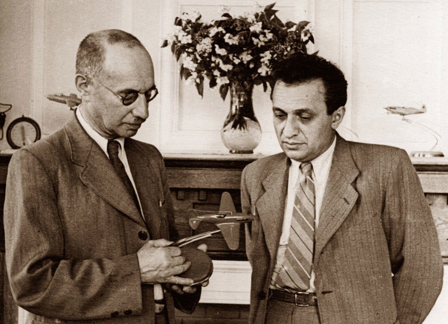
Mikhail Iosifovich Gurevich and Artem Ivanovich Mikoyan with a model of the MiG-3 fighter
A. Mikoyan and G. Gurevich design bureau established December 1939; still operating in 1990 as MAPO “MiG” as part of MIG “MAPO-M” organization, although Gurevich retired in early 1960s and Mikoyan died December 9,1970.
MiG-1 fighters with AM-35 engine produced 1940-1941; developed MiG-3 produced until 1942. First jet aircraft built in quantity was MiG-9 with twin RD-20 (BMW 003A) engines, flown 24 April 1946. Swept-wing MiG-15 with Russian copy of Rolls-Royce Nene introduced 1947, built under license in Czechoslovakia and Poland. Followed by approximately 9,000 of derived MiG-17, with redesigned wing, manufactured 1950-1957. Twin Mikulin AM-5-powered MiG-19 flown September 1953, built under license in Czechoslovakia, Poland, and China. Superseded by delta-winged MiG-21, in service in the USSR from 1959 and, when built in India, was first Russian aircraft manufactured in non-communist country.
Col-Gen Mikoyan died in 1970.
As ANPK “MiG” named after A.I. Mikoyan Aviation Scientific- Production Complex, produced MiG-23 (4,278 constructed 1969-1985; also built in India) and MiG-27 (over 900 between 1973 and 1983) related variable-geometry fighter and ground-attack aircraft, MiG-25 Mach 2.8+ reconnaissance aircraft and interceptor (some 1,200 built up to 1985), and MiG-31 long-range interceptor (about 400, operational from 1983).
MAPO ‘MiG’ produced MiG-21 upgrade as MiG-21 -93, MiG-29 Fulcrum lightweight close-air-combat fighter (first flown October 1977 and over 1,500 built, serving since 1983), improved MiG-29M (first flown April 1986) and MiG-33 export version, MiG-29K shipborne fighter prototype (first flown July 1988, first landing on aircraft carrier Admiral KuznetsovNovember 1989, and development restarted in 1996 after earlier program halt), MiG-35 multirole fighter (first flight 1999?), MiG 1-44 uniquely configured newgeneration combat aircraft (first seen February 1999), and MiG-AT/UTS/AC series of advanced and combat trainers. MiG-301/321 are reported hypersonic reconnaissance aircraft, thought to be under development. Also developing MiG-110 light multipurpose transport and MiG-115 and MiG-125 transports.
Migavia – the first national aircraft manufacturer in Russia aircraft corporations. RAC “MiG” is integrated company in which all technologies of design, production and improvement of aircraft are collected together in one legal frame. Corporation Migavia holds the shares of other corporations which are included into the complex of firms developing and producing the aircraft engines.
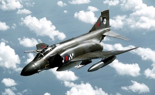
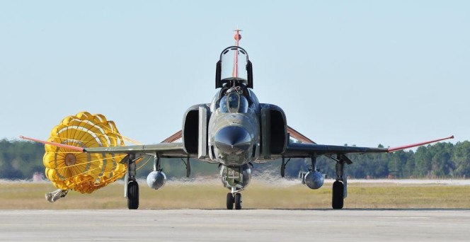
The low wings are swept back at 45 degrees, swept-back tail surfaces and 23 degrees anhedral on the one-piece all-moving tailplane. The wings have a ‘dog-tooth’ leading edge and dihedral on the outer panels which fold upwards for stowage. The ailerons move only down and are supplemented by spoilers on the upper surface of each wing. Trailing-edge flaps and small leading-edge flaps are blown. The tricycle undercarriage has a single wheel on each main unit and twin wheels on the nose unit. The mains retract inward into the wings and the nose wheels retract rearwards. A fire-control radar is in the nose, with infra-red equipment in a small bulge underneath.
The first flight for the F4H-1 Phantom prototype came on 27 May 1958. This aircraft differed from the 1955 mock-up mainly in the flying surfaces and around the jet intakes.
To protect against suspected lateral instability, the outer panels of the wings were canted upwards and the anhedral already planned for the tailplanes was increased. The jet intakes were enlarged and the edges cut back from the top to bottom.
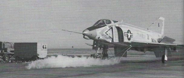
The sixth Phantom protype (BuNo 143391) was used for initial catapult launching testing.
sixth Phantom prototype (BuNo 143391) Feb 1960
By February 1960 a second missile had been added with an IR sensor, and an AAA-4 seeker was fitted under the radome of the F4H-1’s 24in antenna APQ-50 search radar.
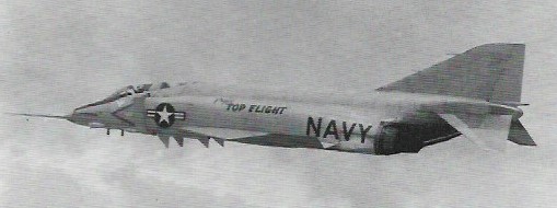
In late 1959, after it had been relieved of primary test responsibilities by the four remaining RTD&E airframes, the first Phantom far assigned to Project ‘Top Flight’, for a manned aircraft altitude record. On 6 December 1959 it reached 98,557 ft, breaking the previous Russian record by more than 4000ft.
Operation Top Flight
Powered by two 7711kg afterburning thrust General Electric J79-GE-8 engines. The first Phantom attained a speed record of 2585km/h on 22 November 1961, and a low-altitude speed record of 1452km/h on 20 August 1962.
During the testing of early Phantoms, some problems had been encountered with the original design of the intake, and in an attempt to improve airflow at all speeds a number of different configurations were tried. Here the splitter plate has been enlarged and the rake in the leading edge eliminated.
Of the 47 F4H-1/F-4As, 27 were assigned to test duties, the remainder going to training squadrons.
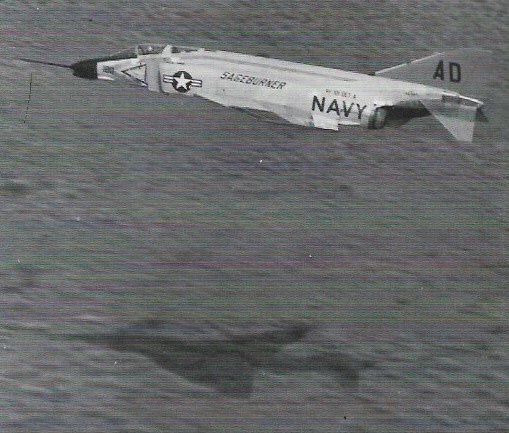
Eleventh Phantom BuNo 145310 with another variation in splitter plate and intake leading-edge design, and extended cooling intake behind radome which replaced NACA-style flush inlet of earlier prototypes.
The first squadron to receive F4H-1s was the ‘Grim Reapers’ of VF-101. The eleventh prototype was re-assigned from RTD&E to Det A of VF-101 in 1961.
Aircraft 145310 in August 1951 was in Operation Sageburner, a high-speed, low altitude, cross-country test run from San Diego, California, to NAS Oceana, Virginia.
Operation Sageburner
Aircraft 145310 was again on test duties in June 1963, by now designated F-4A.
Aircraft 145310 June 1963
The F-4B differed from the -A with a larger radar, the 32in-diameter APQ-72 introduced on a few F-4As, became standard, along with the requisite larger radome; the back seat was raised; and the entire canopy redesign was altered to give better forward vision for both crewmen. F-4Bs were also fitted with uprated engines, J79-GE-8s, in place of the -A’s -2s.
F-4B BuNo 149449
F-4B BuNo 149449 was assigned Project ‘High Jump’ to break the world’s time-to-climb records. During April 1962 new records were set at all eight recognised height increments between 3000 and 30,000m, reaching 30,000m in 371.43 seconds.
Production of the F 4B amounted to 649 aircraft. A large number of the F 4Bs have since been updated to F 4N standard
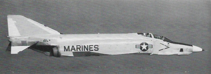
The RF-4B reconnaissance derivative served only with the US Marine Corps. The RF-4B was the second photo reconnaissance version of the Phantom, being a standard F-4B fitted with the nose developed for the Air Force F-4C. The first was RF-4B BuNo 151975t.
RF-4B BuNo 151975t March 1965
Photo Phantoms exchanged the large APQ-72 for a smaller APQ-99 radar.
The USAF reached an agreement with the Navy to take 27 more F-4Bs off the assembly line, all to be re-designated F-4C. A series of changes to the basic F-4B were implemented to make the Phantom more suitable for land-based service. These included larger, low-pressure mainwheel tyres (necessitating the thickening of the wing root) and the fitting of full dual controls and cartridge starters. The Navy retractable refuelling probe was replaced by a receptacle behind the cockpit.
The fourth F-4C 63-7410 on 27 Jan 64
The F-4C (F-110A) Phantom was the initial version for the USAF. The USAF’s Phantom II program was first designated F-110A Spectre but this name was later dropped and the USAF’s Phantom II was designated F-4C. The USAF F-4C made its first flight on May 27, 1963, and production deliveries began in November 1963 and the F-4C became operational with the 12th and 15th Tactical Fighter Wings at MacDill AFB, Florida, in January 1964. The F 4C was powered by J79 GE 15 engines.
Although very similar to the US Navy’s F-4B, it included some slight differences to make the aircraft suitable for air force use. Some of the items are: 1. The probe-and-drogue method of in-flight refuelling favoured by the US Navy was discarded in favour of the standard USAF boom’ method. 2. Full flying controls and instrumentation were duplicated in the rear cockpit. 3. In order to allow use from un-sophisticated airfields an anti-skid braking system was fitted, which included the use of thicker main-wheels. 4. The USAF version could carry a greater variety of external wea¬ponry.
The aircraft has flown a lot of combat mission in South-East Asia during the Vietnam War and has claimed 277 air-to-air combat victories.
During the Vietnam War in 1967 production was 72 Phantom IIs a month. 583 F 4Cs were built. 40 were transferred to Spain.
The service-test YRF-4C (YRF-110A) led to the RF-4C (RF-110A), 499 of which were constructed for the photo-reconnaissance role. Consideration was given to the possibility of developing a reconnaissance configured variant of the McDonnell Douglas F-4 Phantom at an early stage in the type’s operational career, but it was not until the US Air Force selected, the basic fighter model to equip Tactical Air Command units that this proposal began to move ahead rapidly. Known by the designation RF-4C, the resulting aircraft flew in prototype form for the first time on 8 August 1963, the last of which was formally handed over to the USAF over 10 years later, on 16 January 1974.
Easily recognised by the modified nose section which contains cameras and other reconnaissance sensors, the RF-4C entered operational service at Shaw AFB, South Carolina, in September 1964, although nearly a year passed before the first unit could be considered as combat ready. When that milestone was reached, overseas deployment followed quickly, aircraft being dispatched to South East Asia for combat duty by the end of 1965, and the RF-4C remaining in use as the principal tactical reconnaissance tool for the remainder of the Vietnam War.
The second reconnaissance model to appear, designated RF-4B, was intended specifically for service with the US Marine Corps and this made its maiden flight on 12 March 1965 with deliveries to El Toro, California, following just two months later. A total of 46 RF-4Bs was supplied to this service, and were the subject of modification and life-extension programmes.
By the mid-1960s, the Phantom was just about the best-known fighter in the world. On 2 January 1967 in Operation ‘Bolo’, F-4Cs of the 8th TFW under Colonel Robin Olds shot down seven North Vietnamese MiGs. Increasingly, F-4Ds took over from the Republic F-105 the job of bringing ordnance to bear on Vietnamese ground targets.
F-4 Phantom IIs in Israeli service are claimed to have shot down 116 aircraft during a number of conflicts.
Some F 4Cs were converted into EF 4Cs under the ‘Wild Weasel’ programme to suppress enemy weapon radar systems.
The F-4D differed from the -4C externally only in having a slightly larger nose cross-section, in order to house the new APQ-109 radar with its improved air-to-ground capability. A new weapons release computer and 30kVA generator occupied the forward fuselage fuel cell, reducing fuel capacity and range.
The F-4D Phantom fighter-bomber introduced a capability to deliver precision-guided munitions (PGM), or ‘smart’ bombs. Some 825 were built, including 32 delivered new to Iran and 36 transferred to South Korea.
On 28 March 1974, the Royal Hellenic Air Force received the first of 38 F-4 Phantom IIs ordered.
Once in action in Vietnam in 1965, the Phantom seemed to need a gun to augment its missile armament in close-quarter battles with MiGs. The SUU-16/A 20mm external gun pod was an interim measure. The F-4E, first flown on 7 August 1965, introduced the 17,900 lb thrust (with afterburning) General Electric J79-GE-17 engines but its principal change was the internally-mounted M61A1 20mm cannon. The F-4E established a 2.5-to-1 kill advantage over North Vietnamese MiG-17, MiG-19 and MiG-21 fighters. Armament is one 20 mm M61A 1 multi barrel cannon and eight air to air missiles or up to 16,000 lb (7,250 kg) of ground attack weapons.
The F-4E became the definitive Phantom, and 1,397 rolled off the line. Examples were supplied to Australia (on loan), Greece, Iran, Israel, Turkey, South Korea and West Germany. The RF-4E was an export reconnaissance derivative, supplied to Greece, Iran, Israel, Japan and West Germany.
As well as producing reconnaissance Phantoms for the home market, McDonnell Douglas also developed the RF-4E variant, initially in response to a Luftwaffe requirement for 88 aircraft to undertake this mission. Flown for the first time on 15 September 1970, the RF-4E subsequently also joined the air arms of Greece, Iran, Israel, Japan and Turkey, just over 160 aircraft of this type being built before production ceased.
The RF 4E reconnaissance version and the F 4M RAF version carrys the service designation FGR.Mk 2.
The F-4F was a specialised air superiority version for the West German Luftwaffe, and 175 were delivered. The F-4G designation had been used initially for 12 aircraft taken from the US Navy F-4B production line. They had the two-way ASW-21 data-link system for automated carrier landings, and all later reverted to F-4B standard. In the 1970s, the F-4G appellation was used again for the US Air Force’s ‘Advanced Wild Weasel’ electronic warfare aircraft, 116 of which were converted from F-4E standard. Originally seen as a counter to enemy SAM missile sites and associated radars, the F-4G now carries out a wide portfolio of electronic missions. Aircraft are stationed as far afield as the 3rd TFW Clark Field, Philippines, and 52nd TFW, Spangdahlem AB, West Germany.
The F-4J was an improved production fighter for the US Navy with 8119kg afterburning thrust J79-GE-10 engines, enlarged wing and improved avionics.
On the 1st of November 1968, Japan signed a letter of agreement with Mc Donnell Douglas and it was also announced that it would become one of the few countries worldwide that was going to license-produce this aircraft. Over the following years, the Nihon Koku Jietai (Japan Air Self-Defence Force) received a total of 154 F-4EJ and RF-4Es. The F-4EJs (the export version for Japan) were mostly similar to the F-4Es, although the Japanese aircraft had their in-flight refuelling and ground-attack capabilities removed to align with Japan’s defensive posture, the F-4EJs were delivered without the AN/AJB-7 bombing computer system.
The first two F-4EJs (JASDF serials 17-8301 and 17-8302) were built by McDonnell Douglas in St Louis and first flew on January 14, 1971. The next 11 F-4EJs (JASDF serials 27-8303/8307, 37-8307/8310, and 47-8311/8313) were built by McDonnell Douglas in kit form and were assembled in Japan by Mitsubishi Heavy Industries, Ltd. The first Japanese-assembled aircraft (27-8303) flew on May 12, 1972. Subsequently, Mitsubishi built all the rest 127 F-4EJ during the following nine years. The last example was delivered to the JASDF on May 20, 1981. This was the last F-4 ever built in the world.
Japan also acquired 14 RF-4Es built by McDonnell Douglas to serve in the reconnaissance role. These RF-4Es were delivered between November 1974 and June 1975. They were virtually identical to the USAF RF-4C, with the only differences being the deletion of certain equipment such as the radar homing and the warning suite which had not been released for export to Japan.
The F-4EJs entered service with the JASDF in August 1972 with a total of six squadrons operating the aircraft: the 301st, 302nd, 303rd, 304th, 305th and 306th squadrons. The RF-4Es equipped the 501st that had previously operated one of the less-well-known Sabre models, the RF-86F.
Mitsubishi was the prime contractor in a modernization programme for up to 110 of the JASDF’s fleet of F-4EJ Phantoms. Known as the F-4EJKai, the prototype updated aircraft flew in July 1984. Improvements include installation of a Westinghouse AN/APG-66J pulse-Doppler radar, a Kaiser/VDO headup display, a Litton LN-39 inertial navigation system, and a J/APR-4Kai radar warning receiver. The F-4EJKai will have a look-down capability, armed with AIM-9L Sidewinders and AIM-7F Sparrows, and will also be able to carry two ASM-1 anti-shipping missiles. Funding for the first eight production F-4EJKai conversions was authorised in the FY1987 budget. Aircraft not covered by the upgrade programme will be converted later to RF-4EJ reconnaissance fighter stan¬dard.
Israel Aircraft Industries has flown a prototype conversion with one PW1120 turbofan and one standard J79 turbojet. This aircraft flew in July 1986, and has since been further modified and flown with two PW1120s. Flight testing continues.
An improved version of the EF 4C has been developed as the F 4G Advanced Wild Weasel, being basically a modified F 4E equipped with special electronics and carrying air to surface missiles to detect and attack early warning and weapon radar systems. The first of 116 entered service in 1978.
During its bombing attacks on North Vietnam, the USAF proved the effectiveness of the ‘Wild Weasel’ concept; that is the use of specially-equipped aircraft flying with, or slightly in advance of the main attack and tasked with destruction or suppression of hostile radars, particularly those associated with SAM and AA gun guidance, Republic F-105G Thunderchiefs performed well in this role in the early 1970s and 35 FAC Phantoms were similarly converted in 1968-9, but when the specification for an Advanced ‘Wild Weasel’ aircraft was drawn up in 1975 the F-4E variant of the Phantom was selected as the basis for modification. Already established as one of the world’s most effective interceptor and fighter-bomber aircraft, the Phantom took to the mission with ease, becoming the McDonnell Douglas F-4G ‘Wild Weasel’ in the process. First requirement of a ‘Wild Weasel’ is to locate and classify enemy radars. This is undertaken by a McDonnell Douglas AN/APR-38 radar homing and warning system (RHAWS), the principal external features of which are a receiver and computer pod beneath the nose (replacing the Vulcan rotary cannon) and 56 antennae in a small fintip pod, on the fin sides, upper fuselage and other locations. Three cathode-ray tube displays in the rear cockpit (backed by digital readouts, aural warning system and indicator lights) provide the electronic warfare officer with a detailed picture of the tactical situation and automatically allocate attack priorities to the 15 most pressing threats in order of the danger which they represent. Weapons delivery is also aided by computer, allowing the F-4G to attack its target ‘blind’ with bombs, anti-radiation missiles and the latest AGM-65D Maverick which has infra-red TV-type guidance. There were 116 conversions to F-4G, these aircraft entering service in 1978 and including 24 based at Spangdahlem, West Germany, with the 81st RFS/52nd TFW for operations on the NATO Central Front.
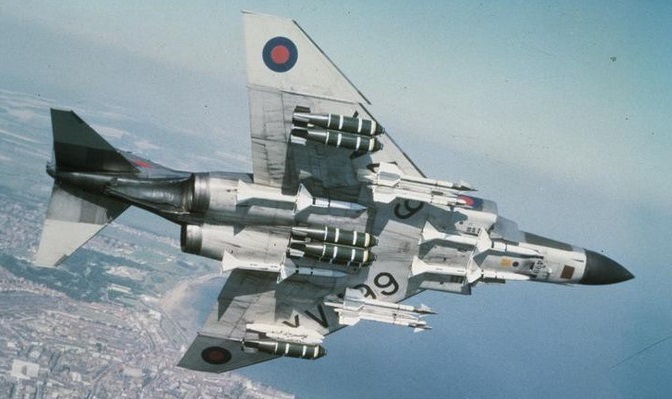
The F-4K was developed for the UK’s Royal Navy and the F-4M for the Royal Air Force, though both were operated by the RAF which, with expanded commitments following the 1982 Falklands war, has also inherited 15 ex-US Navy F-4Js.
Those supplied to the Royal Navy (F-4K) were powered by Rolls Royce Spey turbofan engines. Two versions of the Rolls Royce Spey-powered Phantom entered service with the Royal Air Force. The FG1 (the version also used by the Royal Navy) in the interceptor role and the FGR2 in the ground attack and tactical reconnaissance role in Germany. From 1977, all the Royal Air Force Phantoms were used exclusively as interceptor fighters over United Kingdom air-space.
Originally, adapting F-4B to smaller British carriers seemed to require only a change from GE J79 to RR Spey engines would be needed. By 1964, more modifications were required including drooped ailerons to slow landing speed, extended wing area and fuel capacity and others. These delayed closing the deal to reconfigure feasibility and costs.
Great Britain bought fifty two Phantom FG1s and 118 Phantom FGR2s.
With the deployment of Phantoms to the South Atlantic in 1982 an additional order for 15 Phantoms was placed. These were second hand United States Navy F-4Js fitted with General Electric F-79 engines. After an extensive refurbishment and the fitting of some British equipment they were designated F-4J(UK).
The collapse of the threat from the Eastern Europe led to an accelerated run down of the Phantom fleet and the last unit disbanded at the end of September 1992.
The German Luftwaffe was the biggest operator of the Phantom flying the F-4F ICE upgrade until the Eurofighter takes over its air defence role. Turkey and Greece were also still flying the F-4, their F-4E aircraft undergoing extensive upgrade work. Turkey was upgrading them to F-4E/2020 Terminator in cooperation with IAI. The Greek Air Force (HAF) upgrade program is known as Peace Icarus I&II and covered 40 aircraft. They also operated a number of RF-4 photo reconnaissance aircraft.
The Air National Guard was the last US operator of the F-4 until retirement in 1995/1996.
The EF-4B designation went to one airframe used for ECM training, and two modified, development airframes bore the NF-4B designation.
The F-4N is an upgraded ‘rebuild’ of the F-4B, and has in turn been converted to the QF-4N drone. The F-4S is an upgraded F-4J with wing manoeuvre slats and was the final Phantom variant to serve aboard an aircraft carrier, with VF-151 and -161 aboard the USS Midway.
Production ended in America after more than 5,050 had been delivered.
Operators: US Air Force, US Navy, US Marine Corps, Germany, United Kingdom, Turkey, Greece, Spain, Egypt, Iran, Israel, Australia, Japan, South Korea
By March 2000, 336 F4E and F4G airframes – most at Davis Monthan AFB, Arizona – had been identified for conversion to drones. The newer “G” and “E” models were chosen because their airframes typically have time remaining before USAF-regulated depot maintenance would be required for safe flight.
The fighters are flown to Mojave, Calif, where BAE Systems removes certain equipment and installs a drone autopilot, new computers, improved navigation systems and an onboard destruction package. Tails and wingtips are painted orange for easier visual acquisition during live-fire missions. Converting each F4 to a drone configuration costs approximately $2 million. Once QF-4s arrive it Tyndall AFB, they are classified in one of three roles: A manned flyer, flyable-storage drone, or a mission-ready drone. Some are sent to an 82nd ATRS detachment at Holloman AFB, N.M., to support Army and other aerial target requirements.
About 14 QF-4s are maintained as “manned” aircraft and flown regularly by USAF and Lockheed Martin pilots for mission rehearsals, proficiency and pilot upgrades.
Tyndall Air Force Base, Fla. (AFNS) — The 82nd Aerial Target Squadron received the last of the “new” QF-4 aerial targets on 19 November 2013.
The QF-4, Aircraft 68-0599, spent more than 20 years in the Air Force “Boneyard” at Davis-Monthan Air Force Base, Ariz., before being brought back to life for one last mission.
The supersonic, reusable QF-4 provides a realistic full-scale target for air-to-air weapons system evaluation, development and testing. Since the QF-4 replaced the QF-106 in 1998, more than 300 found a new purpose. The Phantoms began returning to work after the 309th Aerospace Maintenance and Regeneration Group reinstalled the parts to the aircrafts making them serviceable again. The next step involved contractors BAE Systems converting the F-4 to the QF-4, which would be flown remotely by highly-trained civil service pilots with an average of 4,000 flight hours.
The teamwork of contractors, civilian and military members contributed to more than 16,000 manned and 600 unmanned QF-4 missions. Ultimately, 250 of the Phantoms succeeded in their missions and been successively destroyed over the Gulf of Mexico and the ranges near Holloman Air Force Base, NM.
There are only about 60 QF-4s remaining in the program both at Tyndall AFB and Holloman AFB by the end of 2013. The limited availability of F-4s and the continuing advancement of fighter aircraft such as the F-22 Raptors are forcing a shift to the fourth generation QF-16, a converted F-16 Fighting Falcon that should be ready for use in 2014.
Production of the Phantom at St Louis eventually totalled 5057 complete machines, the last of which was flown away on Friday 26 October 1979. Eleven further F-4Ejs were provided a knock-down kits to Mitsubishi Industries in Japan, for a total of 5068 complete airframes. Japan brought the eventual total up to 5195 when the last F-4EJ was rolled out in May 1981.
F-4B (F4H-1) Engines: 2 x General Electric J79-GE-2A, 16,150 lb Wing span: 38 ft 5 in (11.7 m) Length: 58 ft 3 in (17.76 m) Height: 16 ft 3 in (4.96 m) Max TO wt: 54,600 lb (24,765 kg) Internal fuel capacity: 3665 gal External fuel capacity: 500 gal (under fuse) / 2×300 gal underwing. Max level speed: M2+.
F-4C (F-110A) Engine : 2 x General Electric J79-GE-8 (4950/7711kp), 75645 N Length : 62.828 ft / 19.15 m Height : 16.273 ft / 4.96 m Wingspan : 38.386 ft / 11.7 m Wing area : 530.019 sq.ft. / 49.24 sq.m Max take off weight : 54606.8 lb / 24765.0 kg Weight empty : 28003.5 lb / 12700.0 kg Max. speed : 1376 kt / 2548 km/h Cruising speed : 499 kt / 925 km/h Service ceiling : 70997 ft / 21640 m Cruising altitude : 40026 ft / 12200 m Wing load : 103.12 lb/sq.ft / 503.0 kg/sq.m Maximum range : 1998 nm / 3700 km Range : 1998 nm / 3700 km Range (max. weight) : 783 nm / 1450 km Crew : 2 Armament : 4x AIM 7E Sparrow III, 4x AIM 9 Sidewinder / 16,000 lb / 7250kg ext.
F-4D
F-4E Power Plant: Two General Electric J79-GE-17A axial-flow turbojets each with a normal continuous rating of 11,110 lb St (5044 kgp), a max continuous (30-mm) rating of 11,870 lb st (5 390 kgp) and an afterburner rating of 17,900 lb st (8 127 kgp) Fuel capacity, 1 225 US gal (46371) in seven bladder tanks in fuselage, 630 US gal (23851) in two integral wing tanks and up to 1,340 US gal (50721) in three drop tanks; max possible capacity, 3,333 US gal (12615 lt) Max speed, Mach= 2.17, 1,245 kts (2304km/h) at 36,000 ft (10 973 m) Max rate of climb (clean), 49,800 ft/mm (253 m/sec) Service ceiling (clean), 58,750 ft (17 907 m) Ferry range, 1,401 naut mls (2593 km) Range w/max.payload: 700 km / 435 miles Empty weight, 30,328 lb (13770 kg) Basic weight, 31,853 lb (14461 kg) Design weight (for 8.5g subsonic, 6.5g supersonic), 37,500 lb (17 025 kg) Design take-off weight (7.75g subsonic, 5.93g supersonic), 58,000 lb (26 332 kg) Max take-off weight, (5.17g subsonic, 3.95g supersonic), 61,795 lb (28 055 kg). Max. payload : 31476.4 lb / 14275.0 kg Span, 38 ft 4 in (11,68 m) Span folded, 27 ft 6 in (8,38 m) Length, 63 ft 0 in (19,20 m) Height, 16 ft 5 in (5,00 m) Undercarriage track, 17 ft 9 in (5,41 m) Wing area, 530 sq ft (49,24 sq.m) Aspect ratio, 2.82:1 Dihedral, zero on centre wing, 12 deg on outer panels Sweepback, 45 deg at quarter chord. Landing speed : 148 kt / 275 km/h Cruising speed : 504 kt / 934 km/h Initial climb rate: 29921.26 ft/min / 152.00 m/s Wing load : 114.6 lb/sq.ft / 559.0 kg/sq.m Crew : 2 Hardpoints: 9 Armament: One General Electric M61A1 multi-barrel 20-mm cannon under forward fuselage with 640 rounds. Provision for four AIM-7E-2 Sparrow missiles semi-recessed under fuselage. Centre line pylon up to 2,170-lb (986-kg) + up to 3,020-lb (1 371-kg) + four wing pylons / one AGM-45A Shrike or one Walleye ASM + inner pylons two AIM-4D Falcon or two AIM-9D or -9E Sidewinder AAMs.
F-4E(S)
F-4EJ Wing span: 38 ft 5 in (11.71 m) Max speed: M2.2.
F-4F Phantom II Engines: 2 x GE J79-GE-17A, 17,900 lb / 8119 kg thrust Span: 38 ft 7.5 in / 11.77 m Length: 63 ft 0 in / 19.20 m Height: 16 ft 5.5 in / 5.02 m Empty weight: 31,328 lb / 13,757 kg MTOW: 61,795 lb / 28,630 kg Wing area: 530 sq.ft / 49.24 sq.m Speed: 1433 mph / 2301 kph Ceiling: 58,750 ft / 17,905 m Range: 1424 mi / 2280 km Armament: 1 x 20mm Vulcan Bombload: 16,000 lb / 7257 kg ROC: 30,000 fpm / 9145 m/min Tactical radius: 700 mi / 1125 km Seats: 2
F-4G Wild Weasel’ Phantom Powerplant: two 8119-kg (17,900-1b) thrust General Electric J79-GE-17A afterburning turbojets. Maximum speed with external stores Mach 2 + Initial climb rate at maximum take-off weight 2003 m (6,570 ft per minute) Service ceiling 16580 m (54,400 ft) Combat radius 1145 km (712 miles). Empty weight 13757 kg (30,328 lb) Maximum take-off weight 28030 kg (61.795 lb) Span 11.77 m (38 ft 7½ in) Length 19,20 m (63 ft 0 in) Height 5.02 m (16 ft 5½ in) Wing area 49.2 sq.m (530 sq ft). Hardpoints: 7 Armament: up to 7258 kg (16, 000 lb)
F-4J
F-4J(UK)
F-4K (FG.Mk 1)
F-4M (FGR.Mk 2)
F-4N
F-4S
EF-4C
RF-4B
RF-4C Powerplant: two General Electric J79GE-15 turbojets, 7711-kg (17,000-lb) afterburning thrust. Maximum speed at low level 1464 km/h (910 mph) or Mach 1.19 Maximum speed at altitude 2414 kph (1,500 mph) or Mach 2.27 Ferry range 3700 km (2,300 miles) Empty weight 13290 kg (29,300 lb) Maximum take-off 26309 kg (58, 000 lb) Span 11, 71 m (38 ft 5 in) Length 19.20 m (63 ft 0 in) Height 5.02 m (16 ft 5 1/2 in) Wing area 49.24 sq.m (530 sq ft)
Though the 1950 penetration fighter competition among XF-88, XF-90 and YF-93A resulted in no production contract, the Strategic Air Command still wanted an escort fighter, its F-84F being seen as only an interim solution. McDonnell’s design team under Herman Barkey responded with the heaviest single-seat fighter ever built. Powered by two 5307kg Pratt & Whitney J57-P-13 turbojets, the F-101 would carry four 20mm cannon plus three Hughes GAR-ID or GAR-2A Falcon missiles or 127mm high-velocity aircraft rockets (HVAR) mounted on rotary bomb doors. A single-seater, with the two engines side-by-side, the wing has a 35 degree sweepback on the leading edge and distinctive ‘W’-shape trailing edge.
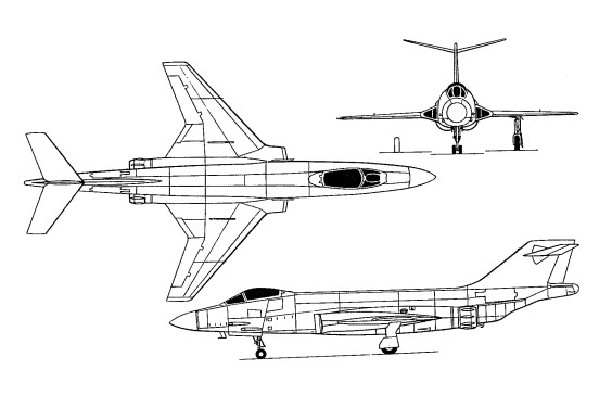
The F-101 has mid-set wings with 35 degree sweepback, and swept-back tail surfaces with a one piece all-moving tailplane mounted near the tip of the fin. Conventional ailerons, rudder and trailing edge flaps are fitted, with an airbrake on each side of the tail-boom. A tricycle undercarriage has single wheels on each main unit and twin wheels on the nose unit. The mains retract inward into the wings and the nose wheels retract forward. A fire-control radar is in the nose.
The first F-101A flew on 29 September 1954 at St Louis, and exceeded Mach 1 on its maiden flight. This was a production craft, there being no service-test machine. SAC dropped its requirement and the 77 F-101As built went to the Tactical Air Command. The first delivery was made 2 May 1957 to the 27th Tactical Fighter Wing. Seven of these airframes were later designated JF-101A while being used for temporary tests.
F-101A Voodoo
The first of two YRF-101A service-test reconnaissance Voodoos flew on 10 May 1956, followed by 35 RF-101A airframes delivered to TAC’s 363rd Tactical Reconnaissance Wing at Shaw AFB, South Carolina. The reconnaissance Voodoo had a lengthened nose with space for downward or oblique cameras and other sensors.
On 12 December 1957, Major Adrian E. Drew, USAF, established a World Air Speed Record of 1207.6 mph, in an F-101 Voodoo.
An RF-101A was shot down during the Cuban missile crisis of October 1962.
The F-101B Voodoo was developed by modifying the single seat F-101 fighter involved extending the fuselage forward to house a new weapons system and a second crewman to operate it. The bigger F-101B Voodoo was fitted with 5438kg Pratt & Whitney J-57-P-55 engines, with their characteristic large afterburners.
The first F-101B flew on 27 March 1957 at St Louis. For long-range intercept, it could carry two Douglas MB-1 Genie nuclear unguided rockets as well as three Falcons. Deliveries began on 18 March 1959 to the 60th Fighter Interceptor Squadron.
Eventually, the F-101B equipped 16 ADC squadrons, guarding against the Soviet bomber threat to North America. ANG units operated the F-101B between 1970 and 1982.
The JF-101B designation was applied to two machines used for temporary tests. One NF-101B was structurally modified for development work. Very late in their careers, with reconnaissance Voodoos still needed long after the interceptor variant was retired, 22 of the two-seat airframes were converted to RF-101B. The TF-101B was a version of the interceptor with full dual controls.
The F-101C single-seat tactical fighter differed from the F-101A primarily in having the capability to carry a US tactical nuclear weapon, and 47 were delivered to TAC.
The RF-101C, the first of which was flown 12 July 1957, was an improved development of the RF-101A; 166 went to TAC squadrons. The USAF began operating the RF-101C in South East Asia in 1964 and suffered its first combat loss on 21 November 1964 when an RF-101C of the 15th Tactical Reconnaissance Squadron was shot down over Laos.
Though not as much publicised as other combat types, the RF-101C remained in combat until 1970. No less than 31 airframes were lost in battle, plus another six to operational causes. In the mid-1960s, a few RF-101Cs served with the Nationalist Chinese air force, flying clandestine missions over the mainland.
Other Voodoo variants were the F-101F, the USAF designation for the CF-101F interceptor operated by Canadian forces; the RF-101G, a conversion of high-hour RF-101A airframes for reconnaissance duties with the Air National Guard; and the RF-101H, another reconnaissance conversion.
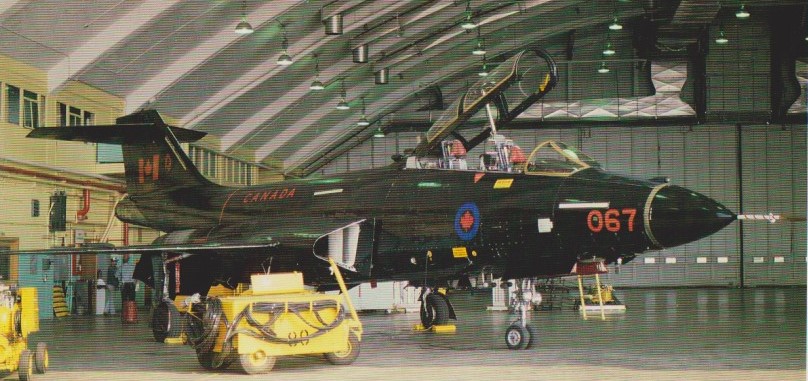
After the cancellation of the Avro Arrow in February 1959, Canada urgently needed a fast interceptor to meet the continued threat from manned Soviet bombers. By late 1959, the RCAF picked the Voodoo as the aircraft that best met Canada’s requirements. In June 1961, the RCAF agreed to purchase sixty six nearly new CF-101B Voodoos from existing USAF stocks. The deal transferred the aircraft to five front line squadrons and an OTU, to replace obsolete CF-100s.
In 1961 and 1962, 410 Cougar and 425 Alouette Squadrons of Bagotville, 409 Night Hawk Squadron of Comox, and 416 Lyns Squadron of Chatham were equipped with 66 Voodoos in total (55 CF-101B and 10 CF-101F), all built by McDonnell-Douglas.
At the beginning of the 1970’s, the aging CAF Voodoo fleet was exchanged for sixty six lower timed USAF Voodoos. These replacement aircraft were equipped with a superior missile control system. Even with the Voodoo fleet restored to its original size, serviceability began to be a problem. In 1977, the CAF launched a program to find a new fighter to replace the Voodoo and by April 1980, the search eventually narrowed down to the CF-18 Hornet.
Since the Summer of 1983 each of the four Voodoo Squadrons has been stood down. First 410 Squadron converted to the CF-18 OTU. 409 Squadron became the first operational CF-18 Sqn. 425 and 416 Squadrons received CF-18s in December 1984.
EF-101B 101067 “Electric” Voodoo
One aircraft remained in service. The CAF received Voodoo 191067 in the early 1980s and modified it to an EF-101B for ECM duties. The aircraft ws operated by 414 ‘Electronic Warfare’ Sqn and known as the “Electric” Voodoo. The EF-101B was retired by the end of 1986.
Most of the Voodoo fleet was phased-out by the end of 1984 and the last Voodoo flight anywhere was made in April 1987, when #101006 was delivered to CFB Chatham for display at CFB Cornwallis.
One F-101B appeared briefly on the US civil register, as N8234, used for thunderstorm research by Colorado State University.
Altogether 807 Voodoos were built for the USAF. The McDonnell Aircraft Co. manufactured 479 F-101B Voodoos in the United States, between 1957 and 1961.
F-101 Engines: 2 x P&W J-57-P-13, 52.0kN Max take-off weight: 18000-22250 kg / 39683 – 49053 lb Empty weight: 12700 kg / 27999 lb Wingspan: 12.1 m / 39 ft 8 in Length: 20.6 m / 67 ft 7 in Height: 5.5 m / 18 ft 1 in Wing area: 43.2 sq.m / 465.00 sq ft Max. speed: 1940 km/h / 1205 mph Cruise speed: 950 km/h / 590 mph Ceiling: 15800 m / 51850 ft Range w/max.fuel: 4800 km / 2983 miles Crew: 1 Armament: 4 x 20mm machine-guns, 15 missiles
F-101A Voodoo Long-range escort fighter Engines: 2x Pratt and Whitney J57 turbojets 10,000 lb. thrust with afterburners. Crew: 1 Wingspan: 39 ft. 8 in Length: 67 ft. 5 in Armament: 4×20 mm. cannon
F-101B Voodoo Engines: 2 x Pratt&Whitney J57-P-55, 53347 N / 16,900 lb Length: 67ft 5in / 20.54 m Height: 18.012 ft / 5.49 m Wingspan: 39ft 8in / 12.09 m Max take off weight: 46679.9 lb / 21170.0 kg Max. speed: 1060 kts / 1963 km/h / 1,134 mph at 35,000 feet Service ceiling: 52001 ft / 15850 m Max ROC: 14,000 fpm Range: 1350 nm / 2500 km Crew: 2 Armament: 3x Missile AIM-4E Super Falcon, 2x AIR-2A Genie
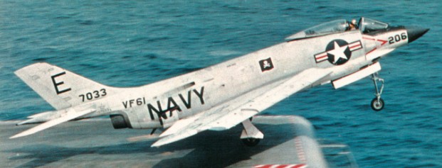
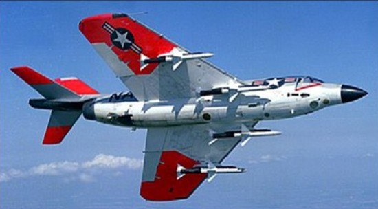
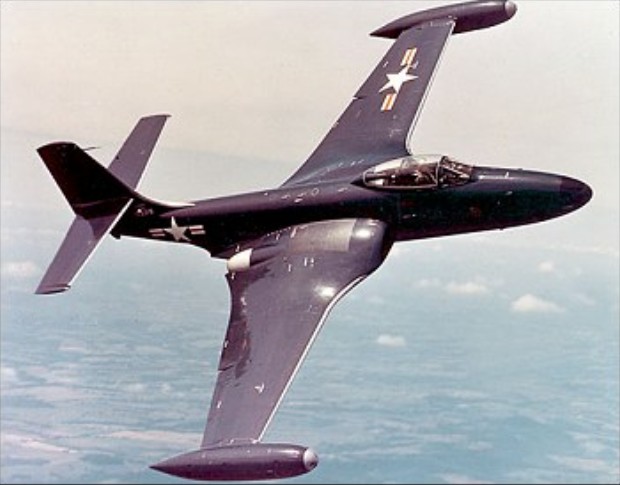
The prototype of the Demon naval fighter first flew on 7 August 1951 but proved to have poor stability, poor forward visibility and a low roll rate. These faults were corrected on the initial production model, but the poor reliability and performance of the J40 engine meant that most of the 58 built never flew.
The airframe had mid-set wings, swept-back at 45 degrees, swept-back tail surfaces and one-piece all-moving tailplane. The wings were fitted with leading edge slats and trailing edge slotted flaps. Airbrakes were in the upper surface of each wing root trailing edge and on the sides of the rear fuselage. The outer wings fold upward for storage. In-flight fuelling is fitted.
The tricycle undercarriage had a single wheel on each unit, the mains retracting inwards into the wings, and the nose wheel retracting rearward.
By June 1955 the F3H 2 had been produced with the Allison J71 engine, which still gave limited power. A modified afterburner system gave power in the range needed to make safe carrier landings.
They served with the US Navy in three versions – F3H-2N all-weather fighter, F3H-2M missile-armed day fighter, and F3H-2P for photo-reconnaissance.
The first naval fighter to be armed with guided missiles was the F3H-¬2M.
F3H-2 Demon Engine: 1 x Allison J71-A-2E turbo-jet, 62.23kN / 14,250 lb with afterburner Wingspan: 10.77 m / 35 ft 4 in Wing area: 48.22 sq.m / 519.04 sq ft Length: 17.96 m / 58 ft 11 in Height: 4.44 m / 14 ft 7 in Max take-off weight: 15377 kg / 33901 lb Empty weight: 10039 kg / 22132 lb Max speed: 730 mph at SL Max ROC: 12,800 fpm Service ceiling: 13000 m / 42650 ft Range w/max.fuel: 2205 km / 1370 miles Armament: 4 x 20mm cannons, 2722kg of weapons Crew: 1
F3H-1N Demon Carrier-based day and night fighter Engine: Westinghouse J40-WE-22 turbojet, 7,500 lb with afterburner Wingspan: 35 ft. 4 in Length: 59 ft Loaded weight: about 23,370 lb Max speed: over 750 m.p.h. Ceiling: 45,000 ft. Range: about 2,000 miles. Armament: 4×20 mm. cannon Crew: 1
F3H-2N Engine: Allison J71-A-2 turbojet, with afterburner, 9,700 lb. thrust
By the beginning of 1943 Westinghouse had made considerable progress with the engines, and the next job was to design an efficient airframe. The US Navy’s Bureau of Aeronautics decided to call on the services of the McDonnell Aircraft Corporation, the resultant joint effort to be designated XFD-1.
The designers set out to produce the smallest possible fighter that would satisfactorily carry a pilot, four 0.50-inch guns and their ammunition for a specified length of time. Weight, wing area and even engine power were treated as secondary consideration. Everything was to be kept as simple as possible with no “frills” or unnecessary gadgets to complicate production. Unorthodox ideas such as a tailless or tail-first layout (to keep the tail out of the way of the jet exhaust) or a prone position for the pilot were quickly put aside.
The McDonnell engineering team took just about a year to finalise the design of the XFD-1, although a preliminary mock-up inspection was held at St Louis at the end of May 1943. The release of drawings for structural work began on 25 January 1944 and construction of the prototype took a further year. By January, 1945, the last drawings had been finished, the last airframe parts made and assembled. On paper, the Westinghouse 19B was now promising a thrust of 1,500 lb (680 kg) in a version designated WE-19XB-2B for the prototypes of the XFD-1, but, in practice, engines reaching McDonnell were unable to produce this thrust and deliveries were lagging behind airframe availability.
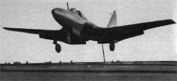
The first prototype McDonnell Phantom during deck-landing trials aboard U.S.S. Franklin D. Roosevelt.
In order to minimise the delay, taxy trials of the first XFD-1, by now named Phantom, began with only one engine installed, and ballast in the other engine bay, during January 1945. Although the 19B engine was producing only 1,325 lb at this stage, the company’s chief test pilot Woodward Burke felt confident enough to allow the aircraft to get airborne on 26 January 1945 in what has subsequently become widely re¬corded as the Phantom’s first flight. According to Kendall Perkins, though, this was only an “initial hop (rising a short way off the ground)”; the first real flight followed a few days later, after the second engine had been installed.
Satisfactory results were recorded in the first few weeks of flight testing, including a speed of 483 mph (778 km/h) at 20,000 ft (6 100 m), an initial rate of climb of 5,000 ft/min (25 m/sec) and a range of 750 mls (1 200 km). Consequently, the Navy was ready to initiate production of its first jet fighter, placing a contract for 100 FD-1s on 7 March 1945. They were to be powered by 1,600 lb st (726 kgp) Westinghouse J30-WE-20 turbojets, these being productionised WE-19s. The pro¬duction aircraft would closely resemble the prototypes, but would have increased internal fuel capacity, provision for a belly drop tank, a taller, square-tipped fin, slightly lengthened front fuselage and (on all but the first three production aircraft) dive brakes in the upper and lower surfaces of the outer wing panels.
Within a few months of production being launched, the war was over, first in Europe and then against Japan. VJ Day, on 2 September 1945, brought massive and immediate cuts in aircraft contracts in the US and that for the FD-1 was cut back to 30 aircraft, but later increased again to 60. Some considera¬tion was given to using an improved Model 19C version of the Westinghouse engine in the second batch of 30 aircraft, perhaps to have been designated FD-2s, but this did not materialise, and the entire production run was of the FD-1 configuration. After a first flight of a production FD-1 on 28 October 1946, deliveries were made from January 1947 to 29 May 1948, with the designation changing from FD-1 to FH-l halfway through the run, on 21 August 1947 (and then becoming retrospective for the Phantoms already in service).
First production aircraft designed by the company, the McDonnell FH-1 Phantom was notable in being also the first jet designed to operate from an aircraft-carrier. The US Navy placed the original letter of intent on 30 August 1943, and the first prototype made its initial flight from St Louis airport, Lambert Field, on 26 January 1945. The type was certainly not over-powered, because the final propulsion system, adopted after many studies of alterna¬tives, was two slim Westinghouse 19B engines buried in the wing roots. Later produced in small numbers as the J30, these were hardly enough for ade¬quate performance.
The first flight is thus all the more remarkable in that, at that time, Westinghouse had been able to deliver only one engine, and one of the wing-root engine bays was empty.
At that time McDonnell’s US Navy designator letter was D, the pro¬totype being the XFD-1, but because of confusion with Douglas (which also used letter D) McDonnell was assigned letter H, so that the 60 pro-duction Phantoms were designated FH-1, first flying on 28 October 1946. They were gentle and easy to fly, and on 21 July 1946 a prototype landed on and took off from USS Franklin D. Roosevelt. The production aircraft were delivered from December 1946 and served mainly with US Marine fighter squadron VMF-122. Their fault was lack of performance and lack of fire¬power, and the next-generation F2H Banshee was a vast improvement on both counts and after equipping one US Navy and two USMC squadrons, were withdrawn in 1950.
FH-1 Phantom Powerplant: two 726-kg (1,600-lb) thrust Westinghouse J30-20 turbojets Maximum speed 771 km/h (479 mph) at sea level / 813 km/h (505 mph) at high altitude Cruising speed 215 kt / 399 km/h Service ceiling 13000 m (43,000 ft) Range 1110 km (690 miles) without belly drop tank. Empty weight 3031 kg (6,683 lb) Maximum take-off weight 5459 kg(12,035 lb) Wing loading 43.67 lb/sq.ft / 213.0 kg/sq.m Wingspan 12.42 m (40 ft 9 in) Length 11.81 m (38 ft9 in) Height 4.32 rn (14 ft2 in) Wing area 25.64 sq.m (276 sq ft) Armament: four 12.7 mm (0.5-in) machine-guns in upper part of nose Crew: 1
The McDonnell F2H Banshee began life even before the end of World War II when the US Navy requested an improved version of the FH-1 Phantom. Designed by a team headed by Herman D. Barkley, bearing a resemblance to the earlier type, the Banshee was of increased size, incorporating folding wings, and with a lengthened fuselage to house more fuel, and with similarly-mounted and more powerful Westinghouse turbojet engines. Conventional ailerons, elevators and rudder were fitted, and split trailing-edge flaps. Small air-brakes were in the top surface of the outer wings. A tricycle undercarriage, with a single wheel on each unit, has the mains retract outward into the wings, and the nose wheel retracts rearward. Fuel was in five tanks in the fuselage.
Three prototypes being ordered on 22 March 1945, as XF2D-1s, these later gaining the name Banshee. First flying in prototype form from St Louis, Missouri, on 11 January 1947, by then redesignated XF2H-1.
Initial trials were successfully accomplished, McDonnell being rewarded in May 1947 by a contract for 56 production F2H-l fighters, which began to enter service with VF-171 of the Atlantic Fleet during March 1949.
Like the later Phantom II, the Banshee proved to be a versatile machine, satisfactorily undertaking day and night fighter tasks, all-weather interception, close air support and photographic reconnaissance.
Following on from the original F2H-1 came the F2H-2, which had slightly more powerful engines and a longer fuselage. Production of the basic F2H-2 totalled 364, some of which were later modified to F2H-2B standard for close support tasks.
F2H-2 Banshee
14 examples of the F2H-2N specialized night-fighter derivative were also completed, these incorporating airborne interception radar in a slightly longer nose.
For reconnaissance, 89 F2H-2P aircraft were completed as new, these being unarmed and featuring six cameras in an elongated nose section.
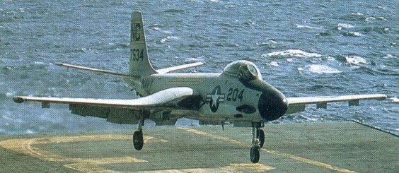
Production then switched to the F2H-3 (in 1962 redesignated F-2C), which was optimized for all-weather fighter duties, the first of 250 entering service during April 1952 and being easily recognizable by virtue of a fusel¬age- rather than fin-mounted tailplane, and was 8 ft longer than the -2, with more than double the internal fuel capacity and APQ-41 radar in the nose (250 built).
During the summer of 1949 the first US pilot to ever use an ejection seat escaped his F2H-1 Banshee while speeding over coastal South Carolina at 500 kts.
From November 1955, 39 ex-US Navy F2H-3s were transferred to the Royal Canadian Navy. That service’s first operational jet fighters, they were operated from HMCS Bonaventure until 12 September 1962, when the last examples were retired from service. They proved to be the last carrier-based fighters in Canadian service. Plans to acquire the F2H-3P for reconnaissance were abandoned.
The final production model was the F2H-4 (F-2D), which introduced improved APG-41 radar and more powerful engines, the 150th and last bringing production of the ‘Banjo’ to a close in August 1953.
The F2H was finally phased out of front line US Navy use on 30 September 1959, but remained with reserve units until the mid-‘sixties.
Contracts were to call eventually for a total of 892 production aircraft.
XF2D-1 / XF2H-1 Engines: 2 x Westinghouse J34 turbojets Number produced: 3
F2H-1 Banshee Engines: 2 x Westinghouse J34-WE-22 turbojets, 3000 lbs.st. Length 40 ft 2 in Armament: 4 x 20 mm cannon. Number produced: 56
F2H-2 Banshee Engines: 2 x Westinghouse J34-WE-34 turbojets, 3250 lbs.st. Length 40 ft 2 in Armament: 4 x 20 mm cannon. Number produced: 364
F2H-2B Banshee Engines: 2 x Westinghouse J34-WE-22 turbojets, 3000 lbs.st. Length 40 ft 2 in Armament: 4 x 20 mm cannon, 2 x 500 lb bomb.
F2H-2N Length 40 ft 2 in Number produced: 14
F2H-2P Banshee Armament: none Number produced: 89
F2H-3 / F-2C Engines: two 14.45kN (3,250-lb) thrust Westinghouse J34-WE-34 turbojets Maximum speed 933 km/h (580 mph) at sea level Service ceiling 14874 m (48,800 ft) Max range 2374 km(1,475 miles) Maximum speed 35,000 ft / 10,668 m: 532 mph / 856 kph Empty weight 55056 kg (11,461 lb) Maximum take-off 7802 kg (17,200 lb) Wingspan 12.73 m (41 ft 9 in) Length 14.68 m (48 ft 2 in) Height 4.42 m (l4 ft 6 in) Wing area 27.31 sq.m (294 sq.ft) Armament: four 20-mm cannon, plus (Canadian aircraft only) two AIM-9 Sidewinder air-to-air missiles. Crew: 1 Number produced: 250
F2H-4 / F-2D Engines: 2 x Westinghouse J34-WE-38 turbojets, 3600 lbs.st. Wingspan: 44 ft. 11 in Length: 47 ft. 6 in Loaded weight: approx. 19,000 lb Max speed: 610 m.p.h Ceiling: 56,000 ft Typical range: 2,000 miles at over 500 mph Armament: 4 x 20 mm. cannon Crew: 1
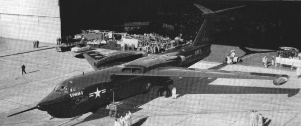
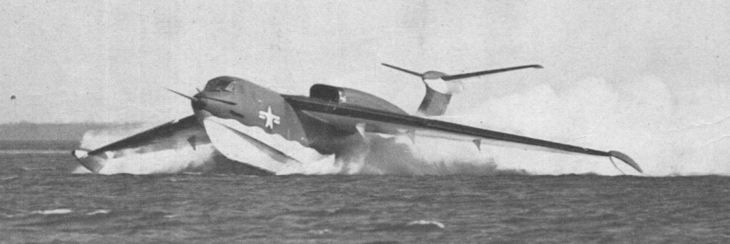
To meet a US Navy requirement for a high-performance multi-role flying-boat, Martin offered its Model 275 design. This had an all-metal hull of high length/beam ratio, mounting a cantilever high-set sharply-swept wing incorporating so much anhedral that the stabilising floats at the wing-tips could be attached permanently; the tail unit was of T-tail configuration with all-swept surfaces. Above the wing, to minimise spray ingestion, were mounted four Allison turbojet engines, and pressurised accommodation was provided for a crew of five. A beaching cradle allowed the SeaMaster to taxi in and out of the water under its own power. The P6M used a rotary bomb bay (as used on Martin’s licence-built Canberras and the XB-51). This permitted weapons release at high speeds without the drag of conventional bomb doors.
The first XP6M-1 prototype was flown on 14 July 1955, the second following on 18 May 1956. Ejection seats were fitted to the second and subsequent aircraft. These proved useful when the second SeaMaster pitched up, went into a loop and disintegrated. The original position of the engine exhausts caused stress on the rear fuselage which resulted in structural damage. The angle of the exhausts was adjusted after testing.
Martin received orders for six pre-production YP6M-1 boats powered by Allison J71 turbojets each developing a maximum 5897kg afterburning thrust. Successful flight testing led to an order for 24 production P6M-2 aircraft named SeaMaster, which differed primarily by having 7711kg thrust non-afterburning Pratt & Whitney J75-P-2 turbojet engines. The cockpit glazing was modified on later models to give a much better overhead and side view. However, the contract was cancelled on 21 August 1959 after only three had been built and these, together with the YP6M-1s, were scrapped at a later date. They were the fastest flying-boats ever built.
YP6M-1 Engines: 4 x J71 turbojet. Speed: 600 mph.
P6M Engines: 4 x Pratt & Whitney J75-P-2 turbojets, 7938kg Wingspan: 30.48 m / 100 ft 0 in Length: 40.84 m / 133 ft 12 in Height: 9.45 m / 31 ft 0 in Max take-off weight: 72575 kg / 160001 lb Payload: 13600kg / 29983 lb Max. speed: 965 km/h / 600 mph Ceiling: 12200 m / 40050 ft Range: 4830 km / 3001 miles Armament: 6 x 12.7mm machine-guns, 1800kg of weapons Crew: 4
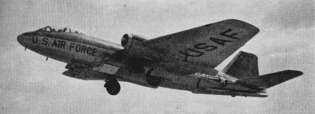
The beginning of the Korean conflict on 25 June 1950 and the shortcomings of the Douglas B-26 / A-26, accounted for the urgent procurement of a light tactical bomber.
The new bomber had to be capable of operating from unimproved airfields, at night and in every kind of weather, with conventional or atomic weapons. High altitude reconnaissance was another must. For such purposes, the B-45 was too heavy; the Navy AJ-1, too slow; and the Martin experimental B-51’s range too short.
As a result of the outbreak in Korea, the Air Force reached a final decision. The desire for a night intruder was so strong that it took just a few days to set in motion the informal production endorsement of February 1951. Because of its experience with the XB-51, the Glenn L. Martin Company was recognized as the most qualified contractor to assume the domestic production of the British aircraft and to deal with the likely engineering difficulties involved in manufacturing a high-performance tactical bomber.
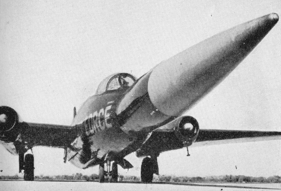
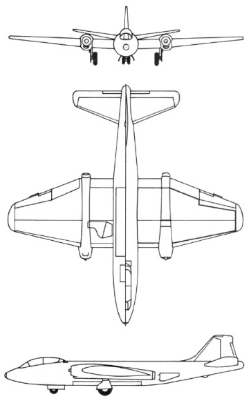
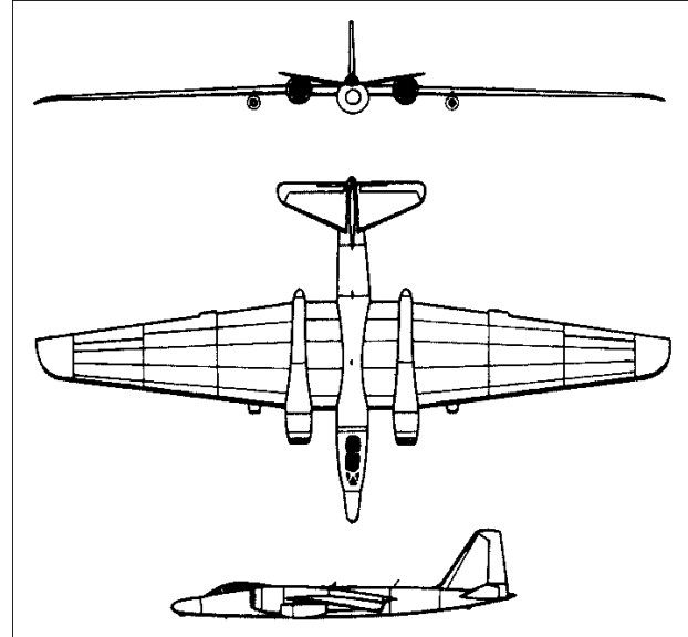
The new bomber became the Martin B-57, a by-product of the English Electric Canberra, the first British-built jet bomber, initially flown in 1949. Adaptation of a foreign-made aircraft to American mass production methods, as well as the use of different materials and tools, could present many difficulties. Another problem, perhaps more critical, centered on the Wright J65 turbojets, due to replace the Canberra’s two Rolls Royce Avon turbojet engines. The J65 was the U.S. version of the Sapphire, a British hand-tooled production currently scheduled for manufacturing by the U.S. Curtiss-Wright Corporation. The Air Force was fully aware of these potential pitfalls, but had no better option. It had an immediate requirement for a light jet bomber, with a 40,000-foot service ceiling, a 1,000-nautical mile range, and a maximum speed of 550 knots.
Testing of two imported Canberras revealed design faults that could affect the safety, utility, and maintenance of the future B-57. Then, one of the British planes crashed; Martin’s subcontractors could not meet their commitments; and the J65 prototype engines consistently failed to satisfy USAF requirements. In June 1952, further test flights had to be postponed for a year because of continuing engine and cockpit troubles. As a result, the Korea-bound B-57 did not fly before 20 July 1953, just 7 days before the conflict ended. Production of the crucial RB-57 was also delayed. The reconnaissance version entered service in mid-1954, after testing again confirmed that the more powerful J65 engines, added equipment, and other improvements had increased the aircraft’s weight, in turn reducing the speed, distance, and altitude of both the B-57 and the RB-57.
The program was reduced, but there was no talk of cancellation. In 1955, the B/RB-57s justified their costs when they served overseas pending the B/RB-66 deliveries which, as predicted, had fallen behind schedule. The first Martin B‑57A (the name Canberra was retained, though Night Intruder was also used) flew on 20 July 1953. In 1956, much-needed RB-57Ds joined the Strategic Air Command, and various configurations of this model satisfied important special purposes.
RB-57D
The main model (202 built) was the B 57B with a redesigned forward fuselage with a crew of only two seated in tandem under a giant rear hinged canopy. This attack version introduced a heavier bombload in a rotary door weapon bay, plus eight pylons under the outer wings and forward firing guns. The B 57B equipped two wings in Tactical Air Command and a wing of PACAF (Pacific Air Forces) but had mainly been passed to Air National Guard units by the early 1960s. Vietnam requirements then demanded aircraft in this class and all available B 57Bs (many had been re built into other models) were rushed to South Vietnam and used very success¬fully in the attack role and in particular as FAC (Forward Air Control) aircraft.
Martin B-57B
Delivered too late for combat in Korea, the RB-57 in May 1963 and the B-57 in February 1965 began to demonstrate under fire in Southeast Asia the basic qualities justifying the Canberra’s original selection.
The original B-57A differed little externally from the English Canberra B2. The RB-57A was similar, with reconnaissance equipment.
The B-57B, with eight 0.50 in or four 20mm guns in the wings, bombs in an internal bomb bay, and underwing racks, served with the Chinese Nationalist and Pakistani air forces.
Variants include the RB-57D(A) and (B) with cameras, the RB-57D(C) and (D) electronics reconnaissance aircraft with radomes at the nose and tail and under the fuselage, and the RB-57(C) with wingtip radomes.
In 1970, other reactivated and newly equipped B-57s, known as Tropic Moon III B-57Gs, were deployed to Southeast Asia, where they made valuable contributions until April 1972. A total of 16 B 57Bs was rebuilt as B-57G (Tropic Moon) all weather and night attack aircraft with APQ 139 radar, a FLIR (forward looking infra-red), low light TV and laser ranger. The most capable aircraft of its day, the B 57G remained a mere study programme despite brilliant combat results.
B-57E
The last new-built version was the B 57E multi role attack/bomber and target tug, all 68 of which were later modified for other tasks.
Martin B-57 modified to test the Boeing Bomarc interceptor missile
Finally, WB-57Fs, either modified RB-57Fs or former B-57Bs, were still flying high-altitude radiation sampling missions in 1973. Concurrently, EB-57Es, and related adaptations of the versatile B-57, continued to play significant roles, with no immediate phaseout in sight.
RB-57F
403 were built under licence by Martin (in six variants) as the B-57 and served with the US Air Force from August 1953 until 1982 in various marks and guises. At a later date a number of these were converted by General Dynamics to serve as ultra high-altitude strategic reconnaissance aircraft. These were provided with a wing span of 37.19m, two 80kN Pratt & Whitney TF33-P-11 turbofan engines (replacing the conventional power plant), plus two 14.68kN Pratt & Whitney J60-P-9 turbojets in underwing pods, and many equipment and avionics changes to fit them for their specialised role. The B-57 saw combat over Vietnam beside other Canberras from Australia.
The USAF bought 21 WB-57F aircraft, which were built by General Dynamics from existing B-57Bs and RB-57Ds. The airplanes’ ability to reach altitudes over 65,000 feet, carry payloads in excess of 4,000 lbs, and its triple spar wings made it a very capable high-altitude platform. Missions included everything from weather reconnaissance for Apollo space launches to sampling radiation in nuclear weapon test plumes.
In the late 1960s and early 1970s the Air Force decided to ground the WB-57F and depend exclusively on the U-2 for high-altitude support. The mission of monitoring nuclear test bans was better done by the WB-57F than the U-2, however. That mission was important enough that three aircraft were given to NASA to keep that capability alive, which were designated N925N, N926NA, and N928NA.
When N925N was retired and put on display at Pima Air & Space Museum in Tucson, Arizona, it that left NASA with two WB-57Fs. Another airframe joined the fleet in 2011 after been taken out of the 309th Aerospace Maintenance and Regeneration Group, (AMARG), better known as the “Bone Yard,” at Davis-Monthan Air Force Base, Arizona. The aircraft, designated N927NA, began as a B-57B, and then was one of 21 aircraft rebuilt as an RB-57F in 1964. As an RB-57F the aircraft had its wingspan increased to 122 feet and the original Wright J65 turbojets were replaced by Pratt & Whitney TF-33 turbofans, doubling both the wingspan and thrust.
N927 had been retired in June 1972 and remained on “celebrity row” at the Bone Yard until May 2011 when it was dismantled and trucked to Sierra Nevada Corporation at Centennial Airport, Colorado. After being refurbished to flying condition it was flown to Ellington AFB in August 2013.
The aircraft had been in storage for over 40 years and made its first flight in 41 years in the summer of 2013, setting a record for the longest an aircraft had sat in the Bone Yard before returning to flying status.
NASA’s WB-57F
Based at Ellington Field near NASA’s Johnson Space Center in Houston, Texas, the WB-57F operates in NASA’s High Altitude Research Program. The aircraft provides unique, high-altitude (up to 70,000 feet MSL) airborne platforms to United States government agencies and other customers for scientific research, advanced technology development, and testing around the world.
Since 2000, the unique performance capabilities of the WB-57F aircraft and increasing costs associated with the ER-2 program have resulted in NASA allowing multiple customers to use the WB-57Fs for atmospheric and satellite sensor research. The DOD programs have gotten much broader, and N928 (and sometimes N926) have multiple customers asking us to help them develop satellite sensors.
Both aircraft were enjoying multiple customers. By June 2014, both aircraft were upgraded with global positioning satellite navigation systems, F-15 main landing gear and brakes, and the gross weight capability of both aircraft was certified from 63,000 pounds to 72,000 pounds. Ongoing upgrades to the aircraft include installation of the ACES II ejection seat system and installation of an improved, modern autopilot.
B-57B Night intruder bomber Engines: 2 x Wright J65-W-3 Sapphire turbojets, 7,500lb thrust Wingspan: 64 ft Length: 65 ft. 6 in Loaded weight: 46,000 lb. Max speed: over 600 m.p.h. Ceiling: over 45,000 ft. Max range: 3,000 miles. Armament: 8x.50 in. machine-guns Bombload: 6,000 lb; 8×5-in. rockets Hardpoints: 4 Crew: 2
B 57B Engines: two 3,275 kg (7,220 lb) thrust Wright J65 W 5 turbojets. Maximum speed 937 km/h (582 mph) at 12190 m (40,000 ft). Service ceiling 14630 m (48,000 ft). Range 3700 km (2,300 miles). Weights: empty 11793 kg (26,000 lb) Maximum take off 24948 kg (55,000 lb) Wing span 19.51 m (64 ft 0 in) Length 19.96 m (65 ft 6 in) Height: 4.75 m (15 ft 7 in) Wing area: 89.18 m (960 sq ft). Armament: eight 12.7 mm (0, 5 in) or four 20 mm guns; up to 2722 kg (6,000 lb), 16 underwing rockets or mixed rocket/ bomb/napalm loads.
RB-57D Engines: 2 x Pratt & Whitney J57C, 11,000 lb Wingspan: 106 ft Length: 65 ft 6 in Height: 14 ft 10 in Max speed: 632 mph at 40,000 ft Service ceiling: 60,000 ft
RB 57F Engines: 2 x Pratt & Whitney TF33 P 11 turbofan, 18,000 lb (8,165 kg) st, and 2 x P&W J60 P 9 auxiliary turbojets, 3,300 lb (1,500 kg) st. Wing span: 122 ft 5 in (37.32 m) Length: 69 ft 0 in (21.03 m). Height: 5.8 m / 19 ft 0 in Max take-off weight: 20360 kg / 44886 lb Empty weight: 13600 kg / 29983 lb Max. speed: 880 km/h / 547 mph Ceiling: 25000 m / 82000 ft Range w/max.fuel: 6440 km / 4002 miles Typical endurance: Over 10 hr Crew: 2 Armament: None