Republic F-105 Thunderchief

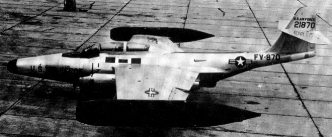
In 1951 Republic began private venture develop¬ment of a single seat tactical fighter bomber which the company anticipated would be a successor to the F 84F Thunderstreak. The F-105 Thunderchief, or company model AP-63. Alexander Kartveli’s design team originally intended a straight fuselage for the craft but, after seeing NACA data assembled by Richard Whitcomb, was won over by the wasp-waist or ‘area rule’ configuration which enhanced transonic flight performance. At first intended for the Allison J71 engine and powered in prototype form by the Pratt & Whitney J57, the F-105 attained its successes with the 7802kg thrust Pratt & Whitney J75-P-19W turbojet which provided 11113kg thrust with afterburning. Its mid-mounted wing, swept 60 degrees, and the F-105 stood high on its tricycle gear.

Republic F-105 Thunderchief Article

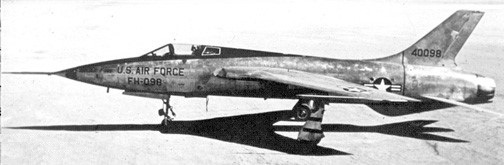
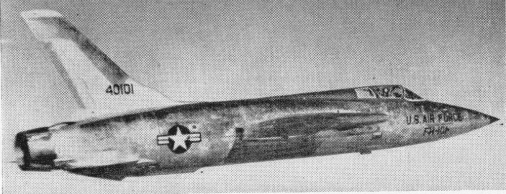
Development began when two J57-powered YF-105As commenced flying 22 October 1955, soon followed by 15 aircraft designated JF-105B and F-105B for test programmes.

The two 1955 YF-105A, 54-0098 and 54-0099, were service testers with 15000 lb P&W J57 engines. The first flew on 22 October 1955, piloted by Russell M Roth.

Republic YF-105A 54-0098

The F-105A was not built in favour of the F-105B. Three RF-105A photo-recon version were built in 1956.

F-105B

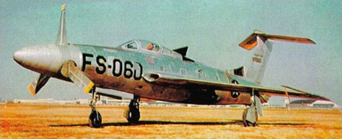
Production F-105Bs, long delayed by development problems, began to roll from Republic’s Farmingdale line during 1958 and the USAF accepted its first machine on 27 May 1958. The 335th Tactical Fighter Squadron, temporarily moved to Eglin AFB, Florida, began to work up in the new aircraft only to find that, given its complexity and production slippages, it would not become operational until 1960. Meanwhile, a two-seat strike variant, the F-105C, had reached the mock-up stage but was not built.

December 1960

Though technical problems persisted and critics were calling the ‘Thud’ a maintenance nightmare, Republic proceeded with the F-105D variant which afforded true, all-weather capability by introducing General Electric FC-5 fully integrated automatic flight fire-control system.

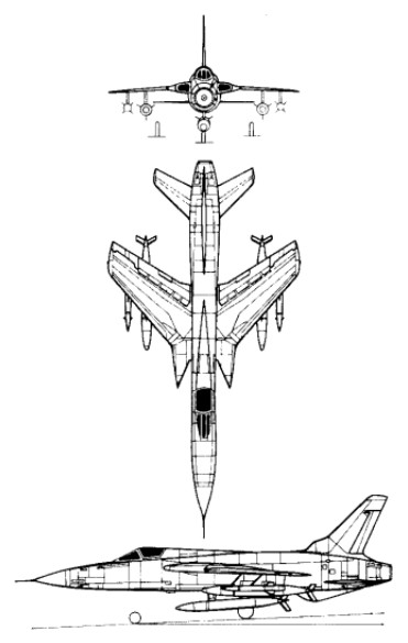
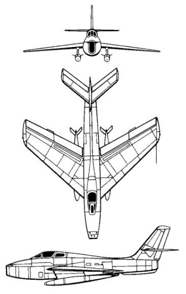
The F-105 has mid-set sweptback wings, sweptback tail surfaces, and a one-piece all-moving tailplane mounted low on the fuselage and with a ventral stabilising fin. The ailerons are used only at low speeds and the main roll control is by five section spoilers forward of the large slotted flaps on each wing. The leading edge is variable-camber. ‘Clover-leaf’ air brake is around the exhaust nozzle. Each undercarriage leg has a single wheel, the mains retracting into the wings and nose wheel retracting forward.

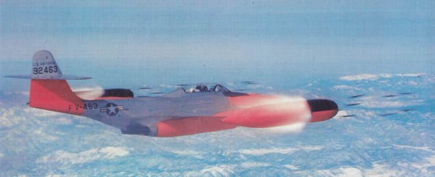
The F 105D was powered by a Pratt & Whitney J75 P 19W turbojet engine that develops 26,500 lb thrust (with after¬burning). The F-105D’s fuselage was lengthened by 0.381m. Some 610 were manufactured, and first flight took place at Farmingdale 9 June 1959. The F-105D model soon equipped all three squadrons of the 4th Tactical Fighter Wing at Seymour Johnson AFB, North Carolina. United States Air Forces in Europe (USAFE) were the first overseas recipient of the F-105D, the 36th TFW at Bitburg AB, West Germany re-equipping from 12 May 1961 and the 49th TFW at Spangdahlem soon following. In the early 1960s, with a war growing in Asia, F-105Ds joined the 18th TFW at Kadena AFB, Okinawa.

F-105D

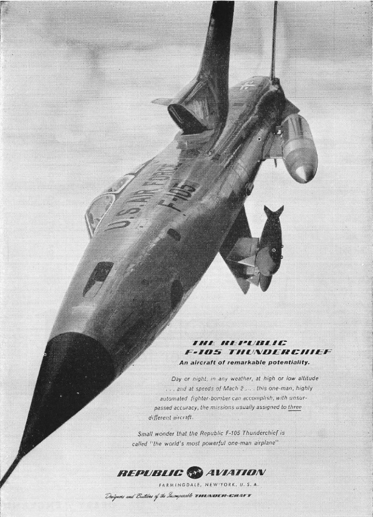
The F-105D was by now a proven ordnance-carrier. More than 14,000 lb (6,350 kg) of weapons can be carried on under fuselage/wing stations. An internal weapons bay was also provided, and both conventional and nuclear weapons can be deployed. With multiple ejector racks (MER), it could carry an impressive load of external fuel, ECM gear, and eight 340kg bombs on long-range missions. The F-105D could also operate with the Martin AGM-12 Bullpup air-to-surface missile, which was to prove remarkably ineffective against ‘hard’ targets in Vietnam and would be observed bouncing off the Thanh Hoa Bridge. In addition, the F-105D model could carry 70mm rocket pods, napalm canisters and the AIM-9 infra-red (IR) air-to-air missiles, while its integral M61A1 Gatling-type 20-mm cannon proved invaluable in the dual roles of air-to-air combat and air-to-ground strafing. A late-model variant of the F-105D was the F-105D T-Stick II fitted with additional avionics which bestowed all-weather bombing capability, housed in a prominent dorsal fairing extending along the spine of the fuselage to the tail.

The F-105E was another two-seat variant that was not developed.

In May 1962 Republic proceeded with the tandem two seat F-105F. The first aircraft of this type (62 4412), which made its first flight 11 June 1963, was some 900kg heavier as well as slightly longer than earlier Thunderchiefs in order to accommodate the second crewman in tandem. The second F 105F, which flew for the first time on July 25 1963, flew thirty seven demonstration flights from Andrews AFB on August 18th, turn¬around being consistently completed within twenty minutes. The performance of the two seat F 105F is within 3% of the single-seat F-105D.

The two seat F 105G, developed from the F 105F combat/trainer version, carries advanced ‘Wild Weasel’ equipment to detect emissions from enemy radar sites, controlling surface-¬to air missiles, and missiles which can destroy the sites.

143 F-105Fs were delivered and 61 were later reconfigured for the electronic warfare or ‘Wild Weasel’ role in Vietnam, at first under their original designation and later as the F-105G.

After cancelling all airshows for two big summer months the Airforce Thunderbirds reverted back into F-100s in August 1965 to complete the season. They had started in Republic F-105s but a series of accidents throughout the Air Force grounded all Thunderchiefs.

Thunderbird F-105s

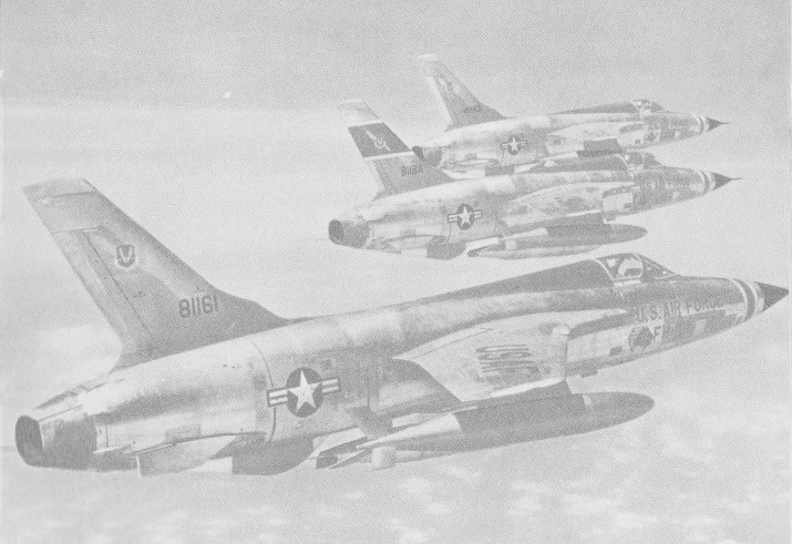
The F-105D, F-105F and F-105G all fought in North Vietnamese skies, the F-104D model fighter-bomber so extensively that over half of the 610 built eventually fell to Hanoi’s air defences. After withdrawal from South East Asia in 1969-70, the Thunderchief soldiered on in Reserve and Air National Guard units, eventually flying its final sortie in 1984. At one time no fewer than 14 USAF and 11 ANG squadrons operated the type, which was built to the extent of 833 examples. Perhaps because of its complexity, no F-105 was ever exported.

Republic F-105 Experiences

Gallery

F-105B
Engine: 1 x Pratt & Whitney J75-P-5, 25,000 lb
No built: 75

F-105D
Engine: 1 x Pratt & Whitney J75-P-19W, 76.5kN / 26,500 lb reheat
Wingspan: 10.59 m / 35 ft 9 in
Wing area: 35.77 sq.m / 385.02 sq ft
Length: 19.61 m / 64 ft 4 in
Height: 5.97 m / 20 ft 7 in
Max take-off weight: 23967 kg / 52838 lb
Empty weight: 12474 kg / 27501 lb
Fuel capacity: 1000 Imp.Gal
Aux fuel weapons bay: 290 Imp.Gal
Underwing & fuselage fuel: 3 x 375 Imp.Gal
Max. speed: 1208 kt / 2237 km/h / 1420 mph / M2.15 at 36,000 ft
Cruising speed: 508 kt / 940 km/h
Ceiling: 12560 m / 41200 ft
ROC: 34,500 fpm
Range w/max.fuel: 3846 km / 2390 miles
Crew: 1
Armament: 1 x 20mm cannon, M61 Vulcan/1029rds, 6350kg of weapons
Hardpoints: 6
Inflight refuel: yes

Republic F-105 Thunderchief

Republic F-84 Thunderjet / Thunderstreak / RF-84 Thunderflash

Republic F-84B Thunderjet

The first prototype Republic XP-84 made its maiden flight on 28 February 1946, powered by a General Electric J35 engine.

Fifteen YP-84A were built in 1946 for service trials; 45-59482 to 45-59496.

Republic YP-84A 45-50490

Dubbed ‘Thunderjet’, the straight-winged F-84 saw operational service in Korea from December 1950, first as an escort fighter to B-29 bombers and then in the ground attack role. The F-84G was developed to carry nuclear weapons for tactical warfare and was used by TAC and SAC; F-84Gs without nuclear weapon delivery systems were supplied to various NATO air forces and no less than 4,457 straight-wing Thunderjets were built.

F-84E Thunderjet

Although it shared the same generic designation number as the straight-winged F-84 Thunderjet, the Republic F-84F Thunderstreak was essentially a new aircraft. The prototype XF-84F was an F-84E Thunderjet fitted with 40 degree sweptback wing and tail, and longer, faired-in cockpit hood. It was powered by a 5200 lb Allison J-35-A-25 turbojet. When Curtiss-Wright acquired a license to build the Armstrong Siddeley Sapphire turbojet in America, Republic fitted an imported Sapphire in the YF-84F prototype which flew on 14 February 1951. The USAF ordered this aircraft into production, with a Wright-built J65 Sapphire, as the F-84F Thunderstreak.

Republic F-84 Thunderstreak Article

F-84F

The RF-84F served as the backbone of NATO tactical strike forces, operating with Belgium, France, Italy, Greece, the Netherlands, Turkey and West Germany.

Yugoslavian F-84Gs

On 10 March 1953, five days after a Polish pilot had defected with his MiG-15 to the Danish island of Bornholm, two Czechoslovakian MiG attacked two American F-84G Thunderjets over Regensburg in Bavaria. One of the Thunderjets was shot down by the 23mm and 37mm cannon of one of the MiGs. The pilot ejected safely over Czechoslovakian territory.

By 1955 the F-84F Thunderstreak was the standard U.S.A.F. fighter-bomber, replacing F-86 Sabres and F-84E and -G Thunderjets. Can carry the tactical atomic bomb, and can be carried itself by GRB-36 “mother-plane”. Versions carried by GRB-36 have anhedral (downswept) tailplane.

Initially conceived by Republic dating 1949, the Thunderstreak was first flown in prototype form as the YF-84F on 3 June 1950, this aircraft using a standard F-84E fuselage with a swept wing and being powered by a single Allison YJ35-A-25 engine rated at 2359-kg (5,200-lb) thrust. Early flight testing of this aircraft very quickly revealed that the performance left a great deal to be desired and it was therefore decided to incorporate the British Sapphire (Wright J65) engine, impetus for the change being largely provided by US involvement in the Korean War, although in the event the F-84F did not see action in that conflict. Adoption of the more powerful engine in turn necessitated some redesign and it was not until late 1952 that the first production specimen made its maiden flight. Altogether 2,711 F-84Fs were built for service with allied nations from the late 1950s onwards.

F-84F

A specialized photo-reconnaissance derivative of the F-84 known as the RF84F Thunderflash was evolved more or less concurrently, this being most easily recognized by its revised air inlet layout which permitted the battery of cameras to be mounted in the extreme nose section. The RF-84F Thunderflash photo-reconnaissance aircraft had cameras in lengthened nose, only 4 guns, and wing-root air intakes. It too can be carried by GRB-36. The first prototype flew in February 1952. Including the prototype YRF-84F, 716 Thunderflashes were built, almost half of this figure being destined for overseas service under the terms of the Mutual Defense Aid Program, examples being supplied to Italy, Greece, West Germany, Turkey, the Netherlands, Belgium, Denmark, Taiwan, France and Norway.

It has another distinction so far as the USAF is concerned, being the aircraft with which flight refuelling techniques for fighters were developed.

RF-84F

A total of 4457 F-84 “Thunderjet” were built.

The second attempt to use the B 36 as an aircraft carrier took place in 1955 and 1956. Seeking a reconnaissance aircraft with sufficient range to reach the Soviet Union, the USAF came up with FICON, which stood for Fighter In CONvair. By hitching a Republic RF 84 Thunderflash to a B 36, the photo-reconnaissance jet’s range could be extended from 3220 km (2000 miles) to 19,310 km (12,000 miles). Some thought was also given to a nuclear bomb equipped Thunderstreak substituting for the Thunderflash. Twenty five RF 84Fs were modified for parasite duty. On a typical mission the mother ship B 36 would depart from Fairchild Air Force Base, Spokane, Washington to be joined in the air by an RF 84K (as the parasite Thunderflashes were designated) from Moses Lake Air Force Base. The fighter would be hoisted into the B 36’s bomb bay.

F-84G Thunderjet

The F-84G Thunderjet featured conventional ailerons, elevators, rudder and trailing edge flaps. An air-brake is under the centre fuselage. The tricycle undercarriage has a single wheel on each unit, the mains retracting inward into the wings, and nose-wheel retracts rearward.

Even in the mid-1950s the superiority of the jet powerplant for combat aircraft was questioned by some. A modern technology propeller driven by a turbine (a turboprop) offered high speeds, long endurance and low landing speeds. To test this concept the USAF commissioned two XF-84Hs from Republic.

XF-84H

Powered by the Allison XT-40 coupled turboprops driving a singe supersonic blade propellor, the noise the F-84H made has been described as an ‘unholy shriek’, leading to the nickname ‘Thunderscreech’. Resonance off the ground made groundcrew physically sick. The two aircraft only made a dozen test flights, all but two of which resulted in emergency landings and the USAF refused to accept it for their own tests, cancelling the programme in 1956.

The first XF-84H spent 40 years on a pole at Bakersfield Airport, California, its propeller slowly (and quietly) rotated by an electric motor.

Gallery

F-84E Thunderjet
Fighter-bomber
Engine: 5,000 lb. thrust Allison J35-A-17 turbojet.
Wingspan: 37 ft. 5 in
Length: 38 ft. 5 in
Loaded weight: 18,000 lb.
Max. speed: 630 m.p.h.
Ceiling: over 45,000 ft
Normal range: 1,700 miles
In flight refueling: yes
Armament: 6x.50 in. machine-guns
Bombload: 4 x 1,000 lb. bombs or up to 32 x 5 in. rockets.
Crew: 1

Republic F-84F Thunderstreak
Type: single-seat strike fighter
Powerplant: one 3275-kg (7,220-lb) thrust Wright J65-W-3 turbojet
Maximum speed 1118 km/h (695 mph) at sea level
Initial climb rate 2499 m (8,200 ft) per minute
Service ceiling 14020 m (46,000 ft)
Combat radius, clean 724 km (450 miles)
Ferry range 3444 km (2,140 miles)
Maximum take-off 12701 kg (28,000 lb)
Wingspan 10.26 m (33 ft 7¼ in)
Length 13.23 m (43 ft 4¾ in)
Height 4.39 m(14 ft4¾ in)
Wing area 30.19 sq.m (325 sq ft)
Armament: six 12.7-mm (0.5-in) M3 machine-guns
Bomb load, 2722 kg (6,000 lb)
Crew: 1

RF-84F Thunderflash
Engine: Wright J65-W-7, 7800 lb
Wingspan: 33 ft 7 in
Length: 47 ft 7.75 in
Height: 15 ft
Max speed: 679 mph at SL
Max ROC: 8000 fpm
Service ceiling: 46,000 ft
Max range: 2200 mi
Armament: 4 x .50 in mg

F-84G Thunderjet
Engine: 1 x Allison J35-A-29, 24.9kN / 5600 lb
Wingspan: 11.4 m / 37 ft 5 in
Length: 11.7 m / 38 ft 5 in
Height: 3.8 m / 12 ft 6 in
Wing area: 24.2 sq.m / 260.49 sq ft
Wheel track: 16 ft 6 in
Max take-off weight: 8455-10670 kg / 18640 – 23523 lb
Empty weight: 5033 kg / 11096 lb
Max. speed: 970 km/h / 603 mph
Cruise speed: 775 km/h / 482 mph
Ceiling: 12350 m / 40500 ft
Range w/max.fuel: 1680 km / 1044 miles
Armament: 6 x 12.7mm machine-guns
Bombload: 4500 lb
Crew: 1

XF-84H
Engine: 1 x 5850 hp Allison XT40-A-1 turboprop
Wingspan: 10.18 m / 33 ft 5 in
Length: 15.67 m / 51 ft 5 in
Height: 4.67 m / 15 ft 4 in
Max take-off weight: 8123 kg / 17908 lb
Max. speed: 837 km/h / 520 mph
Crew: 1

Republic F-84E Thunderjet
Republic F-84F Thunderstreak
RF-84F Thunderflash

Pratt & Whitney J58 / JT11D

J58

The Pratt & Whitney J58 (company designation JT11D) was a jet engine used on the Lockheed A-12, and subsequently on the YF-12 and SR-71 aircraft. The J58 was a single-spool turbojet engine with an afterburner.

The J58 was initially developed for the US Navy to power the planned version of the Martin P6M jet flying boat. Upon cancellation of this aircraft, it was selected by Convair and Lockheed for their supersonic projects. Other sources link its origin to the USAF’s requirement for a powerplant for the WS-110A, the future XB-70 Valkyrie. The J-58 produced 32,000 lbf (142 kN) of thrust. It was the first engine to be able to operate on afterburner for extended periods of time, and the first engine to be flight-qualified by the United States Air Force for Mach 3. A major feature of the J58 installation were the conical spikes in the variable-geometry inlets, which automatically moved fore and aft, controlled by an Air Inlet Computer. The spike altered the flow of supersonic air, ensuring good pressure recovery and minimum distortion at the engine inlet. The conical spikes are locked in the forward position below 30,000 feet and un-locked above that altitude. Above Mach 1.6 they are retracted approximately 1⅝ inch (4 cm) per Mach 0.1, up to total of about 26 inches (66 cm).

A variety of engine starting operations were available throughout the life of the A-12, F-12 and SR-71 aircraft, including: A twin chamber mono-fuel starter, attached to the engine only for starting, an AG330 starter cart, with two Buick Wildcat V8 internal combustion engines driving a common output, spinning the J58 to 3,200 rpm before the turbojet could self-sustain.

The engine’s high operating speeds and temperatures required a new jet fuel, JP-7. Its reluctance to be ignited required triethylborane (TEB) to be injected into the engine to ignite it, and to ignite the afterburner in flight; above -5 °C TEB spontaneously ignites in contact with air. Each engine carried a nitrogen-pressurized sealed tank with 600 cm3 (20.7 ounces) of TEB, sufficient for at least 16 starts, restarts, or afterburner lights; this number was one of the limiting factors of SR-71 endurance, as after each air refueling the afterburners had to be reignited. When the pilot moved the throttle from cut-off to idle position, fuel flowed into the engine, and shortly afterwards an approx. 50 cm3 (1.7 ounce) shot of TEB was injected into the combustion chamber, where it spontaneously ignited and lit the fuel with a green flash. In some conditions, however, the TEB flow was obstructed by coking deposits on the injector nozzle, hindering restart attempts. Refilling the TEB tank was a perilous task; the maintenance crew wore silver fire suits. Conversely, the JP-7 fueling was so safe that some aircraft maintenance was permitted during filling. The chemical ignition was chosen instead of a conventional igniter for reliability reasons, and to reduce mechanical complexity. The TEB tank is cooled with fuel flowing around it, and contains a disk that ruptures in case of overpressure, allowing TEB and nitrogen to discharge into the afterburner.

The fuel flowing into the engine is used as a coolant to cool the engine, hydraulic fluid, oil, TEB tank, afterburner nozzle actuator control lines, air conditioning systems, and the parts of the airframe subjected to aerodynamic heating.

The engine lubricant was a silicone-based grease. It was solid at room temperature, and was preheated prior to engine start.

Jet engines take in their air at about Mach 0.4 irrespective of their flight speed, whether it be zero or Mach 3. Efficient operation of the engine inlet requires that it delivers the air to the engine at that speed. The Lockheed Blackbird family of aircraft was designed to travel at speeds over Mach 3.2 and the slowing down of the air from this high speed to about Mach 0.4 was controlled by the intake shock cone and the shape of the downstream internal ducting(both were part of the airframe and designed by Lockheed). As air slows down, its temperature rises (to nearly 400 deg C at a flight speed of Mach 3.2) and it was this high temperature entering the compressor that prevented the J58, as originally designed, from powering the Blackbirds to Mach 3.2. This section describes how the compressor was modified for Mach 3.2 flight to handle the aerodynamic effects of high inlet temperature. The section is based on information in U.S.Patent 3,344,606 and the SR-71 Flight Manual.

The patent summarizes why the J58 would not work at Mach 3.2 – “As a result of the ram air temperature rise the thrust output drops because of insufficient airflow, compressor tolerance to surge (or compressor stall) is poor, and low compressor efficiency occurs resulting in high fuel consumption. Also the compressor blades are subjected to high stress from the combination of high rotational speed and flutter from rotating stall in the front stages”.

It specifies the object of the invention – “to improve the thrust generating quality of a turbojet engine with afterburner during high supersonic flight speed operation and to improve the compressor efficiency, the compressor surge margin and the compressor blade and vane fatigue problem”.

It summarizes the solution – “.. by bleeding a portion of the compressor air from an intermediate compressor stage and recovering the air in the afterburner for reheating therein prior to discharge to atmosphere with the remainder of the exhaust gasses”.

It was found that 20% of the engine flow needed to be bled from the fourth stage to combat the effects of high compressor inlet temperature and to restore the operation of the compressor to an acceptably high efficiency and flow capacity when operating at Mach 3.2.

The bleed air was returned to the engine to provide both cooling for the afterburner liner and more air for afterburner combustion. It passed through six external tubes from the compressor to the afterburner.

The SR-71 Flight Manual provides information on the use of the bleed (“bleed and IGV shift schedule”) in terms of engine RPM and Mach number or compressor inlet temperature. It shows that this air bleed, which it calls internal, is also necessary, together with an extra bleed, which it calls external, during starting and low engine RPM.

The schedule shows that variable inlet guide vanes (IGV) were also part of the compressor design. Unlike most variable IGV, where the whole vane pivots, the J58 vanes had 2-position, part-span trailing edge flaps only.

Like the bleed flow the position of the flaps was also determined by the engine speed and compressor inlet temperature.

A schematic view of the engine is also shown on the schedule showing the engine bleed air path from the compressor to the afterburner.

The final configuration of the J58 for Mach 3.2 flight was that of a “turbojet with bleed air recovery”, as stated in the patent. An alternative classification was a “turbojet with afterburner and compressor bleed bypass at high Mach”, as stated in the Flight Manual. The engine designation was JT11-D20.

The propulsion system consisted of the intake, engine, nacelle or secondary airflow and ejector nozzle(propelling nozzle). The propulsive thrust distribution between these components changed with flight speed.
at Mach 2.2 inlet 13% – engine 73% – ejector 14%
at Mach 3.0+ inlet 54% – engine 17.6% – ejector 28.4%

The intake had to supply air to the engine with minimum pressure loss and distortion and at the speed dictated by the engine, namely about Mach 0.4. It had to do this at all flight conditions.

The ejector nozzle, together with the engine variable nozzle, performed the reverse function of the inlet accelerating the turbine exhaust from about Mach 0.4 back up to Mach 3. Mach 3 exhaust velocity is higher than Mach 3 flight velocity due to the much higher temperature in the exhaust. The nacelle airflow from the intake controlled the expansion of the hot engine exhaust in the ejector nozzle. This air flowed around the engine and served also to cool the hot external parts of the engine and to purge any combustible mixtures in the event of a fuel or oil leak in the nacelle.

Applications:
Lockheed A-12
Lockheed M-21
Lockheed SR-71 Blackbird
Lockheed YF-12

Specification:
J58-P4
Type: afterburning turbojet with compressor bleed bypass
Length: 17 ft 10 in (5.44 m) (an additional 6 in (15 cm) at max. temp.)
Diameter: 4 ft 9 in (1.45 m)
Dry weight: approx. 6,000 lb (2,700 kg)
Compressor: 9-stage, axial flow, single spool
Combustors: 8 can, annular
Turbine: two-stage axial flow
Fuel type: JP-7
Maximum thrust: 34,000 pounds-force (150 kN) (wet), 25,000 pounds-force (110 kN) (dry)
Overall pressure ratio: 6
Specific fuel consumption: 1.9 lb/(lbf-h) (wet), 0.9 lb/(lbf-h) (dry)
Thrust-to-weight ratio: approx. 6
Core air flow: 450 lb/s, (200 kg/s)

Pratt & Whitney J75 / JT4A

Part of a Pratt & Whitney J75 from a downed Lockheed U-2 in Cuba

The Pratt & Whitney J75 (company designation: JT4A) was an axial-flow turbojet engine first flown in 1955. A two-spool design in the 17,000 lbf (76 kN) thrust class, the J75 was essentially the bigger brother of the Pratt & Whitney J57 (JT3C). It was known in civilian service as the JT4A, and in a variety of stationary roles as the GG4 and FT4.

In military use, the J75 was used on the Lockheed U-2, the Republic F-105 Thunderchief, and the Convair F-106 Delta Dart. It was also utilized in the prototype and experimental Lockheed A-12, North American YF-107, Vought XF8U-3 Crusader III, Martin P6M SeaMaster, and Avro Canada CF-105 Arrow.

Before the arrival of the Pratt & Whitney JT3D turbofan engine, the JT4A was used to power certain Boeing 707 and Douglas DC-8 models, bringing improved field performance in the medium-range Boeing 707-220 and Douglas DC-8-20, and intercontinental range in the Boeing 707-320 and the Douglas DC-8-30.

After its relatively short lifetime in the aircraft role, the JT4A found more enduring use in the naval role, where the FT4 was produced in a variety of models between 18,000 and 22,000 hp. Well-known uses include the first all-turbine warships, the Canadian Iroquois class destroyers, as well as the United States Coast Guard’s Hamilton class cutters, and it was considered for the US Navy’s Asheville class gunboat. The same basic powerplant saw much wider use as a peak demand power turbine running on natural gas. From its introduction in 1960 over 1,000 FT4s have been sold, with many of them still in operation for electrical generation. Outdated by modern standards, refits were available that add catalytic converters to lower their emissions.

Variants:
J75-P-3
16,470 lbf (73.26 kN) thrust

J75-P-5
17,200 lbf (76.51 kN) thrust

J75-P-13B
17,000 lbf (75.62 kN) thrust

J75-P-15W
24,500 lbf (108.98 kN) afterburning thrust

J75-P-17
24,500 lbf (108.98 kN) afterburning thrust

J75-P-19
24,500 lbf (108.98 kN) afterburning thrust

J75-P-19W
26,500 lbf (117.88 kN) afterburning thrust with water injection

JT4A-3
15,800 lbf (70.28 kN)

JT4A-4
15,800 lbf (70.28 kN)

JT4A-9
16,800 lbf (74.73 kN)

JT4A-11
17,500 lbf (77.84 kN) thrust

JT4A-29
(J75-P-19W) 26,500 lbf (117.88 kN) afterburning thrust with water injection

Applications:

J75
Avro Canada CF-105 Mk1 Arrow
Convair F-106 Delta Dart
Lockheed A-12
Lockheed U-2
Martin P6M SeaMaster
North American F-107
Republic F-105 Thunderchief
Vought XF8U-3 Crusader III

JT4A
Boeing 707 (specifically, the 707-220 and 707-320 sans suffixe)
Douglas DC-8 (specifically, the DC-8-20 and DC-8-30)

Specifications:
J75 / JT4A-3
Type: Turbojet
Length: 144.1 in (3,660 mm)
Diameter: 43 in (1,092 mm)
Dry weight: 5,020 lb (2,277.0 kg)
Compressor: Two-spool axial compressor
Maximum thrust: 15,800 lbf (70.28 kN) at 8,000 rpm
Overall pressure ratio: 12:1
Specific fuel consumption: 0.8 lb/(h·lbf)
Thrust-to-weight ratio: 3.147 lbf/lb (0.308 kN/kg) (maximum thrust/dry weight)

Piasecki PD-22 / H-21 Shawnee / Workhorse / Vertol 42 / H-21 Shawnee

Piasecki H-21

Developed from the US Navy’s HRP-2 Rescuer, the Piasecki PD-22 tandem-rotor helicopter prototype (US Air Force designation XH-21) was first flown on 11 April 1952 with Len LaVassar and Marty Johnson at the controls.

Piasecki PD-22 / H-21 Shawnee Article

Piasecki YH-21

Winner of a USAF competition for an arctic transport helicopter, the new craft looked almost like the HRP-2, but weighed 6630kg fully loaded, more than twice the earlier machine. A 1425hp Wright R-1820 engine (derated in early models to 1150hp) and a 0.9m increase in rotor diameter to 13.4m gave it much better performance than the HRP-2. The H-21 used the single engine with tandem three-blade rotors. Structurally, it was a new aircraft. (TC 1H12, 1H16, H1AL, H3EA, H8WE, H9EA, HR35).

The Work Horse could carry fourteen fully equipped troops or an equivalent weight of cargo. Features included a rescue hoist and inflatable donut-shaped floats around its wheels for landings even on marshy tundra. Winterized to support Distant Early Warning (DEW) Line radar stations far to the north, extensive cold-weather testing was performed atop Mount Washington, the highest peak in New Hampshire’s White Mountains, as well as in the climate hangar at Eglin Air Force Base.

Eighteen Model PD-22 / YH-21 helicopters had been ordered in 1949 for USAF evaluation, these being followed by an initial production batch of 32 H-21A helicopters, named Workhorse in USAF service. For use by the Military Air Transport Service Air Rescue Service, the H-21As were each powered by a derated 932kW Wright R-1820-103 engine; the first flew in October 1953. Six more were built to USAF contract but supplied to Canada under the Military Assistance Program. Vertol produced in 1957 a small number of Vertol Model 42A, exclusively Canadian civil conversion of RCAF H-21B helicopters used to supply stations of the mid-Canada radar chain.

The second production variant was the H-21B, which used the full power of the 1063kW R-1820-103 to cover an increase in maximum take-off weight from 5216kg to 6804kg. The Air Force eventually purchased 163, mainly for Troop Carrier Command, and these had autopilots, could carry external auxiliary fuel tanks, and were provided with some protective armour. They could carry 20 troops in the assault role.

The Army became aware of the H-21’s potential as a medium utility helicopter soon after the type’s maiden flight, and in 1952 awarded Piasecki a contract for the production of the H-21C variant. This aircraft retained the H-21B’s extensive armor plating and ability to carry two external fuel tanks, but had such additional features as increased troop capacity and a 4000-pound capacity belly sling hook. The Army procured 334 H-21C Shawnees, with deliveries beginning in August 1954. In addition, the Army obtained at least sixteen H-21B aircraft from the USAF; the majority of these machines were ultimately brought up to H-21C standard, and all were known as Shawnees despite their origins as Work Horses. The B and C variants of the H-21 were used in Vietnam, equipped with 12.7 or 7.62mm light machine guns which were fired through the cabin doors.

While the Navy’s helicopters had a 600hp Pratt & Whitney R-1340 engine, those for the Army had a Wright R-1820. Thirty-three of the H-21A were assigned to SAR units in the Arctic and another five were sent to Canada. Foreign operators of the H-21 included the German Army (26), French Army (98), French Navy (10), Japanese armed forces (10) and Swedish Navy (11).

The US Army’s equivalent was the H-21C Shawnee, of which 334 were built. This total included 98 for the French army, 10 for the French navy and six for Canada; 32 Shawnees were supplied to West Germany, serving with the army’s Heeresfliegerbataillon 300. The first deliveries to the Army were in September 1954 with production continuing until March 1959. The H-21C, redesignated CH-21C in July 1962, had an underfuselage sling hook for loads of up to 1814kg. Production deliveries were made between September 1954 and March 1959, later helicopters acquiring the company designation Model 43 when the Piasecki Helicopter Corporation became the Vertol Aircraft Corporation in 1956. The H-21 A and H-21B retrospectively became the Model 42. In 1962 the H-21B and H-21C were redesignated as, respectively, the CH-21B and CH-21C.

Two turboshaft conversions of H-21C airframes were the Model 71 (H-21D), with two General Electric T58 engines first flown in September 1957, and the Model 105 which had two Avco Lycoming T53s in 1958. The variant was not adopted for production. From the latter was designed the Vertol 107 (Boeing Vertol H-46 series).

Most Shawnees were withdrawn from the active inventory by 1965.

H-21C

It set a closed-course distance record of 1,199 miles in Aug 1957 with extra fuel tank. It was a Shawnee dubbed ‘Amblin’ Annie that made the first non-stop helicopter flight from one coast of the United States to the other, being refuelled in flight from a U-1A Otter in Aug 1957. More significantly, the H-21 was the first American military helicopter type to be deployed in appreciable numbers to South Vietnam: the first four Shawnee units arrived in that country between December 1961 and September 1962. The H-21 also gained the dubious distinction of being the aircraft in which America’s first Vietnam casualties were killed; four Army aviators died in July 1962 when their Shawnee was shot down near the Laotian-Vietnamese border.

“I was working as a helicopter mechanic with the U.S. Army Aviation Service Test Board in 1954 and 1955 and we received some of the first production H-21Cs for operational testing; I was assigned to serial number 51-15888, tail number 115888, the eighth built, and I recall us having 115881 also which I believe was the one we picked up at Edwards AFB in 1955. The Air Force did all engineering flight testing for the Army and when they completed tests on the H-21C version (in preparation for their USAF H-21B version ordered after the “C”), a small group of us from the Fort Rucker Test Board went to Edwards to take over the ship and perform some high altitude and desert tests before flying back to Rucker. Arriving at Edwards, complete with papers and “secret” clearances, we promptly discovered that the USAF’s Army H-21C was in terrible condition and unairworthy. Much to their dislike and consternation, we hung around the air base for several days while we performed an inspection and changed the Wright 1820 engine – the desert flying had eaten up the cylinders and bearings to the point that the 19-gallon oil tank wouldn’t sustain a single flight! Needless to say, there was some exciting experimental jet activity going on at Edwards at that time and we GIs were in no hurry to leave as we had a front line seat on the test ramp. We spent a few weeks at an Apple Valley dude ranch, parking the helicopter in the desert, and refueling at George AFB. Each day we flew several sorties into the White Bear region and did a few exciting running takeoffs at White Bear Lake. We made an uneventful (mostly), but rather warm and humid, flight back to Rucker, taking a pretty straight course from San Antonio across Texas, Louisiana, Mississippi and into Alabama. A late evening thunderstorm threw us off course during a night flight leg and we made an “off-airport” landing in a drenched high school football stadium in Mississippi (still lit up following a game); the locals fed us and I wound up spending the night RON in a friendly funeral parlor. One of the Board’s test H-21s made the first non-stop flight across the U.S. in August, 1956; it took 37 hours and refueling by a fixed wing”.

Piaski 42

1955 commercial developments of the H-21 included models 42, 43, 44, 63, and 71.

Gallery

YH-21 / PD-22
Engine: 1150hp Wright R-1820-103
Rotors: 44’6″
Length: 86’4″
Max speed: 131 mph
Cruise: 110 mph
Ceiling: 15,000′
Capacity: 14 fully-equipped troops

H-21 Shawnee / CH-21/UH-21
Engine: Wright R-1820-103, 1425hp
Rotor diameter: 44’0″
Length: 52’7″
Useful load: 4500 lb
Max speed: 130 mph
Cruise speed: 98 mph
Range: 265-400 mi
Ceiling: 9,4500 ft
Passenger capacity: 20

H-21A
Engine: 1150hp Wright R-1820-103
Medevac capacity: 12 litter patients

H-21B Work Horse
1957
Engine: 1425hp Wright R-1820-107
Capacity: 20 troops or 12 litters

H-21C
1957
US Army version

H-21D
1957
Engines: 2 x GE T58 gas turbines
First flight: September 1957

Vertol 42A
1954
Length : 52.165 ft / 15.9 m
Height : 15.354 ft / 4.68 m
Rotor diameter : 44.029 ft / 13.42 m
Max. speed : 110 kt / 204 km/h
Service ceiling : 10335 ft / 3150 m

Piasecki PV-14 / PV-18 / HUP Retriever / UH-25

Piasecki set to work on a specification, issued by the US Navy Bureau of Aeronautics in 1945, for a shipboard helicopter to be used on aircraft carriers and larger vessels for SAR, liaison, replenishment and plane guard duties.

Designated PV-14 (XHJP-1 by the US Navy), two XHJP-1 prototypes (37976 and ’77) were completed for US navy evaluation and three pre-production aircraft, the HUP-1, were ordered in 1948. From 1950-52 a further twenty-two HUP-1 Retrievers (PV-18) were delivered to the U.S. Navy. They differed little from the original XHJP-1, the major apparent change being the addition of inward-sloping endplate fins to the horizontal stabilisers below the rear rotor head. Both sets of 3-blade rotors could be folded for shipboard stowage and the HUP-1, powered by a single 391kW / 525hp Continental R-975-34 piston engine, could accommodate 4-5 passengers or 3 casualty litters in addition to the 2-man crew. The power-plant was installed at the center of the fuselage, which had a steel tube framework with particularly strong, fixed tricycle landing gear. The fin of the HUP-1 was subsequently eliminated, as further improved versions were fitted with an autopilot. The US Navy versions had all-weather instrumentation and some were equipped with sonar for antisubmarine warfare.

XHJP-1 Factory prototype

The HUP-1 had a smaller, more compact fuselage than its predecessors. This enabled the helicopter to be stowed without having to fold back the rotor blades. Once acceptance trials were over, the US Navy ordered 32 aircraft including 124588/124594, 124915/124929, 126706/126715, followed by another 165 of the HUP-2, which was fitted with a more powerful engine. The first squadron, HU-2, took delivery of its initial aircraft in February 1951.

Successful tests with a Sperry autopilot in the XHJP-1 enabled the HUP-2, to be built without tail surfaces and the more powerful 410kW Continental R-975-46 was installed in this and all subsequent production models. Another feature of the Retriever was a large rectangular rescue hatch offset to starboard in the floor of the front fuselage, through which a winch inside the cabin could lift weights of up to 181kg / 400 lb at a time. The U.S. Navy machines included some completed as HUP-2S submarine-hunting aircraft with dunking sonar equipment. Another HUP-2 was given a sealed, watertight hull and outrigged twin floats for waterborne tests, presumably as part of the development programme for the Boeing-Vertol 107 / CH-46 helicopter.

Piasecki HUP-2 128543

The Marines also used 13 HUP-2, while the Army acquired 70, designated H-25A (serials 51-16572 to -16641) powered by the R-975-46A engine, 50 of which were later transferred to the Navy as HUP-3s, three serving with the Royal Canadian Navy’s Squadron VH-21. One H-25A went to the USN as the HUP-3 prototype; 51-16641=149088.

339 HUP-2 were built (128479/128600, 129418/129522, 129978/130085, 134434/134437), of which some with radar as HUP-2S for anti-sub warfare. Redesignated as UH-25B in 1962.

The first H-25A entering regular Army service in early 1953. Those Army Mules that remained in Army service were used mainly as training or medical evacuation aircraft, and the type was totally withdrawn from Army service by 1958.

The Army H-25 Mule was basically similar in general layout to the HUP-2, sharing that aircraft’s all-metal fuselage, fixed three-point landing gear, and 550hp Continental R-975-42 engine. The H-25A differed from the Navy variant primarily in having hydraulically-boosted controls, a strengthened floor with cargo tie-down fittings, and modified doors intended to ease the loading and unloading of stretchers.

Piasecki H-25A Army Mule

In 1951 the U.S. Army ordered a version of the HUP-2 with a reinforced cabin floor and hydraulically boosted controls, for general support and evacuation work. Seventy of these were delivered as H-25A Army Mule from 1953, as were fifty similar Naval HUP-3’s (including three for the Royal Canadian Navy) for ambulance and light cargo duties. Production of the three hundred and thirty-ninth and last aircraft was completed in July 1954. Shortly after this a proposal was made to boost the speed, range and payload of all H-25/HUP aircraft still in service by refitting them with 700hp Wright R-1300-3 engines. However, this did not take place and by the time the new tri-service designation system was introduced in July 1962 only the HUP-2 and HUP-3 remained in service; these became the UH-25B and UH-25C respectively. Neither type is now in U.S. front-line service, and the French and Canadian HUP types were withdrawn from service in 1966.

The 50 HUP-3 built were 147582/147630 and 149088], redesignated as UH-25C in 1962. The last one was former Army H-25A 51-16641.

The HUP-4 has the 800-h:p. Wright R-1300-3 engine, and earlier versions could be modified to that standard.

An amphibious conversion of the HUP-2 was used for research by the Edo corporation in New York. It had a reinforced hull-type lower fuselage, all-metal outrigger floats and a new engine cooling system.

Edo Corporation HUP-2

Gallery

H-25A Army Mule
Engine: 550 hp Continental R975-42
Rotor dia: 35 ft
Length: 56’11”
Weight: 5,750 lb
Max. Speed: over 103 mph
Range: 340 mi
Seats: 6

HUP-1
Engine: 525 h.p. Continental R-975-34
Rotor diameter: 35 ft.
Rotors: 2 x 3-blade main rotors in tandem
Fuselage length: 32 ft
Loaded weight: 5,750 lb
Max speed: Over 103 mph
Ceiling: Over 10,000 ft
Typical range: 395 miles at 80 mph
Seats: 6.

HUP-2
Engine: 550 h.p. Continental R-975-46
Rotor diameter: 35 ft.
Rotors: 2 x 3-blade main rotors in tandem
Fuselage length: 32 ft
Loaded weight: 5,750 lb
Max speed: Over 103 mph
Ceiling: Over 10,000 ft
Typical range: 395 miles at 80 mph
Seats: 6.

HUP-3
Engines: 1 x 550 hp Continental R-975-42, 410kW
Speed: Max: 170 km/h
Range: Max 550 km
Weight: Empty: 1780 kg
Max weight: 2770 kg
Rotor diameter: 10.67 m
Length rotors turning: 17.35 m
Height: 3.80 m
Disc Area: 179 sq.m
Service ceiling: 3050m
Height: 3.80 m
Disc Area: 179 sq.m
Service ceiling: 3050m

HUP-4
Engine: 800h.p.Wright R-1300-3
Rotor diameter: 35 ft.
Rotors: 2 x 3-blade main rotors in tandem
Fuselage length: 32 ft
Loaded weight: 5,750 lb
Max speed: Over 103 mph
Ceiling: Over 10,000 ft
Typical range: 395 miles at 80 mph
Seats: 6.

Piasecki PV-15 / H-16 / H-27 / Vertol H-16

A USAF requirement for a wide-ranging helicopter capable of rescuing downed strategic bomber crews had given rise to the new helicopter. The hefty fuel capacity required to meet its specified 2250km range in part dictated its size. Without the extra fuel, the capacious aircraft also had possible military application as a large troop and cargo transport. In 1946 the Army Air Forces awarded Piasecki Aircraft a contract for the development of a tandem rotor helicopter intended for use in the long-range search and rescue (SAR) role. The resultant Piasecki Model PV-15 was originally given the military designation XR-16 (R denoting rotorcraft under the World War II system), though this was changed to XH-16 in June 1948. The Air Force placed an order for two service test and evaluation aircraft in June 1949, and subsequently allocated the serial numbers 50-1269 and -1270 for these machines.

Piasecki PV-15 Transporter Article

At the time of its inception the H-16 was the largest helicopter in the world. Though originally intended for the SAR role the Transporter, as the H-16 was ultimately named, evolved during the design process into a heavy-lift craft equipped with a tail loading ramp and optimized for troop and cargo transport. In this role the aircraft could carry up to forty troops or three light trucks within its fuselage, the interior of which was kept clear of obstructions by mounting the engines and all dynamic components in the upper fuselage. The H-16 was also capable of transporting large exterior cargo pods, and was equipped with variable-height landing gear legs in order to accommodate pods of varying sizes.

Piasecki XH-16 50-1269

It had tandem three-blade rotors, and two engines, one at the front and the other in the rear of the fuselage. The rear engine drove the rotor at the top of a tail pylon nearly 4m high. The helicopter had a horizontal stabilizer, to which vertical control surfaces were later added in order to overcome problems of directional stability during fast flight. It weighed 14 tonnes on take-off with two pilots and 40 equipped infantry on board.

It was 23.8m long and topped by two overlapping rotors each 25m in diameter. In-flight vibration was low and of a loping nature. Bonded and tapered all-metal rotor blades (built using a new company process) combined milled-aluminum skins, aluminum honeycomb filler, and a leading-edge balance weight that also served as a mechanical fastener for the skins.

These capabilities appealed to the U.S. Army, which saw in the H-16 an answer to several helicopter mission requirements of its own. It therefore joined the USAF in sponsoring further development of the YH-16.

The first Transporter (serial 50-1269) was powered by two 1650hp Pratt & Whitney piston engines and made its first flight on 23 October 1953 at Philadelphia International Airport, designated YH-16. Company personnel and military officials watched the helicopter take off, hover, and fly forward and sideways during a successful twelve-minute maiden hop flown by Harold Peterson and Phil Camerano.

The Air Force ultimately decided against procuring the H-16 for operational use, and in 1955 the YH-16 was turned over to the Army for evaluation. The Army found the piston-driven Transporter to be underpowered and therefore awarded the reorganized Vertol company a contract for the machine’s conversion to turbine power.

YH-16A second prototype 50-1270

During construction the second prototype (50-1270) was modified to Model PV-45 (first designated H-27 and then H-16A) standard through the replacement of its piston engines with two 1800shp Allison T38-A-6 turboshafts, and modified to carry up to fifty troops, and redesignated YH-16B. The change in powerplants and inclusion of various structural modifications prompted a redesignation to XH-27 in October 1952, though this was changed to YH-16A prior to the aircraft’s first flight in July 1955 with Harold Peterson and George Callaghan at the controls. This aircraft set an unofficial world record of 270km/h in 1956. Both H-16 variants were at times fitted with varying types of experimental horizontal tail surfaces, one of which incorporated large end-plate rudders, but none of these designs were adopted for permanent use.

Despite improvements the type was ultimately judged to be unsuited to sustained operations under field conditions, and the Army terminated the H-16 test programme in mid-1956.

YH-16

In December, the YH-16A broke apart in the air and crashed near the Delaware River, killing Peterson and Callaghan as they returned from a test flight in New Jersey. Investigators determined that the rear rotor shaft had failed, allowing the blades to desynchronize and wobble into the plane of those of the forward rotor. In fact, a frozen bearing in the test instrumentation had precipitated this failure by allowing a steel-tube standpipe, placed within the aluminum rotor shaft to guide wires from the instrumented blades, to undetectably inscribe a deepening groove within the shaft.

This accident caused the H-16 program to be scrapped, preempting the sixty-nine-passenger YH-16B Turbotransporter (a conversion of the YH-16 then in progress), which would have flown with two 3700shp Allison T56 engines. It also preempted Frank Piasecki’s vision of interchangeable under-body pods for the rapid transport of differing loads such as field operating rooms, communications centers, and mobile repair centers. A tall stilt landing gear had already been designed to let the YH-16B accommodate such pods.

Gallery

XR-16 / YH-16
Engines: two 1,650 h.p. Pratt & Whitney R2180-11
Rotors: 2 x 3-blade main rotors in tandem.
Rotor diameter: 25m / 85 ft
Fuselage length: 23.8m / 78 ft
Loaded weight: Over 30,000 lb
Useful load: 15,615 lb
Max speed: Over 130 mph
Range: 210 mi
Ceiling: 18,000′
Capacity: 32 stretchers, 3 jeeps or 40 troops.
No built: 1, 50-1269

YH-16A
Engine: 2 x Allison YT-38A-10 turboshaft, 1800 / 1340kW
Rotor diameter: 24.99m
Length: 23.65m
Height: 7.62m
Max take-off weight: 15244kg
Empty weight: 10218kg
Max speed: 235km/h
Hovering ceiling, IGE: 4800m
Service ceiling: 6980m
Range: 2300km

XH-27
Engines: 2 x 1800hp Allison YT38-A-10 turboshafts
Useful load: 20,250 lb
Range: 216 mi
Ceiling: 15,600 ft
Capacity: 49
No built: 1, 50-1270

YH-16B
Engines: 2 x 2100hp Allison T56-A-5
No converted: 1, 50-1270

Percival P.84 Jet Provost / Hunting Jet Provost

A gas turbine development of the Provost, Jet Provost first flew on June 26 1954, powered by a 1,640 1b. Armstrong Siddeley Viper ASV.5 jet engine. Initially the Jet Provost appeared without a dorsal fin, which was fitted for a while and then removed and replaced by a long ventral fin. Another modification was the sweeping forward of the leading edge wing roots just outboard of the cheek intakes.

Percival P.84 Jet Provost Article

Prototype number one XD674 – Farnborough 1954

After trials, it went to No. 2 Flying Training School at Hullavington for the first all-through (Jet Provost to Vampire) jet flying training course. Production deliveries began in 1959.

Early versions had the prototypes long, stalky undercarriage, but from the 11th aircraft a shorter one was introduced.

The T.3 was the basic trainer for the Royal Air Force until the mid-1970s, when the up-graded T.4 was introduced.

The Jet Provost T.3, together with the more powerful T.4, with an up rated Viper ASV.11 with 2,500 lb thrust, for night, instrument and formation flying, plus aerobatics, served with the RAF, the T.4 entering service in 1961.

T.3
T.4

In 1964 the original designers of the Jet Provost responded to the need for a pressurised version and began private work on the design. The Jet Provost T5 differed externally from earlier versions by a re-designed hood and a more bulbous shape to accommodate the pressurised cockpit.

The prototype T5 made its first flight on 28 February 1967. A total of 110 Jet Provost T5s were produced for the Royal Air Force and the first was handed over to the Central Flying School on 3 September 1969. Between 1973 and 1976, ninety-three were modified by an upgrade in avionics equipment and became T5As.

The rough grey coating on the wing of the aircraft was applied in order to break up the smooth airflow and give an early indication of the onset of a stall as the T5’s original clean wing design gave the pilot little prior warning.

Export versions were the T.51 and 52.

The T.5 was further developed into the BAC 167 Strikemaster.

Gallery

T.3
Engine: 1 x 1,750 lbs.t. (822 kgp) Bristol Siddeley Viper 102

T.4
Engine: Bristol Siddeley Viper 201, ASV8 or ASV11, 2500 lb
TO dist: 1030 ft
Ldg dist: 1415 ft
Time to 30,000ft: 13.3min
Wing span: 36 ft 11 in (11.25 m)
Length: 32 ft 5 in (9.88 m)
Height: 10 ft 2 in (3.11 m)
Wing area, 213.7 sq.ft (19.8 sq.m)
Empty wt: 4,650 lb (2 110 kg)
Max TO wt: 7400 lb (3356 kg)
Max speed, 411 mph (661 kph) at 20,000ft (6096 m)
Cruise, 280 mph (451 kph)
Initial climb, 3,950 fpm. (20 m/sec)
Range: 1075 km / 668 miles
Crew: 2

T.4A

T.5
Engine: RR Viper 201, 2500 lb thrust
Length: 33.99 ft / 10.36 m
Height: 10.171 ft / 3.1 m
Wingspan: 35.335 ft / 10.77 m
Wing area: 213.127 sq.ft / 19.8 sq.m
Max take off weight: 9122.1 lb / 4137.0 kg
Weight empty: 5490.5 lb / 2490.0 kg
Max. speed: 382 kts / 708 km/h
Service ceiling: 36745 ft / 11200 m
Wing loading: 42.85 lb/sq.ft / 209.0 kg/sq.m
Range: 782 nm / 1448 km
Crew: 2
Armament: 2 MG 7,62FN/550rds, 1000kg (8x ext.)

T.5A
Engine: RR Viper 202
Cruise: 310 kts.

Hunting Percival P.84 Jet Provost

Northrop F-89 Scorpion

Northrop F-89D Scorpion

Basic development of the Northrop F-89 Scorpion began during 1945 in response to a general requirement issued by the then US Army Air Force calling for an aircraft capable of a speed of 845 km/h (525 mph) at 10670 m (35,000 if) with a 965-km (600-mile) combat radius and the ability to operate with air-to-air rockets. Although the jet era had already begun, the original requirement called for a propeller-driven aircraft, but most of the six companies which responded submitted proposals based upon the use of jet power. In March of the following year, one of the four Northrop candidates was selected for further development and rewarded with a contract for two XP-89 prototypes on 13 June 1946, flown for the first time on 16 August 1948.

Northrop F-89 Scorpion Article

Initial trials revealed few problems, and the type was ordered into production as the F-89A in 1949. Soon afterwards, the Scorpion began to run into difficulties, most of which centred around inadequate performance; but there was also serious concern about structural integrity and it was decided to suspend production until Northrop had eradicated these failings. In the event, only 11 examples of the F-89A were completed, most of these being emplayed on operational trials, and it was the F-89B which became the first operational model, entering service at Hamilton AFB, California, in June 1951.

A total of 37 F-89Bs was built before production switched to the essentially-similar F-89C. It was at about this time that the Scorpion gained a reputation as ‘the world’s largest vacuum cleaner’, the low-slung engines being prone to damage by objects ingested on takeoff and during taxiing; inlet screens helped to overcome this difficulty.

F-89D Scorpion

The most numerous sub-type was the F-89D with revised engines and improved fire-control and armament systems, no less than 682 being built by March 1956. The standard fighter equipment with U.S.A.F. in 1955, early F-89A, B and C had six 20 mm. cannon in nose. F-89C could also carry 16×5 in. rockets under wings. They were followed by the rather more heavily-armed F-89H, almost all of the 156 aircraft of this version being accepted in 1956. Subsequently, 350 of the earlier F-89Ds were fitted with a new fire-control system and revised armament in the form of the Douglas MB-i Genie missile, these henceforth being known under the designation F-89Js. The first nuclear-armed interceptor to make its debut, the F-89J began to enter service at Hamilton in January 1957 but enjoyed only a short front-line career, giving way to more sophisticated interceptors like the McDonnell F-101B, Convair F-102A and Convair F-106A in 1960. Many Scorpions did, however, continue to fly with the Air National Guard until 1968.

A total of 1232 were built.

F-89D
Engines: 2 x Allison J35-A-35, -33A, -41, -47 afterburning turbo-jet, 3266kg / 5,600 lb
Max take-off weight: 19160 kg / 42241 lb
Empty weight: 11428 kg / 25195 lb
Wingspan: 18.19 m / 59 ft 8 in
Length: 16.41 m / 53 ft 10 in
Height: 5.36 m / 17 ft 7 in
Wing area: 52.21 sq.m / 561.98 sq ft
Max. speed: 1024 km/h / 636 mph
Ceiling: 14995 m / 49200 ft
Range: 4184 km / 2600 miles
Armament: 3 x “Falcon” guided missiles, 104 x 70mm missiles
Crew: 2

F-89J Scorpion
Powerplant: two 3266-kg (7,200-lb) afterburning thrust Allison J35-A-35 turbojets
Maximum speed 958 km/h (595 mph) at 10970 m (36,000 ft)
Initial climb rate 1573 m (5,160 ft) per minute
Service ceiling 15600 m (51,180 ft)
Maximum range 1720 km (1,690 miles)
Maximum take-off weight 19319 kg (42,590 lb)
Wing span 18.19 m (59 ft 8 in)
Length 16.33 m (53 ft 7 in)
Height 5.36 m (17 ft 7 in)
Wing area 52.2 sq.m (562 sq ft)
Armament: two MB-i (AIR-2A) Genie nuclear-tipped rockets and 104 FFAR rockets.

Northrop F-5 Freedom Fighter / N-156F

F-5A

A team under Welko Gasich designed the N 156F in the mid 1950s as an economical, light fighter, cheaper to buy and operate than the large Mach 2 designs then being constructed. The Department of Defense showed little interest, but a two seat trainer version (at first for the Navy, later the USAF) bore fruit and was produced in quantity as the T 38 Talon. This provided an underpinning for the N 156F, which after various changes was released to manufacturing in late 1957, Northrop deciding to build three. The first, by this time called the Freedom Fighter, flew on July 30, 1959. The prototype had a Department of Defense (Air Force) serial number but no national markings. On April 25, 1962, the US government announced that it was ordering the aircraft into quantity production as the standard fighter to be supplied through the Military Assistance Program to Allied and friendly nations. Since then further contracts have followed, paid for by the recipient governments.

N-156F

The low wing is swept back 25 degrees, with ailerons at mid-span, and trailing-edge flaps inboard. Full span leading-edge flaps and a conventional rudder is fitted, and all-moving tailplane. Two air-brakes are under the centre of the area-ruled fuselage. The tricycle undercarriage has a single wheel on each unit. The mains retract inward into the fuselage and the nose wheel retracts forward.

Redesignated F 5A (single seat) and F 5B (tandem dual control version), the Freedom Fighter began to come off the production line in 1963. Powered initially by two General Electric J85 13 engines each rated at 1383 kg (3050 lb) static thrust with full afterburner, the F 5A was a simple machine with no radar other than a ranging set for the two 20 mm (0.79 in) Pontiac M 39 cannon mounted above the nose.

1966 Northrop F-5B

Northrop F-5 Article

Total internal tankage was 2200 litres (484 Imperial gal), and two Sidewinder air to air missiles could be carried on the wing tips in place of area ruled (Coke bottle shape) drop tanks. Early in development five further hard points were added for a total external load of 2000 kg (4410 lb), the total load of ordnance of all kinds, including guns and ammunition, being 2812 kg (6200 lb).

More than 1000 of this first generation F 5 series were produced, including more than 300 built under licence in Canada, Spain and Taiwan. Canadian aircraft, assembled by Canadair incorporated parts built in the Netherlands in a two nation production programme, with J85 CAN 15 engines built by Orenda. In all except the first production version, the 13 engines were rated at 1850 kg (4078 lb) thrust, except for the CF 5 (Cana¬dian) and NF 5 (Netherlands) versions in which the rating was 1950 kg (4299 lb).

Recipients of these F/CF/NF 5A, B, D and G aircraft included Brazil, Canada, Ethiopia, Greece, Iran, Jordan, South Korea, Libya, Malaysia, Morocco, the Netherlands, Norway, Pakistan, the Philippines, Saudi Arabia, Spain, Taiwan, Thailand, and South Vietnam. The USAF also bought a small number to equip a foreign customer training squadron at Williams Air Force Base, and in 1965 also bought one squadron of single seat F 5A aircraft for evaluation in South Vietnam. The equipment fitted was varied for richer customers, and eventually included inertial navigation for Saudi Arabia and various changes to improve short field performance including increased wing incidence, two-position nose gear, arrester hook, provision for ATO rockets and uprated engines. These customers options were specified by Canada, the Netherlands and, except for uprated engines, Norway.

In April 1964 it was reported Norway had confirmed it will purchase 64 F-5A, with option to buy 20 more. The initial order came to $75 million, including spares and training cost. Deliveries were to be made in 1966-67.

1966 Vietnam F-5

In 1969 the US government held a competition for a successor to the F 5 called IFA (International Fighter Aircraft). Northrop had already fitted an F 5 with two of the more powerful J85 GE 21 engines, each rated at 2227 kg (4910 lb) thrust, and fully investigated the improved performance envelope thus obtainable. It proposed an improved F 5, called F 5E Tiger II, as the IFA, and this won the competition in November 1970. The F 5E has a broader fuselage increasing fuel capacity and wing span a redesigned wing with leading edge manoeuvre flaps, based on an earlier flap fitted to the NF 5A and B, positioned by a switch on the pilot’s throttle working in conjunction with the landing flaps on the trailing edge. It also has large wing root leading edge extensions, Emerson APQ159 X band radar, hard points for a total external load of 3175 kg (7000 lb) and considerably altered and enhanced avionics. Provision is made for a detachable probe for inflight refuelling, and a further list of customer options includes ATO rockets, antiskid brakes (the arrester hook is standard), the ‘FR’ nose, chaff/ECM pods, improved ejection seats and a wide range of special target sensing or designations, weapon guidance and countermeasure kits. The first F-5E was flown in August 1972

By 1978 more than 1000 F 5Es and tandem seat F 5F Tiger IIs had been delivered, and orders had been placed for some 1500 from Brazil, Chile, Ethiopia (supplied by Iran after a US embargo), Iran, Jordan, Kenya, Malaysia, Morocco, Peru, Philippines, Saudi Arabia, Singapore, South Korea, Switzerland, Taiwan, Thailand, Tunisia and South Vietnam. In February 1978, the US government agreed to sell 50 (probably a mix of Es and Fs) to Egypt ‘as a reward for President Sadat’s peacemaking efforts’. Further aircraft had been supplied to the USAF and US Navy for use in DACT (Dissimilar Aircraft Combat Training), the F 5E taking the part of aggressor’ MiG 21 fighters which it resembles in size and to some degree in characteristics. The tandem seat F 5F, of which some 100 have been delivered, has a longer fuselage, a single gun and reduced gross weight.

Derived from the earlier F-5A/B Freedom Fighter, the F-5E/F, powered by two 22.24kN General Electric J85 turbojets, first flew on August 11, 1972. Its armament comprises twin 20mm cannon, two AIM-9 Sidewinder, plus up to 3,l75kg of stores on one under-wing and one under-fuselage hard-points. Development of a two-seater conversion trainer counterpart of the F-5E Tiger II was approved early in 1974, and the F-5F Tiger II (73-0889) first flew on 25 September of the same year. The airframe is basically that of the F-5E lengthened by 3 ft 6.5 in (1.08 m) to allow the insertion of a second ejector seat, displays, and controls under a lengthened canopy. Though one of the F-5E’s two 20-mm cannon is removed, the F-5F still has the F-5E’s fire-control system with APQ-157 multi-role radar, and retains all five hardpoints for full combat capability. Some aircraft have an inertial navigation system and provision for a laser designator pod. About 200 F-5Fs were produced, and such aircraft serve with most F-5E operators. Many aircraft are being updated in a series of programs concerned mostly with the F-5E.

1975 delivery of F-5E to Royal Malaysian Air Force

The F-5E/F has also been produced under licence in South Korea, Switzerland, and Taiwan.

The Northrop F-5 Freedom Fighter/Tiger family has also been developed to perform photographic reconnaissance duties; approximately 100 examples of the RF-5A and RF-5E Tigereye have been built to 1984. The first and thus far most numerous reconnaissance model to appear was the RF-5A, 89 examples of which were constructed by the parent company between 1967-72. Featuring a nose-mounted battery of four KS-92A cameras, the RF-5A entered development in October 1963 in response to a US Air Force directive calling for a daylight tactical reconnaissance model of the Freedom Fighter for supply to friendly nations as part of military assistance and foreign military sales programmes. The RF-5A flew for the first time during May 1968, deliveries beginning during the following month with the initial aircraft going to Iran, which received 13 production examples as part of the military aid programme then in being, Subsequent customers comprised Turkey (20 aircraft), South Vietnam (10), Thailand (4), Greece (16), South Korea (8), Morocco (2) and Norway (16) before production of this model ceased in June 1972.

In addition to those aircraft produced by the parent company, the Freedom Fighter was also built under licence in Spain, 17 examples of the reconnaissance model known locally as the SRF-5A being completed by CASA. Many of the 89 CF-5As, 75 NF-5As and 2 seat CF-5Ds completed by Canadair for service with the armed forces of Canada, the Netherlands and Venezuela also featured latent reconnaissance capability, being fitted with camera noses. A total of 204 CF-5s were produced.

More recently, Northrop developed the RF-5E Tigereye for reconnaissance duties and this is a rather more sophisticated machine based on the F-5E Tiger II and using up to six cameras or infra-red scanners on quick-change pallets which can be inserted into the extended nose. Making its maiden flight on 29 January 1979, the RF-5E has thus far failed to find a ready market, the only customers being Malaysia, which took delivery of two during 1983, and Saudi Arabia, which has ordered 10. Malaysia operates two Northrop RF-5E Tigereyes on reconnaissance duties, equipped with Sidewinder air-to-air missiles on the winglips for protection. The type features an arrester hook in common with most US fighters.

Production of the F-5E/F light tactical fighter ended in 1986, and the last two aircraft were handed over to Bahrain on January 16, 1987. A total of 2,610 F-5s of all models were built over a 24-year period, includ-ing more than 1,400 F-5E/F Tiger IIs and RF-5E Tigereyes.

NASA employed a single F-5E airframe with a revised, deeper fuselage for experimentation in DARPA’s “Shaped Sonic Boom Demonstration” program. The airframe survived its testing and became a permanent fixture at the Valiant Air Command Museum in Florida.

A further development, the F-5G, became the Northrop F-20.

Gallery

N-156F
Engines: 2 x General Electric J85-GE-5, 3850 lb
Wingspan: 26 ft 5 in
Wing area: 171 sq.ft
Length: 43 ft 1 in
Height: 13 ft 1 in
Wheel track: 10 ft 10 in
MTOW: 16,110 lb
Internal fuel: 500 Imp.Gal
Max speed: 990 mph at 36,000 ft / M1.5
Cruise: 560 mph at 36,000 ft
Max ROC: 28,000 fpm
Max range: 2100 miles
Hardpoints: 5 + 2 wingtip

F-5A
Engines: 2 x GE J85 turbojet
Span: 7.70 m (25 ft 3 in)
Length: 14.38 m (47 ft 2 in)
Gross weight: 9379 kg (20 680 lb)
Maximum speed: 1489 km/h (925 mph)
External load: 2812 kg (6200 lb)
Seats: 1
Armament: 2 x 20mm cannon

RF-5A
Type: single-seat tactical reconnaissance aircraft
Powerplant: two General Electric J85-GE-13 turbojets, 1851 kg (4,080-1b) afterburning thrust
Maximum speed at 10975 m (36,000 ft) 1489 km/h (925 mph) or Mach 1.4
Combat ceiling 15240 m (50,000 ft)
Range w/max.payload: 592 km / 368 miles
Max range 2595 km (1,612 miles)
Empty weight 3667 kg (8,085 lb)
Maximum take-off weight 8952 kg (19,736 lb).
Span 7,70 m (25 ft 3 in)
Length 14.38 m (47 ft 2 in)
Height 4.01 m (13 ft 2 in)
Wing area 15.79 sq.m (170 sq ft)

F-5B
Span: 7.70 m (25 ft 3 in)
Length: 14.12 m (46 ft 4 in)
Gross weight: 9300 kg (20 500 lb)
Maximum speed: 1424 km/h (885 mph)
Seats: 2

F-5D
Span: 7.70 m (25 ft 3 in)
Length: 14.12 m (46 ft 4 in)
Gross weight: 9300 kg (20 500 lb)
Maximum speed: 1424 km/h (885 mph)

F-5E
Span: 8.13 m (26 ft 8 in)
Length: 14.73 m (48 ft 31 in)
Gross weight: 11192 kg (24675 lb)
Maximum speed: 1704 km/h (1060 mph)

F-5E Tiger II
Engines: 2 x J85 GE 21 reheat 44.5 kN
External load: 3175 kg (7000 lb)
Span: 8.1 m
Length: 14 m
Wing area: 17.3 sq.m
Empty wt: 4410 kg
MTOW: 11,215 kg
Warload: 3175 kg
Max speed: 1.64 Mach
Initial ROC: 10,515 m / min
Ceiling: 15,790 m
TO run: 610 m
Ldg run: 762 m
Combat radius lo-lo-lo: 220 km
Fuel internal: 2563 lt
Air refuel: Yes
Armament: 2 x AAM, 2 x 20 mm
Hard points: 5 + 2 wing tips

F-5F Tiger II
Engines: two 5,000-lb (2,268-kg) reheated thrust General Electric J85-GE-21 B turbojets
Maximum speed 1030 mph (1,658 km/h) or Mach 1.56 at 36090 ft (11000 m)
Initial climb rate 32900 ft (10030 m) per minute
Service ceiling 50800 ft (15485 m)
Radius 599 miles (964 km)
Empty weight 10,576 lb (4,797 kg)
Maximum take-off 25,152 lb (11,409 kg)
Wing span 26 ft 8 in (8.13 m)
Length 51 ft 4 in (15.65 m)
Height 13 ft 1.75 in (4.01 m)
Wing area 186.0 sq ft (17.29 sq.m)
Armament: one 20-mm cannon, and up to 7,000 lb (3,175 kg) of disposable stores

Canadair CF-5 Mk.2
Engine: 2 x General Electric/Orenda J-85-15, 4000 lb
Wing Span: 25ft 10in
Length: 47ft 2in
Height: 13ft 2in (4m)
Speed: 1,150 miles/hr – mach 1.3
Armament: two 20mm Cannons 6,200lbs bombs, rockets & missiles