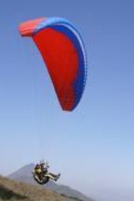
Paraglider circa 2005.
Zoom
Seats: 1.
DHV: 2.
Zoom Race
Seats: 1.
Paraglider circa 2005.
Zoom
Seats: 1.
DHV: 2.
Zoom Race
Seats: 1.
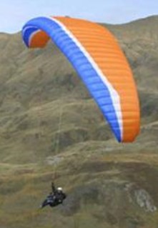
Paraglider circa 2005.
Bolero 3 large
DHV 1
Pilot weight: 100 – 120kg
Wing area: 30.93 sq.m
Bolero Plus XL
Pilot weight: 115-140 Kg
DHV 1
Seats: 1
Bolero 4 Medium
Pilot weight: 80-105 kg
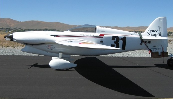
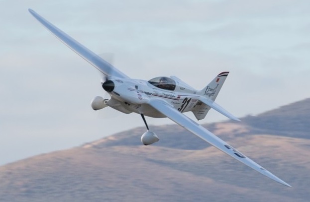
Constructed as a DG2 it was registered to Lowell J. Slatter, Buhl, ID on 18 June 2011 with new c/r N390DG. Originally designed and built by Dan Gilbert and incorporating the lessons learned from his DG-1 (last raced by Charlie Greer as Miss B Haven), this aircraft has a fuselage similar to Nemesis but significantly scaled down and with a ventral fin to raise the tail wheel up. Lowell had done considerable developmental flying and enlarged the rudder to improve directional control.
From 9 September 2013 to 15 September 2013 it raced as #31, named Fraed Naught. Competed at the National Championship Air Races in the Formula One class. The primary pilot was Lowell Slatter from Brookville, OH. Finished in 4th place with an average speed of 227.225 mph.
From 12 September 2016 to 18 September 2016 competed at the National Championship Air Races in the Formula One class. The primary pilot was Lowell Slatter from Buhl, ID. Qualified in 1st place with an average speed of 253.787 mph. Raced in the Gold race. Finished in 1st place with an average speed of 256.728 mph.
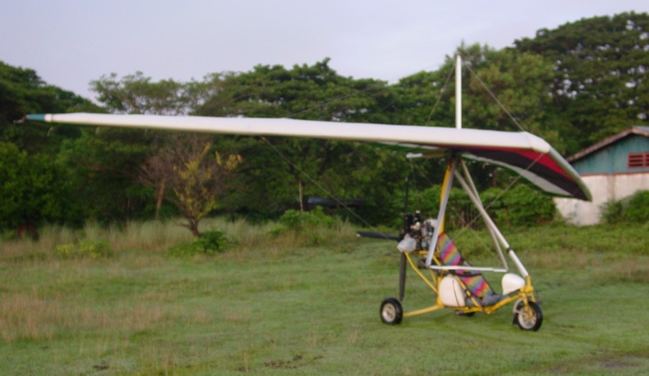
The aircraft was designed by Mark Gibson and produced by his company, GibboGear of Winter Haven, Florida, for the Fédération Aéronautique Internationale microlight class, with the intention of reversing the trend of its period of trikes becoming heavier, more expensive, stall faster, be harder to fly and thus require more flight training. The Butterfly addresses these issues by being a simple design and by employing a single surface wing with a large 240 sq ft (22 m2) area. Similarly the carriage is simple and lacks options, to reduce cost and weight. The resulting aircraft has a low landing speed of 20 mph (32 km/h) at the cost of a low cruise speed of 25 mph (40 km/h).
The Butterfly features a cable-braced hang glider-style high-wing, weight-shift controls, a single-seat, open cockpit, tricycle landing gear and a single engine in pusher configuration. The aircraft’s single surface wing is made from bolted-together aluminum tubing, covered in Dacron sailcloth. The wing is supported by a single tube-type kingpost and uses an “A” frame control bar. When the aircraft was in production the wing was also available from the factory as a kit, as well as fully assembled. The landing gear uses tubular suspension and the nose wheel is steerable. The engines that were factory-supplied included the twin-cylinder, two-stroke air-cooled 40 hp (30 kW) Rotax 447 and 50 hp (37 kW) Rotax 503.
The aircraft was supplied as a kit for amateur construction at a 2000 price of US$10,000 but buy 2017 was out of production.
Engine: 1 × Rotax 447, 40 hp (30 kW)
Wingspan: 32 ft 10 in (10 m)
Wing area: 240 sq ft (22 sq.m)
Empty weight: 290 lb (132 kg)
Gross weight: 660 lb (299 kg)
Fuel capacity: 10 U.S. gallons (38 L; 8.3 imp gal)
Cruise speed: 25 mph (40 km/h; 22 kn)
Stall speed: 19 mph (31 km/h; 17 kn)
Rate of climb: 750 ft/min (3.8 m/s)
Crew: one
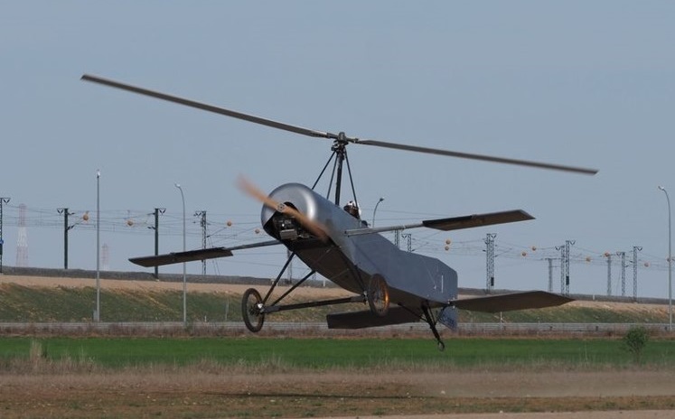
The project is the result of a decision by a group of friends at the Getafe Ultralight Club to commemorate the centenary of Juan de la Cierva’s historic first flight in his C.4 during January 1923. Following more than a thousand hours of design and fabrication work, the replica C.4 was ready for its official unveiling in January at Getafe Air Base, not far from the very spot where the original had first taken flight a hundred years earlier. The public unveiling took place at Camarenilla aerodrome March 2013, but the team chose to move the aircraft to Ocaña for its first flight. They disassembled the replica C.4 in the morning, driving it to the historic Ocaña Aerodrome by truck and then reassembling it.
Initial ground tests without the (unpowered) main rotor fitted, were carried out to check the engine operation and to test the aircraft in high-speed taxiing. After the crew fitted the rotor, a test run took place just a little after 6:00 p.m. local time. Pilot Fernando Roselló began the taxi run – but the autogiro lifted off briefly and then landed gently.
After this small jump, other takeoffs followed, until, finally, the Cierva took off and completed a couple of full circuits. Nerves, illusion and adrenaline were rewarded by seeing the autogyro take off from the ground without incident and land again successfully.
This particular early model does not having direct control through the inclination of the rotor hub, but rather still retains roll and elevator control with ailerons and rudder. While the replica C.4 stays true to much of the original design concept, the replica team chose to include some safety concessions, such as a modern engine and a well-proven, two-bladed rotor design (in place of the original four-bladed system which had only a marginal useful life of just a few hours flight time). One of the team engineers added that the rotor system, as it is without direct control, is based on Cierva’s patent, number 100595 of Dec 1926.
After alighting, Fernando Roselló stated that the aircraft behaved just as he had expected. It is a very stable aircraft, but since it lacks direct control (using aerodynamic control instead) it is slower to respond to control input. He flew as slowly as 50km/h and estimated a cruise of about 80km/h at about 4,500rpm, comparing it to 4,700rpm on his 80HP Rotax powered 912 gyroplane which flew at 80km/h with a positive variometer (rate of climb indicator).
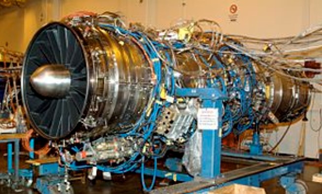
The General Electric/Rolls-Royce F136 was an advanced turbofan engine being developed by General Electric and Rolls-Royce plc for the Lockheed Martin F-35 Lightning II. The two companies stopped work on the project in December 2011 after failing to gather Pentagon support for further development.
All early F-35s were to be powered by the Pratt & Whitney F135 but it was planned that engine contracts would be competitively tendered from Lot 6 onward. The engines selected would be either the F135 or an engine produced by the GE/RR Fighter Engine Team and designated the F136. The GE/RR Fighter Engine Team was a co-operation between GE Aviation in Cincinnati, Ohio, United States (60% share) and Rolls-Royce in Bristol, United Kingdom and Indianapolis, Indiana, USA (40% share).
On 21 July 2004, the F136 began full engine runs at GE’s Evendale, Ohio facility. The engine ran for over an hour during two separate runs. In August 2005, the United States Department of Defense awarded the GE and Rolls-Royce team a $2.4 billion contract to develop its F136 engine. The contract was for the system development and demonstration (SDD) phase of the F136 initiative, scheduled to run until September 2013.
The US Defense budget announced on 6 February 2006 excluded the F136 — leaving Pratt & Whitney, maker of the F135 engine, as the sole provider of engines for the Lockheed Martin F-35 fighters. Congress, however, overturned this request and allocated funds for FY 2007 later in 2006. In November 2006, the General Electric/Rolls-Royce team successfully completed a 3-month preliminary design review by the F-35 Program Office and the prime contractor, Lockheed Martin.
On 13 February 2008, the GE Rolls-Royce Fighter Engine Team successfully completed its Critical Design Review (CDR) for the F136. During CDR, the U.S. Government’s Joint Program Office for the F-35 Lightning II validated and approved the design of the engine. Also during the review, every aspect of the engine design was analyzed and evaluated in order to proceed with the building of the first full development engines. The process involved 80 detailed component and module design reviews, involving technical experts from the JPO, General Electric and Rolls-Royce.
On 20 March 2008, the F136 successfully completed a high-altitude afterburner testing program at the US Air Force Arnold Engineering Development Center in Tennessee, including common exhaust hardware for the F-35 Lightning II aircraft. All test objectives were reached as planned using an engine configured with Conventional Takeoff and Landing (CTOL) and Short Takeoff Vertical Landing (STOVL) common exhaust systems. The engine configuration included a production-size fan and functional augmenter allowing several run periods to full afterburner operation. The GE Rolls-Royce Fighter Engine Team successfully completed Short Take Off, Vertical Landing (STOVL) testing on an F136 engine at the GE testing facility at Peebles, Ohio on 16 July 2008.
The first complete new-build F136 engine began testing 30 January 2009, under the System Development and Demonstration (SDD) contract with the US Government Joint Program Office for the F-35 Joint Strike Fighter program. This marked the first complete engine assembled following US Government validation of the F136 design in 2008. The milestone was achieved one month ahead of schedule.
Citing the Weapon Systems Acquisition Reform Act of 2009, the GE Rolls-Royce Fighter Engine Team submitted an unsolicited fixed-price offer for the F136 to the Pentagon on 28 September 2009. The fixed-price approach would cover initial F136 engine production, beginning with the F136 second production lot. According to the GE Rolls-Royce Fighter Engine Team, the proposal would shift significant cost risk from taxpayers to the Fighter Engine Team until head-to-head competition begins between the F136 and the Pratt & Whitney F135 engine in 2013.
From 2006 to 2010 the Defense Department has not requested funding for the alternate F136 engine program, but Congress has maintained program funding.
On 19 December 2009, U.S. Congress approved continued funding for the F136 engine program in fiscal year 2010. The U.S. Defense Department did not request FY 2010 funding for the F136 engine program. In a report filed on 18 June 2009, the House Armed Services Committee cited Pratt & Whitney F135 engine program cost overruns of $1.872 billion as cause to continue funding the F136 engine.
On 2 November 2009, the F136 team said that they would redesign a small part of the diffuser leading to the combustor after a failure during testing. Testing resumed on January 22, 2010. The GE Rolls-Royce Fighter Engine Team is currently in the fourth year of its System Development and Demonstration (SDD) contract with the US Government Joint Program Office. The Fighter Engine Team has totaled more than 800 hours of testing on pre-SDD and SDD engines. In early 2010, full afterburning thrust was reached in testing of the first production standard engine.
On 24 March 2011, the Department of Defense issued a 90-day temporary stop work order after Congress failed to pass the defense budget. GE declared that it would continue work on the engine program with their own funds in spite of the stop-work order, as allowed in the order and as had been suggested by Schwartz the previous year. However GE is limited to design work only, as the stop-work prevents their use of the existing hardware.
On 12 April 2011, GE reduced its team on project from 1,000 workers down to 100, who will work on the F136 and engine technologies for “future combat aircraft”. GE will redeploy the workers to commercial projects, but will not hire the hundreds of new engineers it was expecting. On 25 April 2011, the Department of Defense ended the contract with GE and demanded that the engines built to date be turned over.
On 5 May 2011, GE and RR offered to pay for the development through FY2012 and asked for access to the materials. By switching to self funding the cost would reduce from $480 million a year to only $100 million, 60% to be paid by GE and 40% to be paid by RR. After self-funding the project GE and Rolls-Royce announced on 2 December 2011, that they would not continue development of the F136 engine because it is not in their best interest.
The F136 produces 18,000 lbf (80.1 kN) of lift thrust in STOVL configuration. Combined with thrust from the LiftFan (20,000 lbf or 89.0 kN) and two roll posts (1,950 lbf or 8.67 kN each), the Rolls-Royce LiftSystem produces a total of 41,900 lbf (186 kN) of thrust. This compares with the maximum thrust of 23,800 lbf (106 kN) for the Harrier’s Rolls-Royce Pegasus engine.
Specifications:
Type: Twin-Spool, Augmented Turbofan
Length: 221 in (5.6 m)
Diameter: 48 in (1.2 m)
Compressor: Twin Spool/Counter Rotating/Axial Flow/Low Aspect Ratio
Combustors: Annular Combustor
Turbine: Axial Flow/Counter-Rotating
Maximum thrust: 40,000 lbf; 25,000 lbf without afterburner

General Electric ran performance tests of its 32,000 lb.-thrust F 110-GE-132 engine for Block 60 F-16s at its Peebles, Ohio, facility.The engine, the first complete, purpose-built F 110-132 began about 30 hr. of runs at Peebles on an outdoor test stand. Preceding those trials were 30 hr. of tests conducted in indoor facilities at GE’s Evendale, Ohio, plant. Those assessments were finished in midNovember 2000.
Thrust is the biggest difference between the F 110-132 and the production version of the F 110, the F 110-129. The newer engine is capable of generating about 3,000 lb more thrust under sea-level static conditions. To generate that power, the -132 is fitted with a 5% more efficient fan that features integrally bladed disk construction. The new powerplant also has a filament wound graphite-epoxy fan duct designed to handle the loads associated with thrust vectoring, should that technology ever be added to the engine.
The F 110-132 is equipped with a radial augmentor, similar to the unit found in the F/A-18E/Fs F414 engine. It improves operability at higher thrust levels and helps eliminate augmentor screech-high-frequency, standing sound waves that can damage engine components.
Also offered as an option on the F l10-132 is an ejector nozzle that directs a thin film of cool air from the engine bay around the nozzle’s flaps and seals. Cooling is great enough to reduce the temperatures of those components by 400-800 deg. F, depending on operating conditions.
Taken together, the F 110-132 improvements can be used to generate additional thrust, or to increase engine life if thrust is limited to 29,000 lb. This means inspections now carried out on F 110s at 4,300 cycles would be delayed to 6,000 cycles.
F 110-132s operated under the increased durability option would carry the official USAF designation of F 110-GE-132As. Despite the designation, the service has not taken any steps toward procurement.
Applications:
F-14B/D Super Tomcat
F-15S/F-15K/F-15SG/F-15SA Strike Eagle
F-16 Fighting Falcon
General Dynamics F-16XL
Mitsubishi F-2
Specifications:
F110
Type: Afterburning turbofan
Length: 182.3 – 232.3 in (463 – 590 cm)
Diameter: 46.5 in (118 cm)
Dry weight: 3,920 – 4,400 lb (1,778 – 1,996 kg)
Compressor: 2 spool: 3 fan and 9 high pressure compressor stages
Combustors: annular
Turbine: 2 low-pressure and 1 high-pressure stages
Maximum thrust: 27,000 – 28,000 lbf (120 – 125 kN)
Overall pressure ratio: 29.9:1 – 30.4:1
Turbine inlet temperature: 2750F (1510C)
Thrust-to-weight ratio: 6.36:1

The F 16 was not originally planned as an equipment item for the inventory, but as a candidate for a Light Weight Fighter (LWF) technology demonstrator programme to examine the possibility of building a fighter significantly smaller and cheaper than the F 15. Five companies submitted proposals for an LWF on February 28, 1972, General Dynamics and Northrop were selected to build two prototypes each, designated YF 16 and YF-17, respectively, on April 13, 1972, and on January 13, 1975, the Secretary of the Air Force announced that the F 16 was the final choice. By this time, the emergence of a market, especially among a group of European NATO nations, had caused the programme rather quickly to be recast as an Air Combat Fighter (ACF), with procurement of an operational version promised by the USAF. At the same time, the original concept of a light and uncompromised close-combat dogfighter was changed to include all-weather capability in both the air to air and air to surface roles, with heavy loads of the full spectrum of tactical stores.
General Dynamics F-16 Fighting Falcon Article
The first of two prototypes (72-01567) of the YF-16 (GD model 401) was airlifted from Fort Worth to Edwards AFB in January 1974 and was officially flown for the first time of the 2nd of February 1974, although this aircraft had made an unofficial and unscheduled flight on 20 January after becoming airborne in the hands of Philip Oestricher, who elected to take off when the tailplane was damaged during high-speed taxi tests. An ‘official’ first flight followed on February 2, and subsequent testing was encouraging.
The chosen engine was a single Pratt & Whitney F100 PW 100 two shaft augmented turbofan, with maximum thrust rating of 10800 kg (23810 lb) with full afterburner. This engine was chosen because it was already fully developed and in production for the F 15. Although it has a modulated variable profile nozzle, it is fed from a simple fixed inlet and ventral duct to reduce complexity and cost. This reduces maximum high altitude Mach number to below 2.0, but this is considered of little consequence. Virtually all modern air combat takes place at medium to low altitudes at speeds in the order of 650 km/h (404 mph), and turn radius is far more important than speed. The F 16 pilot sits in a reclining McDonnell Douglas seat (of course, with zero/zero capability) and flies with a sidestick controller resembling a miniature control column on the right cockpit console. This small controller is easy to manage under conditions of high g acceleration, and the sloping seat also helps the pilot resist g forces. The controller hardly moves under the pilot’s input demands; instead it contains transducers which sense the pilot’s applied forces. The resulting electrical signals, and those from the rudder pedals, serve as primary inputs to a fly by wire (FBW) control system which also includes the digital autopilot, computer, weapon delivery system and power units driving the flight controls.

The wing and fuselage are blended structurally and aerodynamically and, like the tail, incorporate major portions of graphite‑epoxy composite, glass‑fibre, titanium and other advanced materials. There are only five ribs in each wing, but no fewer than 12 spars, all linked to body frames. Long vortex extensions at the root give powerful lift at high angles of attack and allow the wing proper to be made significantly smaller. Along the top of the left extension strake is the M61 20‑mm (0.79‑in) cannon, with a 500‑round ammunition drum lying transversely in the top of the fuselage. About 3162 kg (6971 lb) of fuel is housed in various cells in the wing and fuselage which are governed as two tanks, with a flight‑refuelling receptacle in the top of the mid‑fuselage matched to the SAC Flying Boom type of refuelling method.
Moveable leading-and trailing-edge flaps, controlled automatically by the aircraft’s speed and attitude, enable the wing to assume an optimum configuration for lift under all conditions of flight. All flying controls are operated by a ‘fly-by-wire’ electronic system.
The F-16 has a single vertical tail surface, mid-set all-moving tailplane and mid-set wings of 40 degree leading-edge sweep.
The tailplane is of the taileron type, the two halves operating in unison for pitch control and differentially for roll control.
The full-span ailerons are of the flaperon type, again operating differentially for roll control and in unison for increased lift.
The leading edges are hinged to allow the automatic flight-control system to schedule them as automatic leading-edge flaps and, in concert with the ‘flaperons’, provide a measure of variable camber to the wing.
Take-off and landing has the leading edge flaps at 2 degrees and the flaperons down 20 degrees.
Initial climb has the leading-edge flaps angled down at 15 degrees and the flaperons down at 20 degrees.
High speed flight has the leading-edge flaps and the flaperons both at 2 degrees up.
For manoeuvring, the leading-edge flaps are angled down at 25 degrees and the flaperons level.
Approach has the leading-edge flaps at 15 degrees and the flaperons down at 20 degrees.
In the nose is a Westinghouse X‑band pulse‑doppler radar, with planar‑array aerial. It can function in many modes including air-to‑air look‑up or look‑down, auto‑acquisition dogfight, air‑to‑ground ranging, ground mapping, expanded mapping, doppler beam-sharpening, beacon, ‘freeze’ (fixed display), and two types of Sea Mode for anti-shipping missions. Delco make the computer, Marconi‑Elliott of Britain, the advanced HUD (head‑up display), Kaiser the head‑down display (HDD) and Singer‑Kearfott the inertial navigation system. Up to 6894 kg (15 200 lb) of weapons, ECM pods and tanks can be carried on nine pylons.
The YF-16 prototypes were being flown by six pilots, two each from General Dynamics, the Air Force Flight Test Centre and the Tactical Air Command. The single-seat, single-engine aircraft, 47 feet long with a 30-foot wingspan, is designed as a compact, low-cost fighter for air-to-air combat. It also can carry nearly 9,0001b of missiles and bombs for air-to-ground missions. The YF-16 is powered by a Pratt & Whitney F-100-PW-200 turbofan, the same engine used in the Air Force F-15 fighter. The F-100 engine produces about 25,0001b / 10814kg of thrust with full afterburner.
The F-16 is built in three major subsections. Some 80 percent of the airframe is made of conventional aluminium alloy, and about 60 percent is from sheet metal. Steel, composites and titanium represent about 8 percent of the structure. The wing is a cropped delta with a 40-degree leading-edge sweep. It has a 4 percent thickness/chord ratio and a 64A204 airfoil section. The structure consists of eleven spars and five ribs. Upper and lower skins are machined from a single piece. The wing is blended into the fuselage which creates a significant stowage area for internal fuel, which accounts for 31 percent of the loaded weight of the F-16. Leading edges are blended into the fuselage with strakes which, at high angles of attack, create vortices that maintain energy in the airflow over the wings, delaying root stalling and contributing to directional stability. Trailing edges have inboard “flappers” which combine the functions of flaps and ailerons. They can be drooped to 20 degrees. Leading-edge flaps contribute to the aircraft’s legendary manoeuvrability. The single vertical tail is of multi-rib, multi-spar construction in aluminium, with the skin made of graphite epoxy. Two ventral fins are made of glass fibre. There is an all-flying tailplane. Main and nosewheel gear retract into the fuselage. The single air intake is mounted underneath the fuselage, giving the F-16 its distinctive profile. This location was chosen to provide minimal airflow disturbance over a wide range of aircraft attitudes. Location of the nosewheel gear aft of the intake means that FOD (foreign object damage) ingestion problems have been minor. The intake is of fixed geometry. A separation strut provides additional tunnel ridigity. Many parts are interchangeable between port and starboard including the horizontal tail surfaces, flaperons and most of the main landing gear. The view from the cockpit is exemplary. A polycarbonate clamshell canopy encloses the pilot who sits on an ACES II rocket powered ejection seat, cleared for ‘zero-zero’ performance up to 600 knots and/or 50,000 ft. The inside of the canopy is tinted with a thin gold film, which dissipates radar energy. The seat is raked backwards at 30 degrees, to enhance the pilot’s ability to withstand high g. Instead of a conventional control column, the F16 is fitted with a sidestick controller mounted to starboard. “Fly-by-wire” powered controls and artificial “feel” require the sidestick to be moved only millimetres.
In April 1975, the first definitive USAF contract specified six F‑16As and two tandem‑seat dual‑control F‑16B trainers with full combat capability (the B has 17% less internal fuel). The USAF said it would buy 650 aircraft in all, but this total was subsequently been increased to a currently planned force of 1388 aircraft. On June 7, 1975, at the Paris air show, it was jointly announced by Belgium, Denmark, the Netherlands and Norway that they had selected the F‑16 over two other candidate aircraft to replace the F‑104, buying initial totals of: Belgium 90A+ 12B+ 14 options; Denmark 40A+8B+ 10 options; the Netherlands 84 (A, B combined)+ 18 options; and Norway 60A+ 12B (no options).
In September 1976, Iran ordered 160 from the US Government, signifying its eventual requirement for a total of 300. Iran is unlikely to participate in manufacture, but the four European countries signed a complex collaborative/offset deal which gives them the right to make major parts of the airframe, engine and equipment, both for their own purchases and those of other customers including the USAF. Since 1976, Turkey has expressed a wish to join this consortium, but no decision had been announced by them by early 1978.

The first production F 16A (75 0745) flew on 8 December 1976 at Fort Worth, Texas, and the first F 16B on August 8, 1977. The first operational F-16A was delivered in January 1979 to the 388th Tactical Fighter Wing at Hill Air Force Base, Utah and its first overseas unit, the 8th TFW at Kunsan AB, South Korea, on 1 November 1980. The first USAF unit in Europe to re-equip with Fighting Falcons was the 50th TFW at Hahn AB, West Germany on 1 December 1981.
As part of a major policy decision to upgrade the equipment operated by second-line units, the F-16 has already reached the South Carolina Air National Guard, deliveries beginning in mid-1983, followed by other ANG units, as the aircraft were replaced in USAF by later models.
Initial USAF production versions were the F-16A single-seater and F-16B two-seat operational trainer with an extended canopy and dual controls, powered by Pratt & Whitney F100 engines and equipped with APG-66 radars. Four European countries selected the F-16A/B, with manufacture by a consortium with two final assembly lines, in Belgium and The Netherlands.

The European F-16A/B aircraft have been upgraded under the Mid-Life Update program and designated F-16AM/BM.
The F-16C and F-16D aircraft, which are the single- and two-place counterparts to the F-16A/B, incorporate modern cockpit control and display technology. The F-16C/D models were the result of a multi¬national staged improvement programme (MSIP) initiated in 1980. Changes include the introduction of a more capable APG-68 radar with increased detection range and track-while-scan mode, plus new cockpit displays with multifunction CRTs and a wide-angle headup display and an increase in the maximum take-off gross weight. First flown in December 1982, the F-16C/D became the standard production model, although the earlier F-16A/B was still available for export. Following General Elec-tric’s success in the Alternate Fighter Engine competition, F-16C/Ds delivered from FY1985 have comprised mixed batches of General Elec¬tric F110 and Pratt & Whitney F100-220 powered aircraft. Engine contracts are to be agreed annually, with the lowest bidder supplying the majority of the power plants for that year. In FY1985 General Electric provided 75 per cent of the engines needed for F-16C/D production. Export aircraft are available with either engine. The TUSAS organisation in Turkey is to build F-16C/D aircraft and F110 engines for the Turkish Air Force, which is purchasing 160 aircraft, including an initial batch supplied by General Dynamics. Deliveries of TUSAS assembled F-16s is scheduled to begin in 1988.
The F-16CJ is a modified F-16C for the SEAD role.
By June 1987 2,975 F-16s of all versions had been ordered, including aircraft for licence production (Turkey – 278, South Korea – 108, Belgium – 222, Netherlands – 300), and 1,774 had been delivered.
Early in 1987 Bahrain became the 16th nation to order the F-l6, contracting for 12 aircraft powered by General Electric F110 engines.
The Block 60 F-16E single and F-16F two-seat fighters feature technology improving the combat effectiveness and multi-role capability of the aircraft. Deliveries of these variants started to the United Arab Emirates as the first customer. The first Block 60 made its maiden flight in December 2003.
Israel took delivery of the F-16I, which is a customized version of the F-16E/F with Israeli avionics and weapons.
The F-16R is a reconnaissance version with an underfuselage pod, and the F-16N is an ‘Aggressor’ version for the US Navy.
General Dynamics has elected to improve the overall performance of the F 16 in the ground attack role by installing a new cranked arrow wing. With 120 per cent more wing area and two fuselage plugs lengthening the fuselage 54 ft 1.86 in (16.51 m) to accommodate the longer root chord, the double delta F 16XL carries 82 per cent more internal fuel. Stores are carried tangentially to the wing undersurface on 17 hardpoints, and drag fully loaded is some 60 per cent less than with conventional carriage. Radar cross section is also halved. The reduction in drag and the greater fuel capacity has a dramatic effect on the F 16XL’s payload/range performance, enabling the aircraft to carry twice the payload of an F 16A to a 45 per cent greater combat radius. Penetration speeds are increased by up to 100kt to around Mach 0. 9. Air to air performance is also improved, with the 9g manoeuvre envelope doubling in size. Manoeuvre capability fully loaded is also improved from 5.5g to 7.33g. Instantaneous turn rate is increased. The variant first flew on 3 July 1982.
The Air Force’s evaluation involved four F 15s and two F 16XLs. Boeing, Rockwell and McDonnell Douglas co operated with NASA to set up a series of supersonic laminar flow tests involving a single seat F 16XL in flights beginning in 1991. When these showed promise, a two seat XL was used for the second series of fights during which more than 40 flights were completed by late 1996. Research results indicate it is possible to make a 4% weight saving by applying a laminar flow wing to supersonic airliners. Of the two F 16XLs built by GD as a private venture, one is a single seater powered by a Pratt & Whitney F100 and the other is a two seater powered by the General Electric F110.

The F-16XL has a 56in / 1.42m longer fuselage boosting fuel capacity by 80%.
The F-16XL has a maximum of 29 hardpoints available on 17 stores stations. The stores stations are semi-conformal to minimise drag, which is 58% less than that of the F-16, enabling the F-16XL to carry twice the payload 45% further than the basic F-16.
During the 1970s and early 1980s considerable research was undertaken into a host of aeronautical fields but this was generally performed with conversions of existing aircraft such as the F-16 Fighting Falcon converted by General Dynamics into the F-16/AFTI for investigation of direct-force controls within the overall context of the CCV (Control-Configured Vehicle) portion of the Advanced Fighter Technology Integration programme, which was intended to create a quantum leap in fighter manoeuvrability.
The very first YF-16 (72-1567) was rebuilt in December 1975 to become the USAF Flight Dynamics Laboratory’s Control-Configured Vehicle (CCV). Fly-by-wire flight controls and relaxed static stability found on all Vipers made the YF-16 an ideal candidate to evaluate control of an aircraft beyond conventional means, with independent or ‘decoupled’ flight surfaces. The YF-16/CCV could rise or fall using direct lift, move laterally by direct side force, or yaw, pitch, or roll regardless of the direction of flight. Twin vertical canards beneath the air intake and flight controls permitted use of wing trailing edge flaperons in combination with the all-moving stabilator. The YF-16/CCV flew on 16 March 1976, piloted by David J. Thigpen. On 24 June 1976, the ship was seriously damaged in a landing after its engine failed on approach. The flight test programme was resumed and lasted until 31 July 1977, when 87 sorties and 125 air hours had been logged.
Early in the development stage, General Dynamics wanted to market a simpler version of the F-16 for export, and teamed up with General Electric to create a version powered by the 8165kg thrust General Electric J79-GE-17X single-shaft turbojet, a development of the engine employed on the F-104 Starfighter and F-4 Phantom. As the J79-GE-119, this engine was installed on a full-scale development F-16B (75-0752) bailed back from the USAF. The Turbojet required a lower airflow than the P&W FI00-PW-200 used on all production F-16A/Bs so the shape of the air intake was altered. Since the J79 engine was 18 in (46 cm) longer than the F100, the rear fuselage was extended aft of the stabilator pivot point by that amount. The resulting F-16/79, made its first flight on 29 October 1980, and was existant in F-16/79A (single-seat) and F-16/79B (two-seat) versions.
General Dynamics F-16/79 Article
The F-16/101 was a similarly re-engined example powered by a General Electric YJ101 two-shaft augmented turbojet engine delivering about 15,000 lb (6803 kg) thrust, had performed well on the Northrop YF- 17 and its builder wanted to demonstrate the much improved DFE (derivative fighter engine) version, capable of up to 26,500-lb (12,020-kg) thrust on a single-engine F-16. The retrofit was made on this first full scale development F-16A (75-0745) which flew with the GE engine on 19 December 1980. The F-16/101 made 58 test flights and logged 75 air hours before the programme ended in July 1981. The F-16/101 was not adopted but the way had been paved for development of an improved GE engine, the F 110, on the Fighting Falcon beginning with F-16C block 30/32 aircraft.
In June, 1975, four European countries (Belgium, Netherlands, Derunark, and Norway) announced plans to purchase 348 fighters. In February 1978, the first European F-16 assembly line opened at Sabca/Sonaca where Belgium took delivery on 29 January 1979 of the first locally-manufactured F-16 out of the country’s original order for 116 aircraft (96 F-16As and 20 F-16Bs).
Belgian F-16As were serialed FA-01/136 (78-116/161; 80-3538/3546; 80-3547/3587; 86-0073/0077; 87-0046/0056; 88-0038/0047; 89-000110011; 90-0025/0027). F-16Bs were serialed FB-01/24 (78-0162/0173; 80-3588/3595; 87-0001; 88-0048/0049; 89-0012). FA-01/55 and FB-01/12 were upgraded to F-16A/B block 10 standard, while FA-56/136 and FB-25/24 were built as F-16A block 1s (big tail) aircraft.
Norway acquired seventy-two F-16A and B model Lawn Darts (sixty F-16As and twelve F-16Bs) from the Netherlands’ Fokker production line between 15 January 1980 and 4 June 1984. Six F-16A/B block 15 (four F-16A and two F-16B) attrition replacements were later ordered.
Norway employs the F-16 in a defensive role, Scandinavian geography dictating an important anti-shipping mission. On 12 December 1979, the first Fighting Falcon for the RNAF completed its maiden flight from Fokker’s Schipol plant.
Norwegian aircraft have drag chutes to operate on snowy and an identification spotlight for use during long dark winters.
In April 1978, the second European F-16 assembly line (after Belgium) opened at Fokker-VFW in the Netherlands. In May 1979, the first Dutch-assembled F-16 made its maiden flight. Holland later increased its F-16 purchase from 102 to 213 aircraft.
The USAF continues large-scale procure¬ment of F-16s, with the 180 approved in FY1986 taking total purchases to 1,859. In October 1986 the F-16 won the Air Defence Fighter (ADF) competition, a modified version of the F-16A being selected instead of the Northrop F-20A Tigershark. The ADF contract will cover the modification of existing F-l6As, and will not be for new-build aircraft. In April 1987 the US Navy took delivery of the first F-16N supersonic adversary aircraft of the 26 ordered.
By 1994, production of the F-16 had been taken over by Lockheed Martin.
The F-16 Block 70 variant, also known as the F-16V, features cutting-edge enhancements including the AN/APG-83 AESA radar, new mission computers, a digital cockpit, and advanced electronic warfare systems. These upgrades provide superior situational awareness, survivability, and multirole performance.
On 18 March 2005, Lockheed Martin Aero plant in Fort Worth, Texas, delivered the final F-16 Fighting Falcon for the US Air Force; F-16CJ 01-7053. Lockheed Martin continues to produce the F-16 fighter for international customers. A total of 2231 F-16s have been produced for the U.S. Air Force.
Variants:
F-16A
F-16B
F-16C
F-16CJ
F-16D
F-16E
F-16F
F-16I
F-16N
F-16R
F-16XL
Operators:
USAF, US Navy, Bahrain, Belgium, Chile, Denmark, Egypt, Greece, Indonesia, Israel, Italy, Japan, Jordan, Netherlands, Norway, Oman, Pakistan, Poland, Portugal, Singapore, South Korea, Thailand, Taiwan, Turkey, United Arab Emirates, Venezuela
Specifications:
YF-16 (model 401)
Engine: 1 x Pratt & Whitney F100 PW 100 turbofan, 10800 kg (23810 lb)
Length: 47 ft
Wingspan: 30 ft
Fuel: 3162 kg (6971 lb)
External stores: 6894 kg (15 200 lb)
Armament: M61 20 mm (0.79 in) cannon, 500 round
Pylons: nine
Seat: 1
YF-16
Engine: Pratt & Whitney F-100-PW-200 turbofan, 25,0001b / 10814kg thrust
Maximum speed: Mach 1.95
F-16A
Engine: P&W F100-220, Normal-12,420 lb st, military-14,670 lb st, afterburn-23,830 lb st.
Length: 47.638 ft / 14.52 m
Height: 16.699 ft / 5.09 m
Wingspan: 31.004 ft / 9.45 m
Wing area: 300 sq ft (27,9 sq.m).
Max take off weight : 35390.3 lb / 16050.0 kg
Empty wt: 15,137 lb (6 865 kg).
Internal fuel: 6,972 lb (3 162 kg).
Max. weight carried : 19800.9 lb / 8980.0 kg
Air superiority gross weight: 23,357 lb (10952 kg) with ammunition and two Sidewinders.
Wing loading: 78 lb/sq ft (397 kg/ sq.m).
Thrust/weight ratio: 1.02.
Max. speed : 1158 kts / 2145 km/h
Cruising speed : 533 kts / 988 km/h
Initial climb rate : 41338.58 ft/min / 210.0 m/s
Service ceiling : 50000 ft / 15240 m
Range : 1042 nm / 1930 km
Fuel fraction: 30%.
Armament : 1x MK 20mm M61A1, 5440kg ext 9pt. / 2-6 AIM-9 Sidewinder
Seats: 1.
F 16B
Engine: P&W F100-220, Normal-12,420 lb st, military-14,670 lb st, afterburn-23,830 lb st.
Wingspan: 10m.
Length: 15.03m.
Height: 5.09m.
Wing area: 27.9sq.m.
Empty wt: 7909 kg.
Internal fuel: 2745 kg.
MTOW: 16,057 kg.
Seats: 2
F-16C
Engine: General Elec¬tric F110
Seats: 1
F-16C
Engine: Pratt & Whitney F100-200 turbofan, 23,840 lb
Wingspan: 31 ft / 9.45 m
Length: 49 ft 6 in / 15.09 m
MTOW: 35,400 lb / 16,057 kg
Max speed: 1350 mph / 2173 kph
Max ferry range: 2415 sm / 3890 km
Armament: 1 x 20 mm cannon (515 rds)
External load: up to 20,450 lb / 9276 kg
F-16C Fighting Falcon
Engine: 1 x Pratt & Whitney F100-220 or General Electric F110-GE-100
Installed thrust (dry – reheat): 67 – 113 kN. / 27,600 – 23,450 lb / 12,519 – 10,637 kg
Span: 10 m / 32 ft 9.75 in
Length: 15.1 m / 49 ft 4 in
Wing area: 27.87 sq.m / 300.0 sq.ft
Height: 16 ft 8.5 in / 4.09 m
Empty wt: 8315 kg / 18,335 lb
MTOW: 19,187 kg / 42,300 lb
Warload: 5413 kg.
Max speed: 1320+ mph / 2124+ kph / M2+ at 40,000ft/12,190m
Initial ROC: 50,000+ fpm / 15,240+ m/s
Ceiling: 18,000+ m.
TO run: 760 m.
Ldg run: 760 m.
Combat radius: 925+ km / 575+ mi
Fuel internal: 4060 lt.
Air refuel: Yes.
Armament: 1 x 20 mm, 2/4/6 x AAM
Hard points: 5 + 2 wing tips.
Disposable stores: 20,450 lb / 9276 kg
Seats: 1.
F-16CJ
Engine: Pratt & Whitney F100, or General Elec¬tric F110 or Pratt & Whitney F100-220
Seats: 1
F-16D
Engine: Pratt & Whitney F100, or General Elec¬tric F110 or Pratt & Whitney F100-220
Seats: 2
F-16E
Engine: 1 x General Electric F110, 7700/13150kg
Max take-off weight: 21770 kg / 47995 lb
Wingspan: 10.4 m / 34 ft 1 in
Length: 16.5 m / 54 ft 2 in
Wing area: 62 sq.m / 667.36 sq ft
Max. speed: 2200 km/h / 1367 mph
Crew: 1
F 16XL
Engine: General Electric F110
Length: 54 ft 1.86 in (16.51 m)
Hardpoints: 17
Penetration speed: Mach 0. 9.
Manoeuvre capability: 7.33g.
Seats: 2
F 16XL
Engine: Pratt & Whitney F100
Length: 54 ft 1.86 in (16.51 m)
Hardpoints: 17
Penetration speed: Mach 0. 9.
Manoeuvre capability: 7.33g.
Seat: 1
F-16/79
Engine: General Electric J79-GE-119
F-16/101
Engine: General Electric YJ101, 26,500-lb (12,020-kg)
Engine: 1 x P+W F-100-PW-100, 112.1kN
Max take-off weight: 9780-15000 kg / 21561 – 33070 lb
Empty weight: 6330 kg / 13955 lb
Wingspan: 9.3 m / 30 ft 6 in
Length: 14.4 m / 47 ft 3 in
Height: 5.0 m / 16 ft 5 in
Wing area: 26.0 sq.m / 279.86 sq ft
Max. speed: M1.2
Ceiling: 19000 m / 62350 ft
Range w/max.fuel: 3200 km / 1988 miles
Range w/max.payload: 500 km / 311 miles
Armament: 1 x 20mm machine-guns, 5000kg of bombs or missiles
Crew: 1
Engine: one 129 kN (26,000 lb st) General Electric F110-GE-129 or Pratt & Whitney F100-P-229 turbofan
Length 15.03m (49 ft 4 in)
Height 5.09m (16 ft 8.5 in)
Wing span (over tip launchers) 9.45m (31ft 0 in)
Take-off weight (clean): 9.791 kg (21,585 lb)
Max Take-Off Weight: 19.187 kg (42,300 lb)
Armament: one 20mm M61A1 Vulcan six-barrel gun 515 rounds; 9276 kg (20,450 lb) of disposable stores
Hardpoints: nine


Electric Boat, set up by American lawyer Isaac Rice, had merged with other companies in the 1950s including Convair aircraft, to make up a new company called General Dynamics.
A major reorganization in 1961 resulted in General Dynamics’ 12 operating divisions being divided into two major groups. On the aerospace side, the Western Group contained components of the Convair division, which itself had originated in 1923 as the Consolidated Aircraft Corporation, merging in 1943 with Vultee Aircraft Inc. to form Consolidated Vultee Aircraft Corporation. Before this, Consolidated had taken over two other aircraft companies, Thomas Morse and Hall Aluminium. In 1954 Consolidated Vultee merged with the General Dynamics Corporation to become the Convair Division, at which time the CV-880 and -990 jet transports were in production, together with F-102 and F-106 fighters, and the B-58 Hustler was at an advanced stage to provide the USAF with its first supersonic bomber (first flown November 1956). Two USAF wings eventually flew B-58As.
In December 1964 the first flight took place of the F- 111, a variable-geometry tactical fighter-bomber which entered USAF operational service from 1968, followed by the FB-111A strategic bomber variant which replaced B- 58As from 1970. In January (officially February) 1974 the first flight took place of the F-16 lightweight fighter for the USAF; selected for engineering and manufacturing development in 1975, but with ground-attack options and provision for radar and navigation avionics suited to all-weather operations. Chosen also for service by European air forces, with European assembly, F-16 deliveries began 1979 (nearly 4,000 delivered by 1999 to many forces worldwide). Light aircraft manufacturer Cessna bought in 1985, but sold to Textron in 1992. The Tactical Military Aircraft division of General Dynamics was bought by Lockheed Corporation in March 1993, becoming Lockheed Fort Worth Company; taking over programs including F-16 and the General Dynamics share in the F-22 (previously a program of three manufacturers: General Dynamics, Lockheed, and Boeing).
General Dynamics acquired Cessna in 1985 but in 1992 sold the company to Textron.
Defense giant General Dynamics bought the business jet maker Gulfstream Aerospace in a stock deal estimated to be worth about $5.3 billion in 1999.
The General Aviation Design Bureau of Ukraine has constructed trike designs for other manufacturers under contract in the past, but the T-32 is their own design. The T-32 Maverick is an ultralight trike that was under development in Kiev in 2011. The aircraft is intended to be supplied as a kit for amateur construction or as a complete ready-to-fly-aircraft.
The T-32 Maverick features a cable-braced hang glider-style high-wing, weight-shift controls, a three-seat open cockpit, with the pilot sitting in front and a two-seat bench in the back, with a cockpit fairing. It can be mounted on tricycle landing gear or floats and has a single engine in pusher configuration.
The aircraft is made from bolted-together aluminum tubing, with its double surface wing covered in Dacron sailcloth. Its 10.2 m (33.5 ft) span wing is supported by a single tube-type kingpost and uses an “A” frame weight-shift control bar. The aircraft has many powerplant options, including the twin cylinder, liquid-cooled, two-stroke, dual-ignition 64 hp (48 kW) Rotax 582 engine, the four cylinder, air and liquid-cooled, four-stroke, dual-ignition 80 hp (60 kW) Rotax 912UL or 100 hp (75 kW) Rotax 912ULS engine and the turbocharged 115 hp (86 kW) Rotax 914. Automotive conversion engines of 60 to 110 hp (45 to 82 kW) can also be fitted.
As a three-seat trike the T-32 Maverick does not comply with the Fédération Aéronautique Internationale microlight or the US light-sport aircraft categories, which are both limited to two seats, but may fit some country’s amateur-built aircraft rules.
At least one has been built.
Engine: 1 × Rotax 912UL, 60 kW (80 hp)
Propeller: 3-bladed composite
Wingspan: 10.2 m (33 ft 6 in)
Wing area: 16.5 sq.m (178 sq ft)
Empty weight: 280 kg (617 lb)
Gross weight: 640 kg (1,411 lb)
Useful load: 360 kg (794 lb)
Fuel: 60 litres (13 imp gal; 16 US gal)
Wing loading: 38.8 kg/m2 (7.9 lb/sq ft)
Maximum speed: 140 km/h (87 mph; 76 kn)
Cruise speed: 100 km/h (62 mph; 54 kn)
Stall speed: 55 km/h (34 mph; 30 kn)
Rate of climb: 3 m/s (590 ft/min)
Crew: one
Capacity: two passengers on a bench seat
