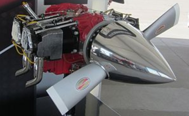
The Lycoming IO-390 engine is a horizontally opposed, four-cylinder aircraft engine, manufactured by Lycoming Engines. There is no carburetted version of the engine, which would have been designated O-390 and therefore the base model is the IO-390.
The engine was originally conceived in the 1970s as the IO-400-X, but the project was never pursued. First run in 2002, the IO-390 family of engines, which Lycoming refers to as the IO-390-X, produce 200 hp (149 kW) to 210 hp (157 kW). The IO-390 was developed from the similar IO-360 engine, by using cylinders from the IO-580 to increase the O-360’s cylinder bore. It features a tuned induction system, roller tappets and Slick Start ignition. The engine has a fuel injection system which meters fuel in proportion to the induction airflow with fuel vaporization taking place at the intake ports. The engine has a displacement of 390 cubic inches (6.39 litres). The cylinders have air-cooled heads.
The IO-390 was first introduced at AirVenture 2002. It has a factory recommended TBO of 2000 hours and requires a dynafocal engine mount. The IO-390 was initially marketed through Lycoming’s custom engine subsidiary, Thunderbolt Engines, prior to the engine’s certification and was at that time only available for installation on non-certified aircraft. The IO-390 was certified on 30 March 2009 to FAR 33 effective February 1, 1965, as amended by 33-1 through 33-24.
In January 2009 the base price of the IO-390-EXP version was USD$$32,650.00.
In November 2009 Lycoming announced that they had obtained an FAA Supplemental Type Certificate to replace the originally fitted Lycoming O-360 engines in the Mooney M20E, M20F and M20J with a new or remanufactured IO-390-A3A6 engine.
Variants:
IO-390-X Four-cylinder, fuel-injected, horizontally opposed, air-cooled direct drive, 390 cubic inches (6.39 litres), 210 hp (157 kW) at 2700 rpm, dry weight 308 lb (140 kg), The “X” designation is a generic indicator for all engines in the family.
IO-390-EXP Four-cylinder, fuel-injected, horizontally opposed, air-cooled direct drive, 390 cubic inches (6.39 litres), 210 hp (157 kW) at 2700 rpm, dry weight 308 lb (140 kg), non-certified engine for experimental aircraft assembled by Lycoming’s Thunderbolt division.
IO-390-A1A6 The initial certified version: four-cylinder, fuel-injected, horizontally opposed, air-cooled direct drive, 390 cubic inches (6.39 litres), 210 hp (157 kW) at 2700 rpm. This model includes provisions for a single-action controllable pitch propeller. Certified 30 March 2009.
IO-390-A3A6 Certified version: four-cylinder, fuel-injected, horizontally opposed, air-cooled direct drive, 390 cubic inches (6.39 litres), 210 hp (157 kW) at 2700 rpm. This model includes provisions for a single-action controllable pitch propeller. This model is similar to the A1A6 but has its propeller flange bushings reindexed. Certified 27 August 2009.
Certified aircraft Cessna 177RG – available in July 2009 under an STC Mooney M20 E, F & J – available in November 2009 under an STC Piper PA-28R Arrow – proposed under STC Symphony SA-160 – proposed as a factory installed 200 hp (149 kW) version, but aircraft no longer in production
Military Aircraft Lancair Synergy T-90 Colombian Air Force
Specifications: IO-390-X Type: 4-cylinder fuel-injected horizontally opposed aircraft engine Bore: 5.319″ (135 mm) Stroke: 4.375″ (111 mm) Displacement: 389 in³ (6.37 litres) Length: 30.70 in (78.0 cm) Width: 34.25 in (87.00 cm) Height: 19.35 in (49.1 cm) Dry weight: 308 lb (140.1 kg) dry Fuel system: fuel-injection Fuel type: 100LL avgas Cooling system: air-cooled Power output: 210 hp (157 kW) at 2700 rpm Specific power: 0.54 hp/in³ (26.0 kW/L) Compression ratio: 8.70:1 Fuel consumption: 11.1 gallons per hour (42 litres per hour) at 65 percent power Power-to-weight ratio: 0.68 hp/lb (1.11 kW/kg)
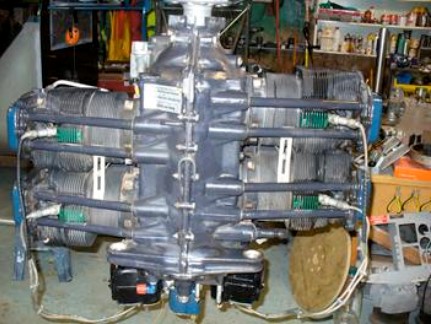
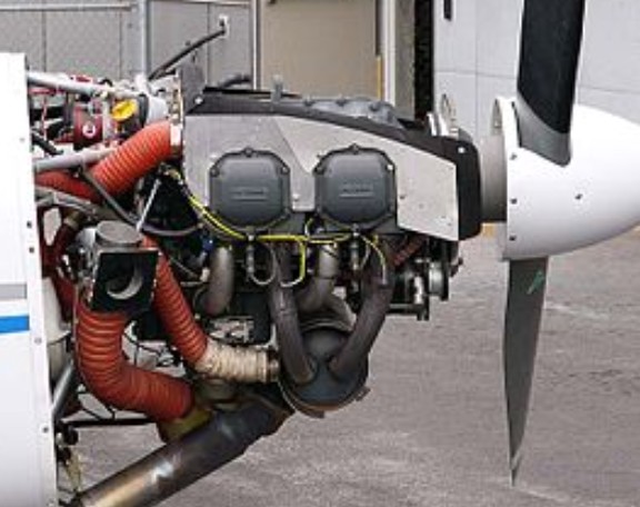
The Lycoming O-320 is a large family of 92 different normally aspirated, air-cooled, four-cylinder, direct-drive engines commonly used on light aircraft such as the Cessna 172 and Piper Cherokee. Different variants are rated for 150 or 160 horsepower (112 or 119 kilowatts). As implied by the engine’s name, its cylinders are arranged in horizontally opposed configuration and a displacement of 320 cubic inches (5.24 L).
The O-320 family of engines includes the carbureted O-320, the fuel-injected IO-320, the inverted mount, fuel-injected AIO-320 and the aerobatic, fuel-injected AEIO-320 series. The LIO-320 is a series of two models identical to the same model IO-320, but with the crankshaft rotating in the opposite direction for use on twin-engined aircraft to eliminate the critical engine.
First run in 1953, the first O-320 (with no suffix) was FAA certified on 28 July 1953 to CAR 13 effective 5 March 1952; this same engine was later re-designated, without change, as the O-320-A1A. The first IO-320 was certified on 10 April 1961, with the AIO-320 following on 23 June 1969 and the first aerobatic AEIO-320 on 12 April 1974. The LIO-320s were both certified on 28 August 1969.
The O-320 family of engines externally resembles the Lycoming O-235 and O-290 family from which they were derived. The O-320 shares the same 3.875 in (98 mm) stroke as the smaller engines, but produces more power with the bore increased to 5.125 in (130 mm). The design uses hydraulic tappets and incorporates the provisions for a hydraulically controlled propeller installation as well. The controllable pitch propeller models use a different crankshaft from those intended for fixed pitch propellers.
The O-320 uses a conventional wet sump system for lubrication. The main bearings, connecting rods, camshaft bearings, tappets and pushrods are all pressure lubricated, while the piston pins, cylinder walls and gears are all lubricated by spray. The oil system is pressurized by an accessory-drive mounted oil pump. A remotely mounted oil cooler is used, connected to the engine by flexible hoses.
The -A, -C and -E variants of carbureted O-320, but none of the high compression or fuel-injected versions, have available STCs that allow the use of automotive fuel as a replacement for more expensive avgas.
Lycoming O-320-D2A
The factory retail price of the O-320 varies by model. In 2010 the retail price of an O-320-B1A purchased outright was USD$47,076.
Variants: O-320 series
O-320 (No suffix) later redesignated O-320-A1A 150 hp (112 kW) at 2700 rpm, Minimum fuel grade 80/87 avgas, compression ratio 7.00:1. Provisions for a controllable pitch propeller and 25-degree spark advance.
O-320-A1B 150 hp (112 kW) at 2700 rpm, Minimum fuel grade 80/87 avgas, compression ratio 7.00:1. Same as A1A but with straight riser in oil sump and -32 carburetor.
O-320-A2A 150 hp (112 kW) at 2700 rpm, Minimum fuel grade 80/87 avgas, compression ratio 7.00:1. Same as A1A but with fixed pitch propeller.
O-320-A2B 150 hp (112 kW) at 2700 rpm, Minimum fuel grade 80/87 avgas, compression ratio 7.00:1. Same as A2A but with straight riser in oil sump and -32 carburetor.
O-320-A2C 150 hp (112 kW) at 2700 rpm, Minimum fuel grade 80/87 avgas, compression ratio 7.00:1. Same as A2B but with retard breaker magnetos.
O-320-A2D 150 hp (112 kW) at 2700 rpm, Minimum fuel grade 80/87 avgas, compression ratio 7.00:1. Same as E3D but with conical mounts.
O-320-A3A 150 hp (112 kW) at 2700 rpm, Minimum fuel grade 80/87 avgas, compression ratio 7.00:1. Same as A1A but with 7/16″ prop bolts.
O-320-A3B 150 hp (112 kW) at 2700 rpm, Minimum fuel grade 80/87 avgas, compression ratio 7.00:1. Same as A3A but with straight riser in oil sump and -32 carburetor.
O-320-A3C 150 hp (112 kW) at 2700 rpm, Minimum fuel grade 80/87 avgas, compression ratio 7.00:1. Same as A3B but with retard breaker magnetos.
O-320-B1A 160 hp (119 kW) at 2700 rpm, Minimum fuel grade 100/130 or 91/96 avgas, compression ratio 8.50:1. Same as A1A but with high compression pistons.
O-320-B1B 160 hp (119 kW) at 2700 rpm, Minimum fuel grade 100/130 or 91/96 avgas, compression ratio 8.50:1. Same as B1A but with straight riser in oil sump and -32 carburetor.
O-320-B2A 160 hp (119 kW) at 2700 rpm, Minimum fuel grade 100/130 or 91/96 avgas, compression ratio 8.50:1. Same as B1A but with fixed pitch propeller provisions.
O-320-B2B 160 hp (119 kW) at 2700 rpm, Minimum fuel grade 100/130 or 91/96 avgas, compression ratio 8.50:1. Same as B2A but with straight riser in oil sump and -32 carburetor.
O-320-B2C 160 hp (119 kW) at 2700 rpm, Minimum fuel grade 100/130 or 91/96 avgas, compression ratio 8.50:1. Same as B2B but with retard breaker magnetos.
O-320-B2D 160 hp (119 kW) at 2700 rpm, Minimum fuel grade 91/96 avgas, compression ratio 8.50:1. Same as D1D but with conical engine mounts and no propeller governor.
O-320-B2E 160 hp (119 kW) at 2700 rpm, Minimum fuel grade 91/96 avgas, compression ratio 8.50:1. Same as B2B except the carburetor is in the same location as the O-320-D models.
O-320-B3A 160 hp (119 kW) at 2700 rpm, Minimum fuel grade 100/130 or 91/96 avgas, compression ratio 8.50:1. Same as B1A but with 7/16 inch propeller bolts.
O-320-B3B 160 hp (119 kW) at 2700 rpm, Minimum fuel grade 100/130 or 91/96 avgas, compression ratio 8.50:1. Same as B1A but with 7/16 inch propellor bolts, a straight riser in oil sump, and -32 carburetor.
O-320-B3C 160 hp (119 kW) at 2700 rpm, Minimum fuel grade 100/130 or 91/96 avgas, compression ratio 8.50:1. Same as B3B but with retard breaker magnetos.
O-320-C1A 150 hp (112 kW) at 2700 rpm, Minimum fuel grade 80/87 avgas, compression ratio 7.00:1. Low compression version converted through field conversion of B1A.
O-320-C1B 150 hp (112 kW) at 2700 rpm, Minimum fuel grade 80/87 avgas, compression ratio 7.00:1. Low compression version converted through field conversion of B1B.
O-320-C2A 150 hp (112 kW) at 2700 rpm, Minimum fuel grade 80/87 avgas, compression ratio 7.00:1. Low compression version converted through field conversion of B2A.
O-320-C2B 150 hp (112 kW) at 2700 rpm, Minimum fuel grade 80/87 avgas, compression ratio 7.00:1. Low compression version converted through field conversion of B2B.
O-320-C2C 150 hp (112 kW) at 2700 rpm, Minimum fuel grade 80/87 avgas, compression ratio 7.00:1. Low compression version converted through field conversion of B2C.
O-320-C3A 150 hp (112 kW) at 2700 rpm, Minimum fuel grade 80/87 avgas, compression ratio 7.00:1. Low compression version converted through field conversion of B3A.
O-320-C3B 150 hp (112 kW) at 2700 rpm, Minimum fuel grade 80/87 avgas, compression ratio 7.00:1. Low compression version converted through field conversion of B3B.
O-320-C3C 150 hp (112 kW) at 2700 rpm, Minimum fuel grade 80/87 avgas, compression ratio 7.00:1. Low compression version converted through field conversion of B3C.
O-320-D1A 160 hp (119 kW) at 2700 rpm, Minimum fuel grade 100/130 or 91/96 avgas, compression ratio 8.50:1. Same as B3B but with Type 1 dynafocal mounts.
O-320-D1B 160 hp (119 kW) at 2700 rpm, Minimum fuel grade 100/130 or 91/96 avgas, compression ratio 8.50:1. Same as D1A but with retard breaker magnetos.
O-320-D1C 160 hp (119 kW) at 2700 rpm, Minimum fuel grade 100/130 or 91/96 avgas, compression ratio 8.50:1. Same as D2C but with provisions for a controllable propeller,
O-320-D1D 160 hp (119 kW) at 2700 rpm, Minimum fuel grade 91/96 avgas, compression ratio 8.50:1. Same as the D1A but with Slick instead of Bendix magnetos and a horizontal carburetor and induction housing. This model was used in the Gulfstream American GA-7 Cougar twin.
O-320-D1F 160 hp (119 kW) at 2700 rpm, Minimum fuel grade 80/87 avgas, compression ratio 7.00:1. Same as E1F except with high compression pistons.
O-320-D2A 160 hp (119 kW) at 2700 rpm, Minimum fuel grade 100/130 or 91/96 avgas, compression ratio 8.50:1. Same as D1A but with fixed pitch propeller provisions and 3/8 inch attaching bolts. Used in the Symphony SA-160.
O-320-D2B 160 hp (119 kW) at 2700 rpm, Minimum fuel grade 100/130 or 91/96 avgas, compression ratio 8.50:1. Same as D2A but retard breaker magnetos.
O-320-D2C 160 hp (119 kW) at 2700 rpm, Minimum fuel grade 100/130 or 91/96 avgas, compression ratio 8.50:1. Same as D2A except -1200 series magnetos.
O-320-D2F 160 hp (119 kW) at 2700 rpm, Minimum fuel grade 80/87 avgas, compression ratio 7.00:1. Same as E2F except with high compression pistons.
O-320-D2G 160 hp (119 kW) at 2700 rpm, Minimum fuel grade 91/96 avgas, compression ratio 8.50:1. Same as the D2A except with Slick instead of Bendix magnetos and 7/16 inch instead of 3/8 inch propeller flange bolts.
O-320-D2H 160 hp (119 kW) at 2700 rpm, Minimum fuel grade 91/96 avgas, compression ratio 8.50:1. Same as the D2G except with a O-320-B sump and intake pipes and with provisions for AC type fuel pump.
O-320-D2J 160 hp (119 kW) at 2700 rpm, Minimum fuel grade 91/96 avgas, compression ratio 8.50:1.Similar to the D2G but with two Slick impulse coupling magnetos and the propeller governor pad, fuel pump and governor pads on the accessory housing all not machined. Used in the Cessna 172P.
O-320-D3G 160 hp (119 kW) at 2700 rpm, Minimum fuel grade 91/96 avgas, compression ratio 8.50:1. Same as the D2G but with 3/8 inch propeller attaching bolts.
O-320-E1A 150 hp (112 kW) at 2700 rpm, Minimum fuel grade 80/87 avgas, compression ratio 7.00:1. Same as A3B but with Type 1 dynafocal mounts.
O-320-E1B 150 hp (112 kW) at 2700 rpm, Minimum fuel grade 80/87 avgas, compression ratio 7.00:1. Same as E1A but with retard breaker magnetos.
O-320-E1C 150 hp (112 kW) at 2700 rpm, Minimum fuel grade 80/87 avgas, compression ratio 7.00:1. Same as E1B.
O-320-E1F 150 hp (112 kW) at 2700 rpm, Minimum fuel grade 80/87 avgas, compression ratio 7.00:1. Same as E1C but with propeller governor drive on the left front of the crankcase.
O-320-E1J 150 hp (112 kW) at 2700 rpm, Minimum fuel grade 80/87 avgas, compression ratio 7.00:1. Same as the E1F but with Slick magnetos.
O-320-E2A 150 hp (112 kW) at 2700 rpm, or 140 hp (104 kW) at 2450 rpm Minimum fuel grade 80/87 avgas, compression ratio 7.00:1. Same as E1A but with fixed pitch propeller, 3/8 inch attaching bolts and an alternate power rating of 140 hp (104 kW).
O-320-E2B 150 hp (112 kW) at 2700 rpm, Minimum fuel grade 80/87 avgas, compression ratio 7.00:1. Same as E2A but with retard breaker magnetos.
O-320-E2C 150 hp (112 kW) at 2700 rpm, or 140 hp (104 kW) at 2450 rpm Minimum fuel grade 80/87 avgas, compression ratio 7.00:1. Same as E2A but -1200 series mags and an alternate power rating of 140 hp (104 kW).
O-320-E2D 150 hp (112 kW) at 2700 rpm, Minimum fuel grade 80/87 avgas, compression ratio 7.00:1. Similar to E2A but with Slick magnetos and 0-235 front. Used in the Cessna 172 I to M models.
O-320-E2F 150 hp (112 kW) at 2700 rpm, Minimum fuel grade 80/87 avgas, compression ratio 7.00:1. Same as E1F but with fixed pitch prop provisions.
O-320-E2G 150 hp (112 kW) at 2700 rpm, Minimum fuel grade 80/87 avgas, compression ratio 7.00:1. Same as E2D but with 0-320-A sump and intake pipes.
O-320-E2H 150 hp (112 kW) at 2700 rpm, Minimum fuel grade 80/87 avgas, compression ratio 7.00:1. Same as E2D but with S4LN-20 and -21 magnetos.
O-320-E3D 150 hp (112 kW) at 2700 rpm, Minimum fuel grade 80/87 avgas, compression ratio 7.00:1. Same as E2D but with 3/8 inch propeller flange bolts.
O-320-E3H 150 hp (112 kW) at 2700 rpm, Minimum fuel grade 80/87 avgas, compression ratio 7.00:1. Same as E3D but with S4LN-20 and -21 magnetos.
O-320-H1AD 160 hp (119 kW) at 2700 rpm, Minimum fuel grade 100LL avgas, compression ratio 9.00:1. Integral accessory section crankcase, front-mounted fuel pump external mounted oil pump and D4RN-2O21 impulse coupling dual magneto.
O-320-H1BD 160 hp (119 kW) at 2700 rpm, Minimum fuel grade 100LL avgas, compression ratio 9.00:1. Same as H1AD but with a D4RN-2200 retard breaker dual magneto.
O-320-H2AD 160 hp (119 kW) at 2700 rpm, Minimum fuel grade 100LL avgas, compression ratio 9.00:1. Same as H1AD but with provisions for a fixed pitch propeller. This was the troublesome engine that was installed on the Cessna 172N.
O-320-H2BD 160 hp (119 kW) at 2700 rpm, Minimum fuel grade 100LL avgas, compression ratio 9.00:1. Same as the H2AD but with a D4RN-2200 retard breaker dual magneto.
O-320-H3AD 160 hp (119 kW) at 2700 rpm, Minimum fuel grade 100LL avgas, compression ratio 9.00:1. Same as the H2AD but with 3/8 inch propeller flange bolts, in place of instead of 7/16 inch.
O-320-H3BD 160 hp (119 kW) at 2700 rpm, Minimum fuel grade 100LL avgas, compression ratio 9.00:1. Same as H3AD but with a D4RN-2200 retard breaker dual magneto.
IO-320 series
IO-320-A1A 150 hp (112 kW) at 2700 rpm, Minimum fuel grade 80/87 avgas, compression ratio 7.00:1. Base model with a Bendix RSA -5AD1 fuel injection system.
IO-320-A2A 150 hp (112 kW) at 2700 rpm, Minimum fuel grade 80/87 avgas, compression ratio 7.00:1. Same as A1A but with provisions for fixed pitch propeller.
IO-320-B1A 160 hp (119 kW) at 2700 rpm, Minimum fuel grade 91/96 or 100LL avgas, compression ratio 8.50:1. Same as the A1A but with the fuel injector offset toward the engine’s fore and aft centerline.
IO-320-B1B 160 hp (119 kW) at 2700 rpm, Minimum fuel grade 91/96 or 100LL avgas, compression ratio 8.50:1. Same as the A1A but with an AN fuel pump drive.
IO-320-B1C 160 hp (119 kW) at 2700 rpm, Minimum fuel grade 91/96 or 100LL avgas, compression ratio 8.50:1. Same as the B1A but with an adapter for mounting the fuel injector straight to the rear.
IO-320-B1D 160 hp (119 kW) at 2700 rpm, Minimum fuel grade 91/96 or 100LL avgas, compression ratio 8.50:1. Same as the B1C but with S-1200 series high altitude magnetos.
IO-320-B1E 160 hp (119 kW) at 2700 rpm, Minimum fuel grade 91/96 or 100LL avgas, compression ratio 8.50:1. Same as the D1C except with a horizontal fuel injector.
IO-320-B2A 160 hp (119 kW) at 2700 rpm, Minimum fuel grade 91/96 or 100LL avgas, compression ratio 8.50:1. Same as the BIA but with provision for a fixed pitch propeller.
IO-320-C1A 160 hp (119 kW) at 2700 rpm, Minimum fuel grade 91/96 or 100LL avgas, compression ratio 8.50:1. Same as the B1B except it has features making it suitable for adding a turbo-supercharger via a Supplemental Type Certificate This engine has internal piston cooling oil nozzles.
IO-320-C1B 160 hp (119 kW) at 2700 rpm, Minimum fuel grade 91/96 or 100LL avgas, compression ratio 8.50:1. Same as the C1A but with a horizontal rear-mounted fuel injector.
IO-320-D1A 160 hp (119 kW) at 2700 rpm, Minimum fuel grade 91/96 or 100LL avgas, compression ratio 8.50:1. Same as the B1D but with Type 1 dynafocal mounts, S4LN-1227 and S4LN-1209 magnetos and the fuel injector mounted vertically under the oil sump.
IO-320-D1B 160 hp (119 kW) at 2700 rpm, Minimum fuel grade 91/96 or 100LL avgas, compression ratio 8.50:1. Same as the D1A but with the propeller governor drive on the left front of crankcase instead of on the accessory housing.
IO-320-D1C 160 hp (119 kW) at 2700 rpm, Minimum fuel grade 91/96 or 100LL avgas, compression ratio 8.50:1. Same as the D1B but with Slick Magnetos.
IO-320-E1A 150 hp (112 kW) at 2700 rpm, Minimum fuel grade 80/87 avgas, compression ratio 7.00:1. Same as E2A but with provision for a controllable pitch propeller.
IO-320-E1B 150 hp (112 kW) at 2700 rpm, Minimum fuel grade 80/87 avgas, compression ratio 7.00:1. Same as E1A but with Slick 4050 and 4051 magnetos.
IO-320-E2A 150 hp (112 kW) at 2700 rpm, Minimum fuel grade 80/87 avgas, compression ratio 7.00:1. Same as A2A but with Scintilla S4LN-20 and S4LN-21 magnetos, straight conical mounts, and the fuel injector mounted under the oil sump.
IO-320-E2B 150 hp (112 kW) at 2700 rpm, Minimum fuel grade 80/87 avgas, compression ratio 7.00:1. Same as E2A but with Slick 4050 and 4051 magnetos.
IO-320-F1A 160 hp (119 kW) at 2700 rpm, Minimum fuel grade 91/96 or 100LL avgas, compression ratio 8.50:1. Same as the C1A except with a Type 1 (30 deg) dynafocal mount attachment instead of Type 2 (18 deg) mount attachment.
LIO-320 series
LIO-320-B1A 160 hp (119 kW) at 2700 rpm, Minimum fuel grade 91/96 or 100LL avgas, compression ratio 8.50:1. Same as B1A except with counter-clockwise engine rotation and reverse rotation of accessories. It uses a modified starter ring gear, crankshaft, cam shaft, accessory housing and oil pump body. This engine is usually paired with an IO-320-B1A on a twin-engined aircraft.
LIO-320-C1A 160 hp (119 kW) at 2700 rpm, Minimum fuel grade 91/96 or 100LL avgas, compression ratio 8.50:1. Same as C1A except with the same changes as the LIO-320-B1A. It has provisions for adding a turbo-supercharger. This engine is usually paired with an IO-320-C1A on a twin-engined aircraft.
AIO-320 series
AIO-320-A1A 160 hp (119 kW) at 2700 rpm, Minimum fuel grade 91/96 or 100LL avgas, compression ratio 8.50:1. Same as the IO-320-B1D but this model permits installation and operation of the engine in the inverted position. The differences include a front-mounted propeller governor, two dry oil sumps, dual external oil scavenge pumps, an oil tank, three options for the position of the fuel injector and a Type 1 dynafocal mount.
AIO-320-A1B 160 hp (119 kW) at 2700 rpm, Minimum fuel grade 91/96 or 100LL avgas, compression ratio 8.50:1. Same as the A1A but with one impulse coupling magneto.
AIO-320-A2A 160 hp (119 kW) at 2700 rpm, Minimum fuel grade 91/96 or 100LL avgas, compression ratio 8.50:1. Same as the A1A but with provision for a fixed pitch propeller.
AIO-320-A2B 160 hp (119 kW) at 2700 rpm, Minimum fuel grade 91/96 or 100LL avgas, compression ratio 8.50:1. Same as the A1A but has one impulse coupling magneto and a fixed pitch propeller.
AIO-320-B1B 160 hp (119 kW) at 2700 rpm, Minimum fuel grade 91/96 or 100LL avgas, compression ratio 8.50:1. Same as the A1B but with a front-mounted fuel injector
AIO-320-C1B 160 hp (119 kW) at 2700 rpm, Minimum fuel grade 91/96 or 100LL avgas, compression ratio 8.50:1. Same as the B1B but with the fuel injector vertically mounted on bottom of the oil sump in the front position.
AEIO-320 series
AEIO-320-D1B 160 hp (119 kW) at 2700 rpm, Minimum fuel grade 91/96 or 100LL avgas, compression ratio 8.50:1. Same as the IO-320-D1B but with an inverted oil system kit to allow aerobatic flight.
AEIO-320-D2B 160 hp (119 kW) at 2700 rpm, Minimum fuel grade 91/96 or 100LL avgas, compression ratio 8.50:1. Same as the AEIO-320-D1A but without provisions for a propeller governor.
AEIO-320-E1A 150 hp (112 kW) at 2700 rpm, Minimum fuel grade 80/87 avgas, compression ratio 7.00:1. Same as the IO-320-E1A but with an inverted oil system kit to allow aerobatic flight.
AEIO-320-E1B 150 hp (112 kW) at 2700 rpm, Minimum fuel grade 80/87 avgas, compression ratio 7.00:1. Same as the IO-320-E1B but with an inverted oil system kit to allow aerobatic flight.
AEIO-320-E2A 150 hp (112 kW) at 2700 rpm, Minimum fuel grade 80/87 avgas, compression ratio 7.00:1. Same as the IO-320-E2A but with an inverted oil system kit to allow aerobatic flight.
AEIO-320-E2B 150 hp (112 kW) at 2700 rpm, Minimum fuel grade 80/87 avgas, compression ratio 7.00:1. Same as the IO-320-E2B but with an inverted oil system kit to allow aerobatic flight.
Major Applications: Aviat Husky A-1B-160 Aero Commander 100 Alpha 160A American Champion Citabria Beechcraft Musketeer Bellanca Decathlon Canadian Home Rotors Safari Cessna 172 Grumman American AA-5 Gulfstream American GA-7 Cougar Hatz CB-1 Hollmann HA-2M MBB Bo 209 Mooney M20 Partenavia P66B Oscar 150 Piper Aztec Piper Apache Piper Twin Comanche Piper Cherokee Piper Tripacer PZL-110 Koliber Robin DR400 Robinson R22 Rutan Long-EZ SGP M-222 Flamingo Socata TB9 Tampico Symphony SA-160 Tapanee Levitation 2 Thorp T-18 Piper PA-18-150 Super Cub Van’s Aircraft RV-3 Van’s Aircraft RV-4 Van’s Aircraft RV-6 Van’s Aircraft RV-8 Van’s Aircraft RV-9 Varga Kachina Velocity V-Twin Vulcanair P-68C Wassmer WA 52 Wickham B Wittman Tailwind
Specifications: O-320-A1A Type: Four-cylinder air-cooled horizontally opposed engine Bore: 5.125 in (130.18 mm) Stroke: 3.875 in (98.43 mm) Displacement: 319.8 cu in (5.24 l) Dry weight: 244 lb (111 kg) ComponentsValvetrain: Two overhead valves per cylinder Fuel system: Updraft carburetor Fuel type: minimum grade of 80/87 avgas Oil system: Wet sump Cooling system: Air-cooled PerformancePower output: 150 hp (112 kW) Compression ratio: 7:1 Power-to-weight ratio: 1.63 lb/hp (0.99 kW/kg)
1995-8: Shipmans Creek Rd, Wartrace, TN 37183, USA. 2009: Loehle Aircraft Corp., 380 UF Shipmans Creek Rd, Wartrace, TN 37183, USA
Squadron Aviation designs and manufacturing rights were purchased by Loehle Aviation.
Mike Loehle crashed a factory P-40 demo airplane 10/3/2011 in TN, due to possible control issues.
Mrs. Sandra “Sandy” Loehle died at NHC – Tullahoma on June 9, 2017 in Tullahoma, TN at the age of 61 after a battle with endometrial cancer. Sandy is survived by her husband, Michael Duane Loehle of Wartrace, TN. She married Michael Duane Loehle in 1989, after a business partnership became a life partnership in the world of aviation. After moving to Wartrace, TN, Sandy helped found Loehle Aircraft Corp. as co-founder and VP of Operations. Sandy wore many “hats” at Loehle Aircraft and became a sales, operations, HR, logistics, and marketing “guru” that allowed their partnership to have aircraft customers in 26 countries.
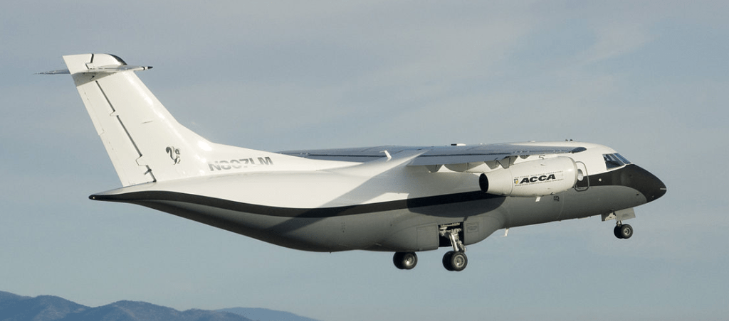
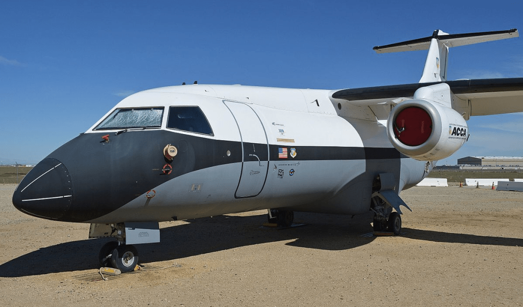
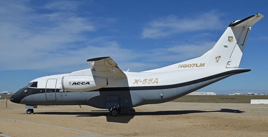
The Lockheed Martin X-55 Advanced Composite Cargo Aircraft (ACCA) is an experimental twinjet transport aircraft. It is intended to demonstrate new air cargo-carrier capabilities using advanced composite materials. A project of the United States Air Force’s Air Force Research Laboratory, it was built by the international aerospace company Lockheed Martin, at its Advanced Development Programs (Skunk Works) facility in Palmdale, California. The X-55 is a one-off aircraft intended to demonstrate the use of advanced composite materials in the fuselage of an otherwise conventional high-wing transport aircraft.
The aircraft is powered by two Pratt & Whitney Canada PW306B turbofans. The X-55 design is based on the existing Fairchild Dornier 328JET. The fuselage of that aircraft, which is constructed of aluminium alloys, was replaced aft of the entrance door with a newly designed fuselage. The new design makes extensive use of advanced composite materials, selected to allow out of autoclave curing at lower temperatures and pressures than previous materials. The new widened fuselage allows the loading of cargo through a rear ramp.
The new fuselage section is constructed as a single large component, including the vertical stabilizer. When attached to the existing nose section, the fuselage is 55 feet (16.8 m) long and 9 feet (2.74 m) diameter. The fuselage has upper and lower halves, each with a roughly-oval shape similar to a canoe. The halves are bonded to circular frames. The fuselage section ahead of the entrance door consists of the existing (metal) 328J component, with fasteners used to bring the forward and new aft sections together.
As of April 2008, the fuselage was being fabricated. The first flight of the modified aircraft was expected during the winter of 2008/2009. However, due to a “glitch” during fabricating the composite fuselage, that schedule slipped. The delay was caused by an unsatisfactory bond of the skin on the lower fuselage, which required a second fuselage to be fabricated.
The first flight was completed at Lockheed Martin’s Advanced Development Programs facility (Air Force Plant 42) in Palmdale, California on June 2, 2009 by the Air Force Research Laboratory in conjunction with Lockheed Martin. In October 2009, the ACCA demonstrator was designated X-55A by the USAF. Over the course of the program, 15 to 20 flights were expected.
As of September 12, 2014, the X-55 aircraft is on display at the Joe Davies Heritage Airpark in Palmdale, California.
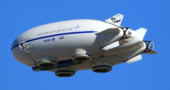
The Lockheed Martin P-791 is an experimental aerostatic and aerodynamic hybrid airship developed by Lockheed Martin. The P-791 has a tri-hull shape, with disk-shaped cushions on the bottom for landing. As a hybrid airship, part of the weight of the craft and its payload are supported by aerostatic (buoyant) lift and the remainder is supported by aerodynamic lift.
The P-791 was designed as part of the U.S. Army’s Long Endurance Multi-intelligence Vehicle (LEMV) program, but lost the program’s competition to Northrop Grumman’s HAV-3 design. The P-791 was modified to be a civil cargo aircraft under the name SkyTug, with a lift capability of 20 short tons (18,000 kg) and plans to scale larger.
The first flight of the P-791 took place on 31 January 2006 at the company’s flight test facility at United States Air Force Plant 42 in Palmdale, CA.
In March 2016, Straightline Aviation signed a Letter of intent for 12 LMH1 airships, valued at $480 million.
In 2014, Hybrid Enterprises from Atlanta, Georgia entered into an agreement with Lockheed Martin to market and sell the commercial LMH-1 Hybrid Aircraft built by Lockheed, based on the technology demonstrated by the P-791.
At the Paris Air Show in June 2015, Lockheed Martin announced that all required FAA certification planning steps were complete, and Hybrid Enterprises was accepting orders. The LMH1 would initially transport 20 tonnes of cargo or 19 passengers, plus 2 crew members, with deliveries beginning in 2018. In September 2016, plans were announced to operate the LMH-1 craft in Alaska.
In September 2017 it was announced that the first flight of the LMH-1 was being delayed to 2019.
In May 2023, Lockheed Martin announced the transfer of intellectual property and assets related to their airship business, and the LMH-1, to a new company, called AT2 Aerospace, which would continue the development of the LMH-1 as the Z1 hybrid airship.
The Lockheed Martin LMZ1M is the follow on to the P-791 test vehicle.
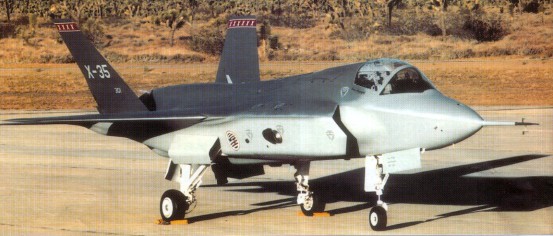
The X-35 was the Lockheed Martin Joint Strike Fighter (JSF) demonstrator, competing with the Boeing X-32. In November 1996 Boeing and Lockheed Martin were awarded contracts to build two Concept Demonstrator Aircraft (CDA)—one Conventional Take-Off and Landing (CTOL) version and one Short Take-Off and Vertical Landing (STOVL) version—each. The aircraft were not intended to be fighter prototypes, but rather to prove that the selected design concepts would work, hence the use of X-series designations.
Lockheed constructed two prototypes for the evaluation. The initial X-35A reflected the basic Air Force CTOL design, and was used for early flights before being modified into the STOVL version, designated X-35B. While Boeing proposed a direct lift STOVL design based on that used in the Harrier, Lockheed opted for a different approach in meeting the vertical flight requirements. Inspired by the Russian Yak-141, the X-35B incorporated a separate lift-fan that was shaft-driven by the F119 engine, allowing cooler exhaust temperatures during hover. While the Boeing design was more conventional, Lockheed argued that their strategy was better in the long term since it offered more room for growth as the aircraft evolves. The second airframe was the X-35C STOVL demonstrator for the Navy. This model featured an enlarged wing of greater span and area for larger fuel capacity as well as enlarged horizontal tails and flaperons for greater control effectiveness during low-speed carrier approaches. The X-35 was selected as the winner of the JSF competition on 26 October 2001.
The production aircraft to be designated F-35. The System Development and Demonstration (SDD) phase of the F-35 JSF program started with the signing of the SDD contract in October 2001, and with the delivery of test aircraft scheduled to begin in 2008. During the SDD phase, 22 aircraft (14 flying test aircraft and 8 ground-test aircraft) were to be produced and tested. The JSF program is slated to produce a total of 3,002 aircraft for the United States and United Kingdom armed forces.
Lockheed Martin leads a development team including Northrop Grumman, BAE Systems, and Pratt & Whitney. Lockheed Martin brings in advanced technology experience, stealth technology and other technologies and experience which it has gained during F-22 research and development. Northrop Grumman offers tactical aircraft knowledge, stealth technology and carrier suitability. BAE System provides expertise and experience with short take off and vertical landing (STOVL) technology as well as advanced subcontract management. Pratt & Whitney is the builder of the engine which will power the JSF which is based on the F-119 turbojet from the F-22.
To forfill the demands of the main contractors three different variants are developed. All versions will have a common structure and have the same fuselage and internal weapons bay. They will all three be powered by a F-119 modified engine. All variants will carry the standard designation F-35.
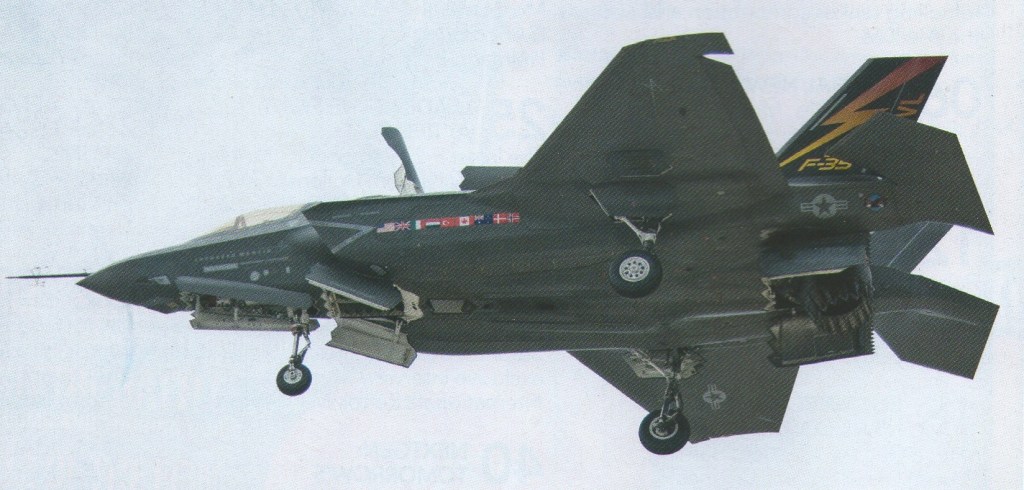
The F-35A is the standard variant with conventional take off and landing developed for the US Air Force, the biggest JSF customer. The F-35A will replace the F-16 and the A-10 aircraft currently operated by the USAF.
X-35B
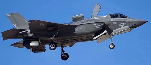
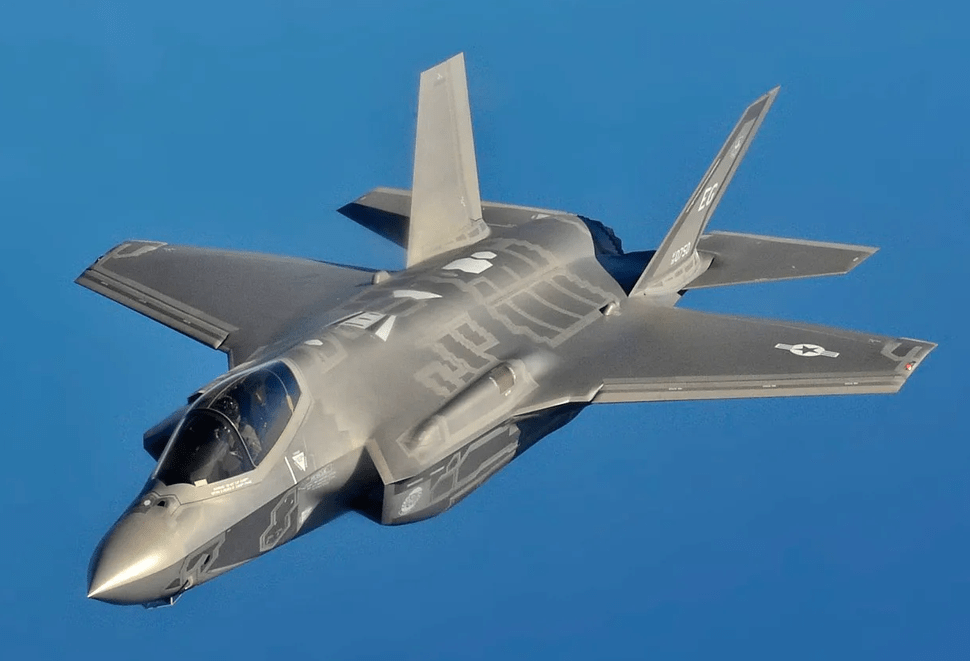
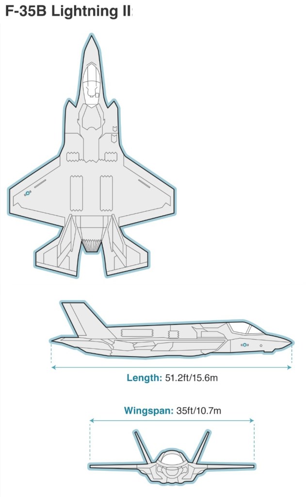
The F-35B is the STOVL variant of the JSF. The F-119 is modified using the experience of BAE Systems based on the Rolls-Royce Pegasus engine from the AV-8 Harrier. Unlike the Air Force variant the F-35B carries no internal gun and the air refuelling probe is located on the right side of the forward fuselage instead of receptacle on the top surface of the aircraft. The main customers for the F-35B will be the USMC to replace the F/A-18 Hornet ands the AV-8B Harrier IIs and the United Kingdom to replace the Royal Air Force/Royal Navy combined Harrier force of Sea Harriers and GR.7s.
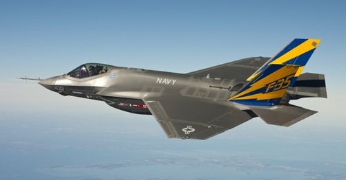
The F-35C is a modified design which enables the JSF to operate from aircraft carriers using conventional carrier landings and catapult take off. The F-35C internal structure and landing gear have been strengthened to handle the loads associated with catapult launches and arrested carrier landings. It has a larger wing area than other JSF types with larger control surfaces for better low speed handling. Like the F-35B is has a refuelling probe instead of a receptacle. The US Navy will be the biggest customer of this variant. The F-35C will complement the US Navy fleet of F/A-18E/F fighters by replacing the F/A-18 A+ and C Hornet in service.
Lockheed Martin F-35B Lightning II BF-3 – the third example of the short takeoff/ vertical landing version – arrived at NAS Patuxent River, Maryland on February 17, 2010. It made its first flight on February 2 at Fort Worth, Texas and was taken from there to the naval air station by F-35 Test Pilot Jeff Knowles. Another two F-35Bs are due to join the three aircraft at Patuxent River for the flight test programme.
The F-35B was about to conduct its first vertical landing which would be a major milestone for the short take-off, vertical landing (STOVL) variant and work has started on the first F-35 lightning II for the UK.
The Lockheed Martin X-35C Joint Strike Fighter (JSF) Navy demonstrator completed medium-speed taxi testing Dec. 14 2000 at Palrndale, California, in preparation for first flight as early as Dec. 16. The aircraft, with a larger wing and control surfaces than the X-35A, will undergo about 20 hr. of flight test at Edwards AFB, before being flown to NAS Patuxent River, Md., for the continuation of demonstrations. Meanwhile, Boeing has completed structural mode interaction testing on the X-32B short takeoff and vertical landing demonstrator, expected to fly during the first quarter of 2001. The Boeing X-32A demonstrator completed government-required Navy demonstrations Dec. 2, 2000.
First flown on 24 October 2000, the JSF X-35A demonstrator aircraft completed a highly successful flight-test programme in August 2001, and the following October the US Government awarded its development contract to Lockheed Martin over the other contender, Boeing. The lift system uses a counter-rotating lift fan, located behind the cockpit and connected to the engine by a drive shaft, as a primary lifting force. The fan produces more than 18,000 lbs of cool thrust in hover flight, with an additional 18,000 lbs coming from the main engine’s vectored aft nozzle and wing roll-posts. The shaft driven Rolls-Royce lift fan amplifies engine thrust and reduces exhaust temperature and velocity during STOVL operations. First flown on 24 June 2001, in 2001 the X-35A, reconfigured as the STVOL X-35B, achieved its first vertical take-off, level supersonic flight, and vertical landing. The X-35C is to evaluate manoeuvering qualities, as a conventional carrier version and first flew on 16 December 2000. This version has larger wing and control surfaces and is stressed for catapult launches and arrested landings. This wing could also be applied to the B or A version.
By March 2010, it appeared that just five F-35s had flown: F-35A AA-01 on December 25, 2006. F-35B BF-0 1 on June 11, 2008. F-35B BF-02 on February 2, 2009 F-35A AF-01 on November 14,2009 F-35B BF-03 on February 2, 2010
The first F-35A has since been retired from flight duty. Two of the three F-35Bs were at Naval Air Station Patuxent River, Maryland, for preliminary STOVL evaluation tests.
The first pre-production F-35A flew on 15 December 2006, about three months behind schedule due to engine integration and ground testing delays.
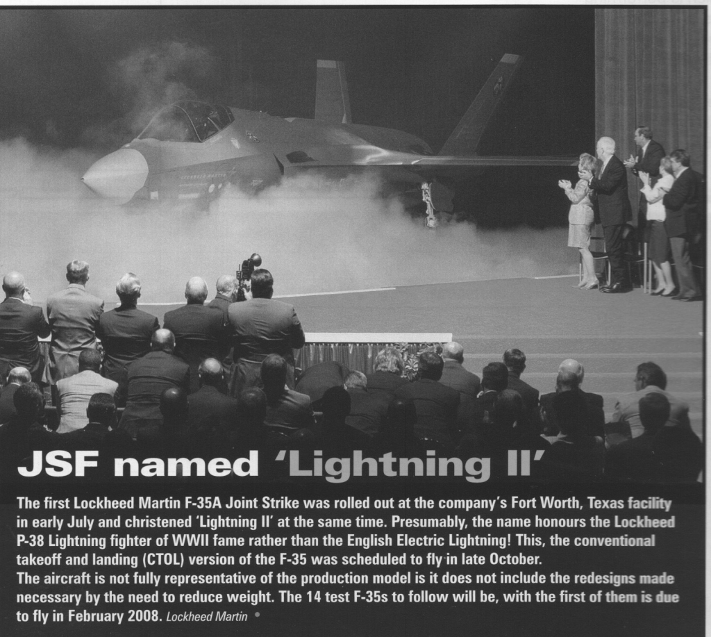
F-35 Lightning II
As of 2014, 115 have been built at $106,000,000 each.
With over 1,000 aircraft delivered to 17 nations, including Australia, Israel, Japan, South Korea, and multiple NATO allies, and production plans exceeding 3,000 units, the F-35 represents the standardisation of fifth-generation technology across Western and allied air forces.
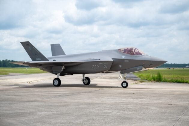
The U.S. Air Force’s 500th F-35A Lightning II fighter jet arrived at the Florida Air National Guard’s 125th Fighter Wing in Jacksonville on July 9, 2025.
500th USAF F-35A Lightning II
The aircraft is one of the first three F-35As permanently assigned to the wing, known as “the Thunder,” and features the unit’s legacy tail flash. By the end of 2024, Lockheed Martin had delivered a total of 1,102 aircraft. That figure included 797 F-35As built for the United States and allied air forces, along with 203 short takeoff and vertical landing F-35Bs built for the U.S. Marine Corps, the Royal Navy, the Royal Air Force, and the Italian Navy. The first examples for Japan’s Navy are also in production and delivery. According to F35.com, more than 1,215 F-35s of all variants have now been delivered worldwide, flown by over 3,000 pilots who have accumulated more than one million flight hours.
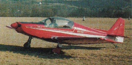
The Whisky IV is a tandem two seat, low wing aircraft designed by Giuseppe Vidor. Construction materials are wood & fabric. The landing gear is a fixed tailwheel configuration. 2009 Complete set of plans $400 (US$)
Engine: Limbach 2000, 80 hp HP range: 75-100 Wing Span: 26.25 ft. Wing Area: 120.5 sq. ft. Length: 21 ft. Height: 7 ft. Cockpit Width: 28.3 in. Aspect Ratio: 5.7 Dihedral Angle: 4° Wash Out: 1.50° Empty Weight: 622 lbs. Gross Weight: 1058 lbs. Wing Loading: 8.78 lbs./sq. ft. Power Loading: 13.22 lbs./HP C.G. Travel: 18.3 to 31% MAC Fuel Capacity: 13.2 gal. / 79 lbs. V.N.E: 175 mph. Max Horizontal Speed: 160 mph. Cruise 75% Power: 130 mph. Max Maneuvering Speed: 115 mph. Max Flap Speed: 84 mph. Stall Speed Flaps Down: 37 mph. Stall Speed Flaps Up: 43 mph. Take-Off Distance: (Solo) 330 ft. Landing Distance: (Solo) 490 ft. Fuel Burn 75% Power: 3.17 gal./hr. Max Range 75% Power: 535 nm Rate Of Climb: 785 ft./min. Service ceiling: 12,000 ft Seats: 2 tandem Landing gear: retractable tailwheel