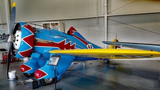
Mayocraft Inc completed construction and flight-testing of its P-26D, a near-100 percent scale tribute to the Boeing P-26 aircraft. Although not an exact replica, the aircraft is generally patterned after the famed Boeing P-26 “Peashooter”.
Mayocraft tried to be faithful not only to the overall appearance of the P-26, but also to most of the fabrication methods at the time of its manufacture. The aircraft’s all-metal skin has been hand formed and shaped in many complex compound curves by Mayo in his shop, which is in essence a small aircraft factory with tools, technology and expertise straight out of the mid-1930’s. The craft has over 29,000 3 AD rivets, inserted, driven and made flush with the skin. The craft has other parts, most of which had to be machined and fabricated from raw metal or cleverly adapted from existing aircraft parts.
Nathan Mayo devised fabrication methods like pressing into hard rubber and pull-forming sheet metal, whose results mimic those from the much larger production machines that would have been found in a 1930s-era aircraft factory.
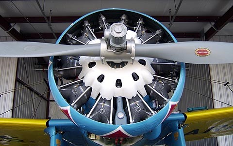
For safety and performance’s sake selected improvements were made. Alclad 2024-T3 aluminum was used throughout instead of the Dural of the 1930’s because the modern alloy is 20 percent stronger. The main landing gear wheels and brakes are adapted from a Cessna T-50. The engine exhaust is made from a stainless steel alloy specially formulated for aerospace applications. For a few non-structural elements, in place of metal they formed fiberglass. The engine and propeller are the same as employed in the T-6.
Mayo adapted a different airfoil shape to the wing that should make the bird a little easier to fly and land than the original. Mayo calculated that, because of these improvements and the fact that the Peashooter does not have the armament that was originally needed in the combat airplane, “it has a performance about 10 percent better than the original.”
The shock struts are Bendix from a Cessna UC-78 and brakes are Cleveland, 4 disk, hydraulic with an AT-6 master cylinder.
The main tires are 7.50 x 10, tail tire – 12.5 – P51 channel tread, and the tail wheel has detent & positive lock.
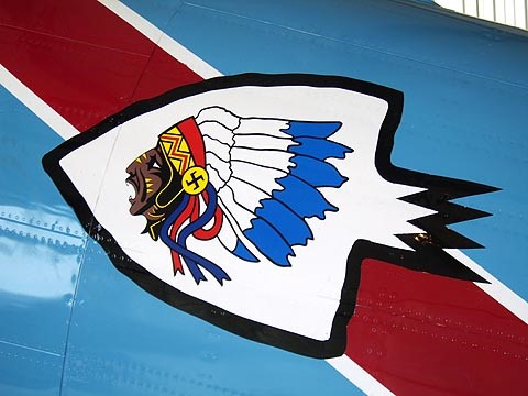
The paint scheme design was from the 1st. Pursuit Group, 94th. Squadron, Selfried Field, Michigan, circa 1935-1936, done with DuPont Imron paint.
Registered NX26PX, taxi testing commenced in September, 2006. Flight testing was completed in 2009.
The Mayocraft P-26D is now on display at the Military Aviation Museum in Virginia Beach, Virginia.
Mayocraft P26D Peashooter Scale: Near 100 percent Engine: Pratt & Whitney R-1340-AN1 Prop: Hamilton Standard 12D-40 with 6101-12 Blades Airfoil: E-193 (UIUB) Fuel capacities: Main fuselage tank: 57 gal. Each wing tank: 23 gal. Oil capacity: 9 gal. Anticipated Performance Cruise speed: greater than 210 MPH Max. initial rate of climb: more than 2500 fpm. Max. speed (VNE): 315 MPH Landing speed: 73 MPH with flaps
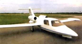
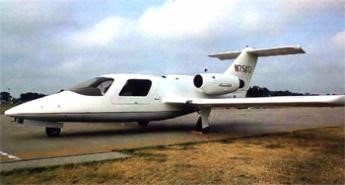
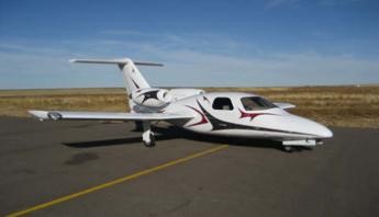
Bob Bornhofen was retired when he got into the aviation business, and had no aviation background. He wondered why he couldn’t buy a personal jet, and in 1998 he decided to create one. Bornhofen has been funding much of the project out of his own pocket.
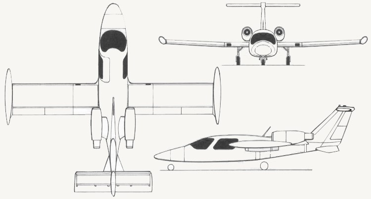
To be marketed as a kit, the Twinjet has a pre-preg eglass composite airframe with carbon fiber control surfaces and empennage.
The TwinJet was not certified because it uses two converted surplus GE-T58 military helicopter engines (overhauled and zero-timed).
The TwinJet was designed in anticipation of the FJX-2 engine, which was being developed under the General Aviation Propulsion program. The FJX-2 was going to be a new generation turbofan engine producing 700-800 pounds of thrust.
When delays occurred for that engine, Bob Bornhofen elected to use the T58 engines so he wouldn’t slow the TwinJet development.
The first prototype was flight tested to about 370 knots during a series of tests to determine if the aircraft had any major certification-related problems.
Engines: 2 x GE-T58 turbojet Wing span: 10,21 m (33 ft 6 in) Wing span, tip tanks: 10,52 m (34.5 feet) Lenth overall: 8,69 m (28 ft 6 in) Height overall: 2,74 m (9 ft 0 in) Empty weight: 2,600 lb MAUW: 5,100 lb Fuel capacity: 270 USgallon Optional fuel: 320 US gallon Max speed 30,000 ft: 480 mph Cruise speed 30,000 ft: 400 mph Single-engine cruise speed 30,000 ft: 230 mph Initial rate of climb: 3,500 fpm Single-engine climb rate: 1,000 fpm Stall at 5,100 lb: 90 mph Range standard fuel: 1,000 miles Range optional fuel: 1,300 miles
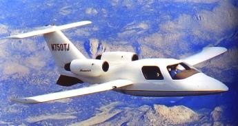
Prototype N750TJ.
Serial number: 1, First flight 4 august 1999. Public debut at EAA Air venture, Oskosh, August 2000. Destroyed on Jan. 24, 2003 in Melbourne, Florida
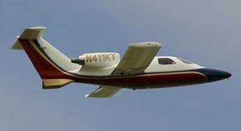
N411KT
Serial number: 2, Owned by Mike Seavall (Longmont, Colorado). It was built from a Maverick Air’s kit. Two years were spent to build it.
N699VA
Serial number: 3 Professionaly built in 2003. Fitted with 2 T850 engines
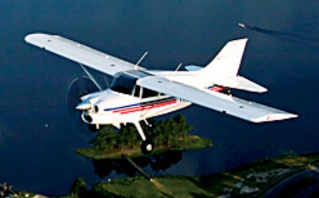
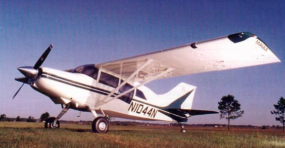
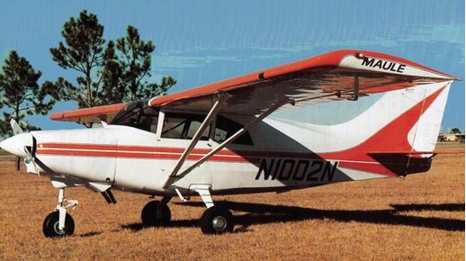
In 1981, Maule installed an IO-540-W1A5D out front of the M-5 and began delivering the M-6, also available with EDO floats. Two years later the model would morph into the M-7 and in 1989, the M-8. In 1991, the company experimented with a turbine Maule, installing an Allison 420 shp 250-B17-C and eventually offered the design in both taildragger and tricycle gear configurations. The family continues to create endless variations and improvements on the original airframe, with the original fuselage jig designed by founder B.D. Maule still in use in 1975.
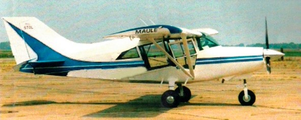
Maule Aircraft have fitted their utility aircraft with Allison 250-B17 engines to create two new models, the M-7 and MX-7. Initial performance estimates include a 196 mph cruise, a partly loaded takeoff distance of 400 feet and a gross weight climb of 3000 feet/minute.
Fuselage: 4130 Chromoly Steel truss structure Covering: Ceconite (a synthetic fabric) covers the fuselage, tail, and tail control surfaces Wing, Flap, Aileron: Aluminum Spar, ribs, and skin Firewall: Stainless Steel Engine Cowling: Fiberglass Doors: Steel frame with aluminum skin Instrument Panel: Aluminum Aircraft Interior: Fully upholstered – standard vinyl/velour seats and trim, velour headliner Fuselage and tail structures are powder-coated for corrosion resistance. Wing lift struts are sealed and internally coated with oil. Wings, flaps, and ailerons are primed inside and out for corrosion resistance. Urethane primer and finish paint used to provide long-lasting beauty, protection, and flexibility for the Ceconite covering. Optional Stainless Steel Kit – This kit provides SS bolts where approved. SS turnbuckles for elevator (Ref. SL#55), SS clevis pins for control surfaces
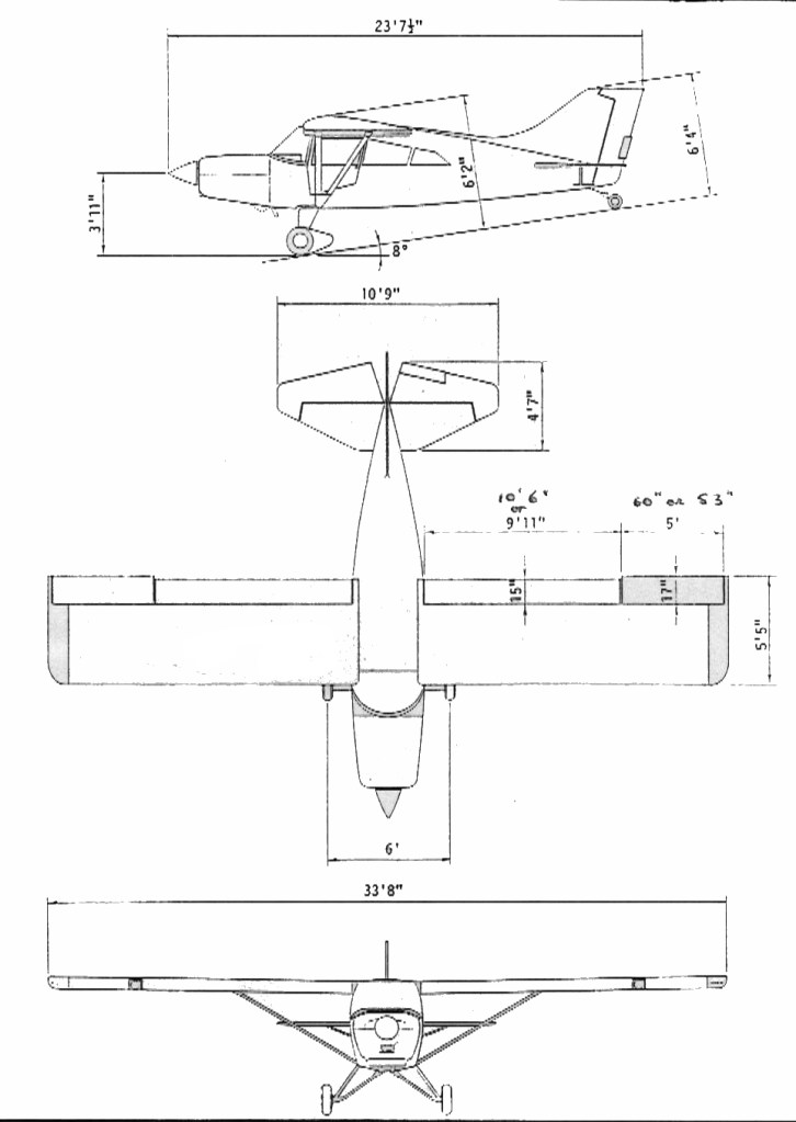
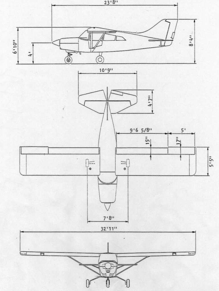
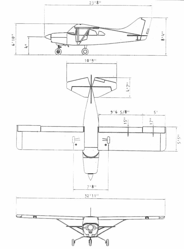
M-7-235C Engine: Lycoming IO-540-WIA5, 235 hp TBO: 2000 hr Propeller: Const. spd. Wing Span: 32 ft 11 in Wing Area: 165.6 sq ft Length: 23 ft 6 in Height: 6 ft 4 in Gross weight: 2500 lb Empty weight: 1600 lb Fuel: 73 USgal Baggage capacity: 250 lb Landing gear type: Conv./Fixed Gear Width: 7 ft 10 in Cruise speed 75% power: 124 kt Cruise speed 65% power: 116 kt Max range (w/ reserve) 75% power: 572 nm Max range (w/ reserve) 65% power: 542 nm Stall speed (gear, flaps down): 39 kt Fuel consumption 75% power: 13 USgph Fuel consumption 65% power:12.5 USgph Flap Settings: -7, 0, 24, 40, 48 degs Best Climb Speed: 90 mph Best rate of climb: 1150 fpm Service ceiling: 20,000 ft Seats: 5 Cabin Width Front Seats: 42” shoulder, 37” hips Cabin Width Pass. Seats: 38” shoulder, 34” hips Cabin Width Rear Pass Seat: 33” shoulder, 28” hips Cabin height: 37 in Takeoff ground roll: 450 ft Landing ground roll: 550 ft
M-7-260 Wing Span: 32 ft 11 in Wing Area: 165.6 sq ft Length: 23 ft 6 in Height: 6 ft 4 in Flap Settings: -7, 0, 24, 40, 48 degs Best Climb Speed: 90 mph Seats: 5 Cabin Width Front Seats: 42” shoulder, 37” hips Cabin Width Pass. Seats: 38” shoulder, 34” hips Cabin Width Rear Pass Seat: 33” shoulder, 28” hips
M-7-260C Engine: Lycoming IO-540-V4A5, 260 hp TBO: 2000 hr Fuel type:100LL Propeller: 78/79.5 Inch (2 Blade) 78/80 (3 Blade) Landing Gear Configuration: Spring Gear Wing Span: 32 ft 11 in Wing Area: 165.6 sq.ft Length: 23 ft 6 in Height: 8 ft 4 in Wing loading: 9.6 lb/sq. ft Power loading: 15 lb/hp Cabin Width Front Seats: 42” shoulder, 37” hips Cabin Width Pass. Seats: 38” shoulder, 34” hips Cabin Width Rear Pass Seat: 33” shoulder, 28” hips Cabin height: 46 in Cabin doors: 4 Baggage capacity: 170 lb Seats: 5 Max ramp weight: 2500 lb Gross Weight: 2500 Pounds Landing weight: 2500 lb Empty Weight: 1671 Pounds Useful Load: 829 lb Useful Fuel Capacity: 73 Gal. Stall Speed (Full Flaps/1 Person/ 1/2 Fuel: 40 mph. Rate Of Climb (1 Person/ 1/2 Fuel): 2000 fpm Land at Gross Over 50′ Obstacle: 500 Feet Best Climb Speed: 90 Mph. Service Ceiling: 20,000 Feet Fuel consumption 75% power: 15.0 USgph Fuel consumption 65% power: 13.5 USgph Range, Max (30 Minute Reserve): 782 Miles Cruise (75% Power at Opt. Alt.): 166 Mph. Landing gear type: Fixed/Conv Wheel base: 7 ft 10 in Wheel track: 15.8 ft Wheel size, std: 7.00 x 6 in Flap Settings: -7, 0, 24, 40, 48 degs Takeoff ground roll: 250 ft Takeoff over 50-ft. obstacle: 600 ft Landing ground roll: 300 ft Landing over 50-ft. obstacle: 500 ft
M-7-420 Wing Span: 32 ft 11 in Wing Area: 165.6 sq ft Length: 23 ft 6 in Height: 6 ft 4 in Flap Settings: -7, 0, 24, 40, 48 degs Best Climb Speed: 90 mph Seats: 5 Cabin Width Front Seats: 42” shoulder, 37” hips Cabin Width Pass. Seats: 38” shoulder, 34” hips Cabin Width Rear Pass Seat: 33” shoulder, 28” hips
M-7-420AC Wing Span: 33 ft 8 in Wing Area: 169.2 sq ft Length: 24 ft Height: 6 ft 4 in Gear Width: 7 ft 10 in Flap Settings: -7, 0, 24, 40, 48 degs Best Climb Speed: 90 mph Seats: 5 Cabin Width Front Seats: 42” shoulder, 37” hips Cabin Width Pass. Seats: 38” shoulder, 34” hips Cabin Width Rear Pass Seat: 33” shoulder, 28” hips
M-7-235/260/420
Maule MT-7
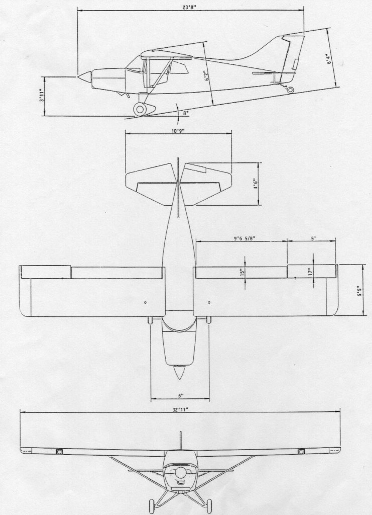
MT-7-235 Engine: Lycoming IO-540-W1A5D Landing Gear Configuration: TriGear Wing Span: 32 ft 11 in Wing Area: 165.6 sq.ft Length: 23 ft 6 in Height: 8 ft 4 in Cabin Width Front Seats: 42” shoulder, 37” hips Cabin Width Pass. Seats: 38” shoulder, 34” hips Cabin Width Rear Pass Seat: 33” shoulder, 28” hips Seats: 5 Gross Weight: 2500 Pounds Empty Weight: 1625 Pounds Useful Load: 875 Pounds Fuel Capacity: 70 Gal. Stall Speed (Full Flaps/1 Person/ 1/2 Fuel: 40 mph. Take Off (1 Person/ 1/2 Fuel): 200 Feet Take Off at Gross Over 50′ Obstacle: 600 Feet Rate Of Climb (1 Person/ 1/2 Fuel): 1700 fpm Land at Gross Over 50′ Obstacle: 500 Feet Best Climb Speed: 90 mph Service Ceiling: 20,000 Feet Fuel Consumption (65% Power): 12 USGPH Range, Max (30 Minute Reserve): 850 Miles Cruise (75% Power at Opt. Alt.): 160 mph. Gear Width: 7 ft 8 in Flap Settings: -7, 0, 24, 40 degs
MT-7-260 Engine: Lycoming IO-540-V4A5 Landing Gear Configuration: TriGear Wing Span: 32 ft 11 in Wing Area: 165.6 sq.ft Length: 23 ft 6 in Height: 8 ft 4 in Cabin Width Front Seats: 42” shoulder, 37” hips Cabin Width Pass. Seats: 38” shoulder, 34” hips Cabin Width Rear Pass Seat: 33” shoulder, 28” hips Seats: 5 Gross Weight: 2500 Pounds Fuel Capacity: 73 USGal. Stall Speed (Full Flaps/1 Person/ 1/2 Fuel: 42 Mph. Take Off (1 Person/ 1/2 Fuel): 200 Feet Take Off at Gross Over 50′ Obstacle: 600 Feet Rate Of Climb (1 Person/ 1/2 Fuel): 1350 FPM (Gross) Land at Gross Over 50′ Obstacle: 500 Feet Best Climb Speed: 90 Mph Service Ceiling: 20,000 Feet Cruise (75% Power at Opt. Alt.): 167 Mph. Flap Settings: -7, 0, 24, 40 degs Best Climb Speed: 90 mph
MT-7-420 Engine: Allison 250-B17 Wing Span: 32 ft 11 in Wing Area: 165.6 sq ft Length: 24 ft 6 in Height: 8 ft 4 in Landing Gear Configuration: TriGear Gear Width: 7 ft 8 in Flap Settings: -7, 0, 24, 40 degs Best Climb Speed: 90 mph Seats: 5 Cabin Width Front Seats: 42” shoulder, 37” hips Cabin Width Pass. Seats: 38” shoulder, 34” hips Cabin Width Rear Pass Seat: 33” shoulder, 28” hips Fuel Capacity: 85 US gal
MT-7-235/260/420
Maule MX-7
MX-7-160 Engine: Lycoming O-320-B2D Propeller: Sensenich 74 Inch Landing Gear Configuration: Oleo Strut Taildragger Wing Span: 32 ft 11 in Wing Area: 165.6 sq ft Length: 23 ft 6 in Height: 6 ft 4 in Cabin Width Front Seats: 42” shoulder, 37” hips Cabin Width Pass. Seats: 38” shoulder, 34” hips Seats: 4 Gross Weight: 2200 Pounds Empty Weight: 1330 Pounds Useful Load: 870 Pounds Fuel Capacity: 40 Gallons (70 optional) Stall Speed (Full Flaps/1 Person/ 1/2 Fuel: 40 Mph. Take Off (1 Person/ 1/2 Fuel): 600 Feet Take Off at Gross Over 50′ Obstacle: 1180 Feet Rate Of Climb (1 Person/ 1/2 Fuel): 825 FPM Land at Gross Over 50′ Obstacle: 500 Feet Best Climb Speed: 90 Mph. Service Ceiling: 13,000 Feet Fuel Consumption (65% Power): 8 USGPH Range, Max (30 Minute Reserve): 540 Miles Cruise (75% Power at Opt. Alt.): 135 Mph. Gear Width: 6 ft Flap Settings: -7, 0, 24, 40, 48 degs
MX-7-180A Engine: Lycoming O-360-C1F/-C4F Propeller: Sensenich 76 Inch Landing Gear Configuration: Oleo Strut Taildragger Wing Span: 32 ft 11 in Wing Area: 165.6 sq ft Length: 23 ft 6 in Height: 6 ft 4 in Cabin Width Front Seats: 42” shoulder, 37” hips Cabin Width Pass. Seats: 38” shoulder, 34” hips Seats: 4 Gross Weight: 2400 Pounds Empty Weight: 1350 Pounds Useful Load: 1050 Pounds Fuel Capacity: 40 Gallons (70 optional) Stall Speed (Full Flaps/1 Person/ 1/2 Fuel: 40 Mph. Take Off (1 Person/ 1/2 Fuel): 550 Feet Take Off at Gross Over 50′ Obstacle: 1150 Feet Rate Of Climb (1 Person/ 1/2 Fuel): 920 FPM Land at Gross Over 50′ Obstacle: 500 Feet Best Climb Speed: 90 Mph. Service Ceiling: 15,000 Feet Fuel Consumption (65% Power): 9 USGPH Range, Max (30 Minute Reserve): 500 Miles Cruise (75% Power at Opt. Alt.): 140 Mph. Gear Width: 6 ft Flap Settings: -7, 0, 24, 40, 48 degs
MX-7- 180B Engine: Lycoming O-360-C1F Propeller: Sensenich 76″ Landing Gear Configuration: Oleo Strut Taildragger Wing Span: 32 ft 11 in Wing Area: 165.6 sq.ft Length: 23 ft 6 in Height: 6 ft 4 in Cabin Width Front Seats: 42” shoulder, 37” hips Cabin Width Pass. Seats: 38” shoulder, 34” hips Seats: 4-5 Gross Weight: 2500 Pounds Empty Weight: 1395 Pounds Useful Load: 1105 Pounds Fuel Capacity: 73 USGal. Stall Speed (Full Flaps/1 Person/ 1/2 Fuel: 40 mph Take Off (1 Person/ 1/2 Fuel): 300 Feet Take Off at Gross Over 50′ Obstacle: 600 Feet Rate Of Climb (1 Person/ 1/2 Fuel): 1200 FPM Land at Gross Over 50′ Obstacle: 500 Feet Best Climb Speed: 90 mph. Service Ceiling: 15,000 Feet Fuel Consumption (65% Power): 9 USGPH Range, Max (30 Minute Reserve): 1095 Miles Cruise (75% Power at Opt. Alt.): 145 Mph. Gear Width: 6 ft Flap Settings: -7, 0, 24, 40, 48 degs
MX-7-180AC Wing Span: 32 ft 11 in Wing Area: 165.6 sq ft Length: 23 ft 6 in Height: 6 ft 4 in Gear Width: 7 ft 10 in Flap Settings: -7, 0, 24, 40, 48 degs Best Climb Speed: 90 mph Seats: 4 Cabin Width Front Seats: 42” shoulder, 37” hips Cabin Width Pass. Seats: 38” shoulder, 34” hips
MX-7-180C Engine: Lycoming: O-360-C1F Propeller: 76 Inch Landing Gear Configuration: Spring Gear Wing Span: 32 ft 11 in Wing Area: 165.6 sq ft Length: 23 ft 6 in Height: 6 ft 4 in Cabin Width Front Seats: 42” shoulder, 37” hips Cabin Width Pass. Seats: 38” shoulder, 34” hips Configuration: 4-5 Gross Weight: 2500 Pounds Empty Weight: 1500 Pounds Useful Load: 1000 Pounds Fuel Capacity: 73 Gal. Stall Speed (Full Flaps/1 Person/ 1/2 Fuel: 40 Mph. Rate Of Climb (1 Person/ 1/2 Fuel): 1200 FPM Land at Gross Over 50′ Obstacle: 500 Feet Best Climb Speed: 90 Mph. Service Ceiling: 15,000 Feet Fuel Consumption (65% Power): 9 GPH Range, Max (30 Minute Reserve): 1095 Miles Cruise (75% Power at Opt. Alt.): 145 Mph. Gear Width: 7 ft 10 in Flap Settings: -7, 0, 24, 40, 48 degs
M-7-235 Engine: 235-hp Lycoming O-540-J3A5 Seat 4-5 Gross wt. 2,500 lb Empty wt. 1,500 lb Fuel capacity 40-70 USG Cruise 148 kts Stall 40 kts Initial climb rate 1,350 fpm Range 478 miles Ceiling 20,000 ft Takeoff distance (50′) 600 ft Landing distance (50′) 600 ft
MX-7-235B Wing Span: 32 ft 11 in Wing Area: 165.6 sq ft Length: 23 ft 6 in Height: 6 ft 4 in Gear Width: 6 ft Flap Settings: -7, 0, 24, 40, 48 degs Best Climb Speed: 90 mph Seats: 4 Cabin Width Front Seats: 42” shoulder, 37” hips Cabin Width Pass. Seats: 38” shoulder, 34” hips
M-7-235C Engine: Lycoming: O-540-J3A5, O-540-B4B5, IO-540-W1A5 Propeller: 81/80 Inch (2/3 Blade) Landing Gear Configuration: Spring Gear Wing Span: 32.9 Feet Wing Area: 165.6 Square Feet Length: 23.5 Feet Height: 6.3 Feet Cabin Width: 42 Inches Configuration: 5 Place Gross Weight: 2500 Pounds Empty Weight: 1600 Pounds Useful Load: 900 Pounds Fuel Capacity: 73 Gal. Stall Speed (Full Flaps/1 Person/ 1/2 Fuel: 40 Mph. Rate Of Climb (1 Person/ 1/2 Fuel): 1800 FPM Land at Gross Over 50′ Obstacle: 500 Feet Best Climb Speed: 90 Mph. Service Ceiling: 20,000 Feet Fuel Consumption (65% Power): 11 (IO) USGPH / 12 (O) USGPH Range, Max (30 Minute Reserve): 935 Miles Cruise (75% Power at Opt. Alt.): 160 Mph. Gear Width: 6 ft Flap Settings: -7, 0, 24, 40, 48 degs
MX-7-260 Wing Span: 32 ft 11 in Wing Area: 165.6 sq ft Length: 23 ft 6 in Height: 6 ft 4 in Gear Width: 7 ft 8 in Flap Settings: -7, 0, 24, 40, 48 degs Best Climb Speed: 90 mph Seats: 4 Cabin Width Front Seats: 42” shoulder, 37” hips Cabin Width Pass. Seats: 38” shoulder, 34” hips
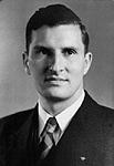
Belford D. Maule, or “B.D.”, as everyone knew him, was born November 4, 1911 in Old Fort, Ohio to farming parents. Not caring much for farm life, he left at the age of 15 to live in Salladasburg, PA. with an uncle and aunt who owned a garage and tea room. There he demonstrated his mechanical ability by building a tractor, and by motorizing an ice cream freezer and an ice saw, among other things.
B.D. joined the Army when he was 18 and was assigned to the 19th Airship Company at Langley Field, Virginia. While working on dirigibles, he found time to design and build his first airplane, a single seat midwing monoplane powered by a Henderson 27 HP motorcycle engine, known as the M-1. Starting with the airplane on floats, and later on wheels at the Salladasburg farm, B.D. taught himself to fly. (Regulations weren’t as strict in those days.)
Following his stint in the Army, B.D. moved back to Pennsylvania and became a family man, marrying June Aderhold in 1934. June and B.D. located in Jersey Shore, Pennsylvania and built their own home there in 1936. Note that Jersey Shore is not only June’s birthplace but is also midway between Lock Haven (Piper Aircraft) and Williamsport (Lycoming Aircraft Engines). This was an area in keeping with B.D.’s interest in aviation. B.D. went to work for Lycoming, and in 1939 designed and built “the Hummer”, a low cost mechanical starter for light aircraft. (Many airplanes did not have electrical systems back then.) In 1940, the Maule family moved to Jackson, Michigan. Mechanical Products Company was formed to manufacture the Hummer starter (Piper and the Continental Engine Company had shown an interest). In 1941 the B.D. Maule Company was formed in Napoleon, Michigan to build a light aircraft tailwheel which B.D. had designed. The steerable, full-swiveling tailwheel, is still being manufactured by Maule, in an improved form. With the advent of World War II, the starter business waned, and tailwheels were in demand as well as subcontract work to support the war effort.
As a diversion during the latter part of the war, B.D. designed a man-powered glider with flapping wings, known as an ornithopter. He claims to be the first (and is probably the last) person to have successfully flown such a device.
In 1946, B.D. and June purchased a farm near Napoleon, Michigan. With the help of their two oldest children, they converted it to an airport. In the process, they had the dubious honor of leveling a dog race track which had been operated by Al Capone. The airport flourished, being used for flight training during the initial post-war aviation boom.
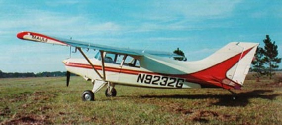
Maule Aircraft Corporation formed by B. D. Maule at Jackson, Michigan, to manufacture M-4 four-seat light aircraft; production transferred to Moultrie, Georgia, September 1968. The airplane manufacturing business that received its first FAA type certificate in 1961. Prototype flown September 8, 1961, produced as M-4 with 145 hp Continental engine, as M-4 Rocket with 210 hp Continental. M-4 Strata-Rocket with Franklin engine led to M-5-220C Lunar Rocket, flown 1 November 1971, while M-4 Rocket became M-5-210C; M-5- 235 with 235 hp Lycoming 0-540 engine also built. Current name Maule Air Inc., offering large range of four- and five-seat lightplanes for recreational and business uses in the M-7, MT-7 and MXT-7 series. Over 2,000 Maule aircraft built since 1961.
The Maules are built on the Air Force’s abandoned Spence Air Base, just east of Moultrie, Georgia. They had been building airplanes for years in Jackson, Michigan, when in 1972, a particularly severe winter convinced them to seek a warmer haven. Moultrie was looking for industry. The first production model, known as the Jetasen M-4 was delivered in April 1962. Then, as now, all Maules are constructed in Moutrie, Georgia.
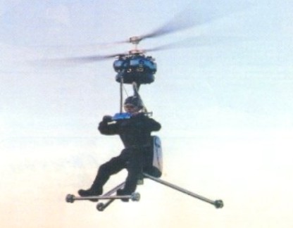
A single-seat strap-on helicopter. Complete helicopter fitted with one five-USG fuel tank and flown in the ultralight category. Gen H-4 should take 30-40 hours to assemble. Kit: $36,000 in 2009.
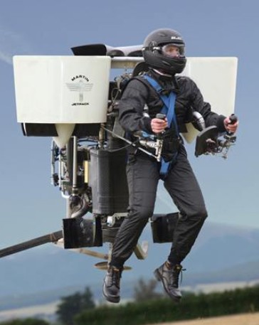
Oshkosh, Wisconsin, 2008, was the launch pad for a world first in personal flight today when Martin Aircraft Company unveiled the ultimate personal flying machine – the Martin Jetpack. Glenn Martin, Inventor of the Martin Jetpack and Managing Director of Martin Aircraft Company, showed the world that sustainable personal flight is now possible.
Glenn has devoted almost 30 years to the research and development of the Martin Jetpack. Glenn and a group of avionic, technical, design and production experts at Martin Aircraft Company have created a jetpack that flies 100 times longer than its predecessor the Bell Rocket Belt.
The Martin Jetpack has a patented fan jet technology, uses regular gasoline, complies with Ultralight regulations and is easy to fly after completion of a unique training program.
In 2005, Prototype 9 achieved sustained flight times, laying the foundation for a viable and successful pre-production prototype to be developed. In 2008 the Martin Jetpack was launched.
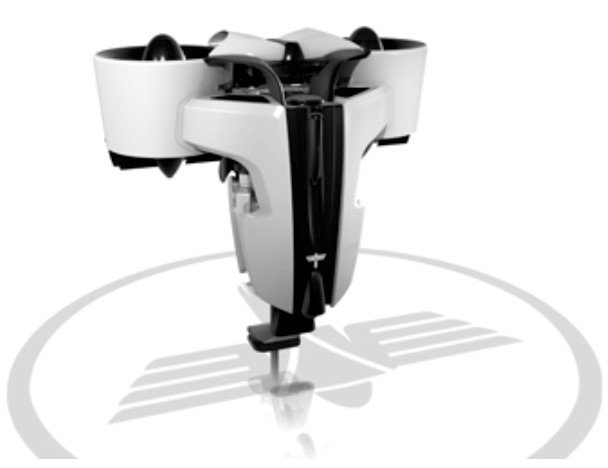
The core of this machine is the fan, its duct and the flow straighteners. These have cost the team countless hours as they pushed the boundaries of the science of ducted fans in a low speed environment. Mr Martin found that while many of the ‘facts’ older designs were based on were as solid as the day they were first committed to the text book, others were due either to the originators trying to simplify the calculations because of a lack of modem processing power, or had a fudge factor to cover steps in the process that didn’t become clear until high quality CFD systems were available.
A long series of experiments with Solidworks 3D CAD-drawn concepts run through CFD (a computer based simulation of a wind tunnel) brought about a series of promising steps forward in efficiency that were checked out on the workshop test rig. The team now have a fan blade that is not only light at roughly 100gm per blade, it also runs at 92 percent efficiency. The best Mr Martin can find elsewhere is the lift fans on the JSF which are published at 87 percent. The team have also worked hard to get the whole ducted fan package efficient across a broad speed range. The 2011 setup has a relatively flat efficiency curve with a small peak at around 60 km/h forward speed. Each fan unit is considered to be torque neutral which means the airflow from the duct is so close to straight that the twist is almost immeasurable, giving gains in thrust.
The fans needed a light, unobtrusive and reliable drive method which led the team to the modem synchronous belt. The latest designs have carbon fibre tensile cord inside the polyurethane belt with nylon facing on the teeth. The power transfer for width is better than for chain and challenges many gear-driven alternatives especially on weight. The major requirement for belts is to keep an alignment of better than half a degree and constant tension. Most belt drives use aluminium housings which shrink and grow with ambient temperatures let alone engine temperatures, so the decision was taken to go to a carbon fibre structure to all but eliminate temperature related dimension changes. The carbon structure also greatly assisted in keeping the alignment within spec.. The final touch was to make sure the drive and driven pulleys were fully supported by bearings on either side: no poor quality over hung shafts would be allowed in this design.
Once the horsepower requirements of the fans were known, a search of all known production engines was made. Power density, brake specific fuel consumption, package size and reliability were recorded, then checked against the requirements. No production engine had the power to weightt ratio needed allied with the high reliability the team demanded. Martin Aircraft sought advice from various companies and found that marine applications, such as outboards, shared many of the operational needs of the aviation world. Both users tend to run at three settings: idle; around 75% continuous; and 100% for extended periods. With this in mind, questions were asked of one specialist, Mercury Marine, to ascertain the level of stress an engine could be placed under and still achieve high reliability. The end result was four gentlemen For reliability and packaging reasons a water cooled V4 two-stroke was chosen. This gives a power pulse every 90 degrees which brings the peak and mean torque at the crankshaft nice and close together, resulting in a smooth output to the fans. To further smooth the power delivery, there is a ‘centre flex’ type rubber coupling before the drive enters the c!rive pulley. The cylinders are from Honda (CR 500 motor crosser), modified by replacing the steel sleeves with aluminium coated with nikasil. The change gives better heat transfer and reduces the engine weight by over 3kg. New heads have been made which have a carbon fibre top cover to keep the water in and the weight down.
The exhaust system is a simple yet brilliant piece of work which through its various interconnections and pipe lengths gives a lesser improvement at peak rpm compared to a full expansion chamber system, but functions well over a very wide band. The torque curve is one of the flattest I’ve seen, which means the horsepower line has no real humps or hollows as the rpm rise. Reliability is vital in a machine that has no wings (just a BRS ‘chute fitted) so the engine team have incorporated all the hallmarks of a reliable engine such as mean piston speeds below 15m/s, bore and stroke ratio kept below 1.15 / 1, and porting size and shape designed to protect the rings as they pass. All based on hard-won data from the marine industry where after tens of thousands of engines they have learnt a thing or two.
The cooling system has a neat (and patented) method of pumping air through the radiator. To understand it, think about blowing air across the top of a milk bottle. The airflow from your breath across the top creates a draw on the air in the milk bottle. The horizontally mounted radiator on thej etpack has ducts that sit on the side of the entry to the ducted fans so that the rush of air going into the fans pulls air through the radiator. The more horsepower applied the more airflow through the fans and therefore more flow through the cooling system. Another simple yet brilliant design.
The first prototype Jetpacks were manually controlled and apparently not hard to fly, but the team have their eye on a market where a high level of automation seems preferable. The fully fly-by-wire system uses the same unit as the Predator UAV for its air speed, gyro, magnometer, GPS and other critical inputs, but the processing and control is done by a dual redundant Martin Aircraft system. When creating it the team were helped immensely by a professor from Bremen University who joined for six months to apply his experience in control systems. He also helped with the creation of a proper flight simulator suitable for training and checking out software changes to the real thing. The fly-by-wire approach allows the operator to simply command the machine to rise or fall, turn left or right, leaving the control units to move the duct vanes and the cruciform, surfaces in the jetstrearn to create directional change while changing the engine output to control height and speed.
Release the controls at any time and the system will maintain height and gradually bring you back to stable hover.
Martin Aircraft has created a concept, not just a one-off machine. The current version suits US Part 103 rules, so it is limited in overall weight, speed and fuel capacity. Accepting these limitations opens up a large private market for the Jetpack. A slightly bigger ‘unregulated ‘ version on the same basic configuration can lift 200kg-plus payloads versus the current 115 kg and stay aloft for over 90 minutes. Still bigger versions exist on paper.
The 12th prototype featured a 200 hp V-4 engine driving two ducted fans. It had been flown to more than 3000 ft and 74 kph. The planned price at that stage was US$150,000 to US$250,000.
Standard Equipment: Flight and Engine displays Harness Ballistic Parachute Retractable undercarriage Energy absorbing undercarriage.
Height: 5 ft Width: 5.5 ft Length: 5 ft Structure: Carbon fibre composite Empty weight: 250 lbs (excluding safety equipment) Gross weight: 535 lbs Useful (Pilot) Load: 280 lbs+ Maximum thrust: 600 lbs+ Fuel Capacity: 5 US gallons (as required by FAA Part 103,Ultralight Regulations) Fuel burn: 10.0 gph Engine: Martin Aircraft 2.0 L V4 2 stroke, rated at 200 hp (150 kw). Max 6000 rpm. Electrical system: 12 V DC Battery, starter, 360 w alternator. Rotor: Carbon / Kevlar composite diameter 1.7 ft Max: 7058 rpm Range: 31.5 miles (at max speed of 63 mph as required by FAA part 103). Hover in ground effect: 8000 ft (estimated) Hover above ground effect: 8000 ft (estimated)
In 1998 the Martin Aircraft company was founded with the specific goal to research and develop a jetpack that could fly 100 times longer than the Bell Rocket Belt (26 seconds). In 2005, Prototype 9 achieved sustained flight times, laying the foundation for a viable and successful pre-production prototype to be developed.
The founder of Martin Aircraft Company and the inventor of the Martin Jetpack is Glenn Martin. Richard Lauder is the company’s Chief Executive.
Glenn Martin
Based in Christchurch, New Zealand, Martin Aircraft Company is developing the world’s first practical jetpack, the Martin Jetpack. Launched to global acclaim at the 2008 Experimental Aviation Association AirVenture air show in the USA, Martin Aircraft Company planned to fulfil its first customer orders in 2010.
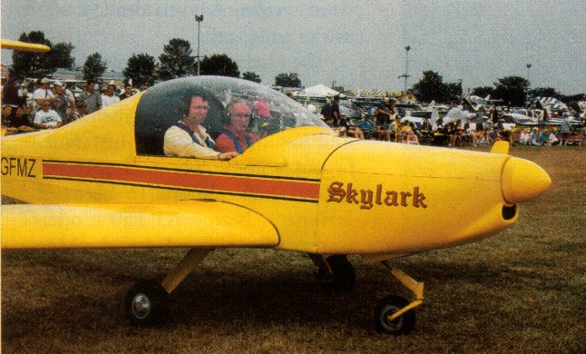
Design of the all metal, T tail, side by side two place Skylark began in January 1999, with the first flight on 10 March 2000. After the first flight, all that was required was a change to the incidence on the horizontal tail.
The Skylark is basically a 6061-T6 aluminium structure aircraft with 0.016 2024-T3 Alclad in the control surfaces. Winglets, engine cowling, tips and main landing gear legs are composite. The wing is tapered with the same wing section across the entire span. A channel type spar, located at 38% chord, is 9 in high and reinforced at the root. It tapers to 7 in at the tip. Each wing panel is fitted with six ribs stamped from 0.025 in 6061 sheet and has three full span skins. Wings are bolted to the fuselage carry-through spar.
Seven foot span, 7.25 in flaperons actuate the flap function mechanically by a handle below the centered throttle quadrant. They reflex (move up) 10 degrees for cruise.
The wing employs an IARV 419 airfoil that was designed by Stephen Marsden. It is a high lift, laminar flow profile specifically designed not to be sensitve to surface roughness due to ice, rain, and snow.
The fuselage is a semi-monocoque structure with three formers aft of the cockpit, which is 43 in wide and has dual controls. A 4.25 cu.ft baggage area is behind the seats. The stabiliser and elevator have a 9 ft span each. A 48 in electrically operated trim tab is installed on the left side of the elevator. The fin is reinforced at the root. Rudder height is 50 in. All of the tail control surfaces are D-cell structures with ribs but no spars. The elevator has six ribs, and the rudder has three.
Main gear legs carry Cleveland wheels and brakes, with 5.00×5 McClreary tires. The nosegear castors, employing a 4130 square steel leg with a spring shock absorber and a 5.00×4 Lamb tire. Main gear tread is 79 in, and wheelbase is 48 in.
Two 14.5 USG welded aluminium fuel tanks are located behind the wing spar, starting at the root and extending 35 in.
Skylark has double tip winglets. As part of the development program, a single winglet was added after the first flight, positioned at the front of the tip. It did assist tip airflow and split the vortices in two parts. Marsden deduced that dual winglets would work better. He added a second winglet, canted out at 45 degrees, that splits the vortices into three parts. This increased effectiveness about 50% over the single winglet.
For takeoff, flaps are set 10 degrees down. On approach, 20 degrees flap are set for landing for better visiblity. The aileron differential is 10 degrees up and 15 degrees down from whatever the flap angle is set. Downwind approach is at 80 mph, reducing to 70 on base and final, with a touchdown speed of 54 mph.
Engine: Rotax 912, 80 hp Prop: CSC wood, ground adjustable 68 in hp range: 85-150 Wingspan: 22 ft Wing chord: 48 in Wing area; 92 sq.ft Empty weight; 655 lb MAUW: 1200 lb Fuel capacity: 2 x 14.5 USG Max level speed; 130 mph Stall 20 deg flap: 50 mph Cruise 75%: 120 mph Fuel burn at 75%: 4 USGph Econ cruise: 90 mph Fuel burn at econ cruise: 2.5 USGph Stress: +6 / -4 Takeoff run; 500 ft Takeoff speed: 52 mph Climb rate: 650 fpm at 75-80 mph Vne: 210 mph Range at 120 mph: 700 mile Landing distance: 500 ft