As an aeronautical engineer who had collaborated in programmes from such as Apollo X 15 and XB 70, Chuck Slusarczyk founded CGS (Chuck’s Glider Supplies) in 1972 and around 2000 hang gliders were sold in five years. This company was made famous by the creation and distribution of the first drive unit specifically designed for microlights, the famous Power Hawk.
In the early 1970’s, Chuck Slusarczyk designed, built, and sold hang gliders and various associated supplies. Shortly thereafter, he began experimenting with the powered hang glider, propelled at the time by small direct-drive go-kart engines. The propeller was bolted directly to the crankshaft of the engine and turned at high (5,000-6,000 rpm) speeds. Chuck realized that this design was not efficient.
With this shortcoming as impetus, Chuck successfully designed and produced a power system implementing a reduction drive to turn a larger-diameter, more efficient propeller. By 1977, Chuck’s Glider Supplies had become a leading manufacturer of hang gliders with a successful division producing power plants for a variety of ultralights. For his pioneering efforts, Chuck was awarded Patent No. 4.262.263, “Powered Hang Glider with Reduction Drive.” Slusarczyk declined to take legal action against his competition for patent infringement.
In October, 1979, Chuck’s Glider Supplies became CGS Aviation, Inc. In early 1980, CGS conducted a market study at Sun N Fun and also Oshkosh to determine the features of an ultralight most desired by pilots. The “Hawk” was the end result of that study. The first prototype took to the air in January 1982.
1982: CGS Aviation Inc, 1305 Lloyd Road, Wickliffe, Ohio 44092, USA.
1995-8: PO Box 470635, Broadview Heights, OH 44147, USA.
2009: CGS Aviation
9090 Louis Tillman Rd
Grand Bay, AL 36541-5210
CGS Aviaton came under new ownership. Due to health issues, Chuck Slusarczyk, the founder of CGS, passed on the Hawk design and daily manufacturing operations of the company. New owner and president, Danny Dezauche, Tony Warnock serve as Operations Officer and Steve Bensinger the Technical Director. Chuck continued to provide technical assistance as needed.
2000->
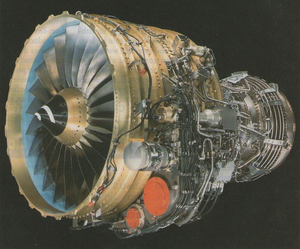
CFM International CFM56 / F108
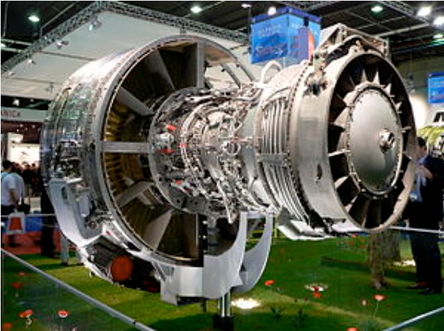
Research into the high-bypass ratio turbofans in the “10-ton” (20,000 lbf; 89 kN) thrust class, began in the late 1960s. SNECMA, who had mostly built military engines until then, was the first company to seek entrance into the market by searching for a partner with commercial experience to design and build an engine in this class. They considered Pratt & Whitney, Rolls-Royce, and GE Aviation as potential partners, but it was not until after two company executives, Gerhard Neumann from GE and René Ravaud from SNECMA, introduced themselves at the 1971 Paris Air Show that a decision was made. The two companies saw mutual benefit in the collaboration and met several more times, fleshing out the basics of the joint project.
Pratt & Whitney dominated the commercial market at this point in time. GE needed an engine in this market class, and SNECMA had previous experience of working with them, collaborating on the production of the CF6-50 turbofan for the Airbus A300. Pratt & Whitney was considering upgrading their JT8D to compete in the same class as the CFM56 as a sole venture, while Rolls-Royce dealt with financial issues that precluded them from starting new projects; this situation caused GE to gain the title of best partner for the program.
A major reason for GE’s interest in the collaboration, rather than building a 10-ton engine on their own, was that the SNECMA project was the only source of development funds for an engine in this class at this particular time. GE was initially considering only contributing technology from its CF6 engine rather than its much more advanced F101 engine, developed for the B-1 Lancer supersonic bomber. However, the company was faced with a dilemma when the United States Air Force (USAF) announced its Advanced Medium STOL Transport (AMST) project in 1972 which included funding for the development of a 10-ton engine – either to build a “limited” technology 10-ton engine with SNECMA, or a similar engine with “advanced” technology on their own. Concerned that the company would be left with only the “limited” engine in its portfolio if it did not win the Air Force contract (for which it was competing with Pratt & Whitney and a General Motors division with its “advanced” engine), GE decided to apply for an export license for the F101 core technology.
GE applied for the export license in 1972 as their primary contribution to the 10-ton engine project. However, the United States Department of State’s Office of Munitions Control recommended the rejection of the application on national security grounds; specifically because the core technology was an aspect of a strategic national defense system (the B-1 bomber), it was built with Department of Defense (and therefore American taxpayer) money, and that exporting the technology to France would limit the number of American workers on the project. The official decision was made in a National Security Decision Memorandum signed by the National Security Advisor Henry Kissinger on 19 September 1972.
While national security concerns were cited as the grounds for rejection, reportedly high-level politics played an important role as well. The project, and the export issue associated with it, was considered so important that French President Georges Pompidou appealed directly to U.S. President Richard Nixon in 1971 to approve the deal, and that Henry Kissinger brought the issue up with President Pompidou in a 1972 meeting. GE reportedly argued at the highest levels that having half of the market was better than having none of it, which they believed would happen if SNECMA pursued the engine on their own without GE’s contribution. However, Nixon administration officials feared that this project could be the beginning of the end of American aerospace leadership.
There was also speculation that the rejection may have been, in part, retaliation for French involvement in convincing the Swiss not to purchase American-made A-7 Corsair II aircraft that had been competing against a French design, the Dassault Milan. In the end, the Swiss did not purchase either aircraft, opting for the Northrop F-5E Tiger II instead.
Despite the export license being rejected, both the French and GE continued to push the Nixon Administration for permission to export the F101 technology. Efforts continued throughout the months following the rejection, culminating in the engine becoming an agenda topic during the 1973 meeting of Presidents Nixon and Pompidou in Reykjavík. Discussions at this meeting resulted in an agreement that allowed the development of the CFM56 to proceed. Contemporary reports state that the agreement was based on assurances that the core of the engine, the part that GE was developing from the military F101, would be built in the U.S. and then transported to France in order to protect the sensitive technologies. The joint venture also agreed to pay the U.S. an $80 million royalty fee (calculated at $20,000 per engine predicted to be built) as repayment for the development money provided by the government for the F101 engine core. Documents declassified in 2007 revealed that a key aspect of the CFM56 export agreement was that the French government agreed not to seek tariffs against American aircraft being imported into Europe.
With the export issue settled, GE and SNECMA finalized the agreement that formed CFM International (CFMI), a 50–50 joint company that would be responsible for producing and marketing the 10-ton engine, the CFM56. The venture was officially founded in 1974. The two primary roles for CFMI were to manage the program between GE and SNECMA, and to market, sell and service the engine at a single point of contact for the customer. CFMI was made responsible for the day-to-day decision making for the project, while major decisions (developing a new variant, for example) required the go-ahead from GE and SNECMA management.
The CFMI board of directors is currently split evenly between SNECMA and GE (five members each). There are two vice presidents, one from each company, who support the President of CFMI. The president tends to be drawn from SNECMA and sits at CFMI’s headquarters near GE in Cincinnati, Ohio.
The work split between the two companies gave GE responsibility for the high-pressure compressor (HPC), the combustor, and the high-pressure turbine (HPT); while SNECMA was responsible for the fan, the low-pressure compressor (LPC), and the low-pressure turbine (LPT). SNECMA was also responsible for the initial airframe integration engineering, mostly involving the nacelle design, and was initially responsible for the gearbox, but shifted that work to GE when it became apparent that it would be more efficient for GE to assemble that component along with their other parts.
Development work on the CFM56 began before CFMI was formally created. While work proceeded smoothly, the international arrangement led to unique working conditions. For example, both companies had assembly lines, some engines were assembled and tested in the U.S. and others in France. Engines assembled in France were subject to the initially strict export agreement, which meant that GE’s core was built in the U.S., then shipped to the SNECMA plant in France where it was placed in a locked room into which even the President of SNECMA was not allowed. The SNECMA components (the fore and aft sections of the engine) were brought into the room, GE employees mounted them to the core, and then the assembled engine was taken out to be finished.
The first completed CFM56 engine first ran at GE in June 1974 with the second running in October 1974. The second engine was then shipped to France and first ran there on 13 December 1974. These first engines were considered “production hardware” as opposed to test examples and were designated as the CFM56-2, the first variant of the CFM56.
The engine flew for the first time in February 1977 when it replaced one of the four Pratt & Whitney JT8D engines on the McDonnell Douglas YC-15, an entrant in the Air Force’s Advanced Medium STOL Transport (AMST) competition. Soon after, the second CFM56 was mounted on a Sud Aviation Caravelle at the SNECMA flight test center in France. This engine had a slightly different configuration with a long bypass duct and mixed exhaust flow, rather than a short bypass duct with unmixed exhaust flow. It was the first to include a “Thrust Management System” to maintain engine trim.
After testing the engine for several years, both in the air and on the ground, CFMI searched for customers outside of a possible AMST contract. The main targets were re-engine contracts for the Douglas DC-8 and the Boeing 707 airliners, including the related military tanker, the KC-135 Stratotanker. There was little initial interest in the engine, but Boeing realized that the CFM56 might be a solution to upcoming noise regulations. After announcing that a 707 would be configured with the CFM56 engine for flight tests in 1977, Boeing officially offered the 707-320 with the CFM56 engine as an option in 1978. The new variant was listed as the 707-700. However, due to limited interest from the airlines in a re-engined 707, Boeing ended the 707-700 program in 1980 without selling any aircraft. Despite the lack of sales, having the commercial 707 available with the CFM56 helped the engine’s competitiveness for the KC-135 re-engine contract.
Winning the contract to re-engine the KC-135 tanker fleet for the USAF would be a huge boon to the CFM56 project (with more than 600 aircraft available to re-engine), and CFMI aggressively pursued that goal as soon as the Request For Proposals (RFP) was announced in 1977. Like other aspects of the program, international politics played their part in this contract. In efforts to boost the CFM56’s chances versus its competitors, the Pratt & Whitney TF33 and an updated Pratt & Whitney JT8D, the French government announced in 1978 that they would upgrade their 11 KC-135s with the CFM56, providing one of the first orders for the engine.
The USAF announced the CFM56 as the winner of the re-engine contract in January 1980. Officials indicated that they were excited at the prospect of replacing the Pratt & Whitney J57 engines currently flying on the KC-135A aircraft, calling them “…the noisiest, dirtiest, [and] most fuel inefficient powerplant still flying” at the time. The re-engined aircraft was designated the KC-135R. The CFM56 brought many benefits to the KC-135, decreasing takeoff distance by as much as 3,500 ft (1,100 m), decreasing overall fuel usage by 25%, greatly reducing noise (24 dB lower) and lowering total life cycle cost. With those benefits in mind, the United States Navy selected the CFM56-2 to power their variant of the Boeing 707, the E-6 Mercury, in 1982. Additionally, in 1984 the Royal Saudi Air Force selected the CFM56-2 to power their E-3 Sentry aircraft (also related to the 707 airframe). The CFM56-2-powered E-3 also became the standard configuration for aircraft purchased by the British and French.
By the end of the 1970s, airlines were considering upgrading their aging Douglas DC-8 aircraft as an alternative to buying new quieter and more efficient aircraft. Following the French KC-135 order in 1978, the April 1979 decision by United Airlines to upgrade 30 of their DC-8-61 aircraft with the CFM56-2 was important for securing the development of the CFM56; GE and SNECMA were two weeks away from freezing development had that order not materialized. This decision marked the first commercial purchase (rather than government/military) of the engine, and Delta Air Lines and Flying Tiger Line soon followed suit, giving the CFM56 a firm footing in both the military and commercial realms.
In the early 1980s Boeing selected the CFM56-3 to exclusively power the latest Boeing 737 variant, the 737-300. The 737 wings were closer to the ground than previous applications for the CFM56, necessitating several modifications to the engine. The fan diameter was reduced, which reduced the bypass ratio, and the engine accessory gearbox was moved from the bottom of the engine (the 6 o’clock position) to the 9 o’clock position, giving the engine nacelle its distinctive flat-bottomed shape. The overall thrust was also reduced, from 24,000 to 20,000 lbf (110 to 89 kN), mostly due to the reduction in bypass ratio.
Since the small initial launch order for twenty 737-300s split between two airlines, over 5,000 Boeing 737 aircraft had been delivered with CFM56 turbofans by April 2010, resounding proof of the engine’s adaptability.
Once the CFM56 was well established in both military and commercial applications, CFMI continued to improve the engine and market it for new aircraft, such as the Airbus A320 and the Airbus A340. As of 2010, there are four major variants of the engine, each with multiple sub-variants.
In 1998, CFMI launched the “Tech56” development and demonstration program to create an engine for the new single-aisle aircraft that were expected to be built by Airbus and Boeing. The program focused on developing a large number of new technologies for the theoretical future engine, not necessarily creating an all-new design. However, when it became clear that Boeing and Airbus were not going to build all-new aircraft to replace the 737 and A320, CFMI decided to apply some of those Tech56 technologies to the CFM56 in the form of the “Tech Insertion” program which focused on three areas: fuel efficiency, maintenance costs and emissions. Launched in 2004, the package included redesigned high-pressure compressor blades, an improved combustor, and improved high- and low-pressure turbine components which resulted in better fuel efficiency and lower nitrogen oxides (NOx) emissions. The new components also reduced engine wear, lowering maintenance costs by about 5%. The engines entered service in 2007, and all new CFM56-5B and CFM56-7B engines were being built with the Tech Insertion components. CFMI also offers the components as an upgrade kit for existing engines.
By 2000, General Electric hds established a moving line, similar in concept to the classic automobile assembly line, to reduce the time it takes to manufacture CFM International powerplants.
The line focused on cutting CFM engine manufacturing time to seven days, from 11, by about June 2000, Ken Foley, CFM56-5 project general manager, said. CFM56 engine production has grown from 380 engines delivered in 1995 to about 1,080 in 1999, and about 1,050 engines scheduled for delivery in 2000.
GE and Snecma said that none of their CFM56 engines have been delivered late since production started skyrocketing. CFM production at GE is centered on producing core engines for the entire CFM stable, as well as delivering completed CFM56-7 powerplants. Snecma production is grouped around producing fans for all CFM products, as well as assembling complete CFM56-family engines.
According to Snecina executives, the 35 -hr. workweek, which was implemented in France on Feb. 1 2000, was not expected to increase the companys production costs. Additional productivity gains, sustained by the CFM56’s production rate, should counterbalance the shortened workweek, they added.
1999 was the joint companys fourth best year ever for sales. More than 1,000 CFM engines worth about $5 billion were ordered, and a new application was found for the CFM56-513, the Airbus A318.
Dispatch reliability for CFM56s was running above 99.9%, and inflight shutdown rates were low – about 0.001 incidents per 1,000 engine flight hours for the -5B powerplant and about 0.006 for the -7 version. The company has seen five CFM56-3 and three CFM56-5C engines remain on wing for above 30,000 flight hours. For the -3 powerplant, that translates to about eight years of service before removal.
CFMI signed an agreement with llyushin to explore reengining Il-76 transports with CFM56-5C4 engines. The program would be launched if orders for five reengined aircraft were concluded.
CFM56 components are already manufactured in China (2000).
In 2009, CFMI announced the latest upgrade to the CFM56 engine, the “CFM56-7B Evolution” or CFM56-7BE. This upgrade, announced alongside Boeing’s newest 737 variant, further enhances the high- and low-pressure turbines with better aerodynamics, as well as improving engine cooling, and aims to reduce overall part count. CFMI expected the changes to result in a 4% reduction in maintenance costs and a 1% improvement in fuel consumption (2% improvement including the airframe changes for the new 737); however, flight and ground tests completed in May 2010 revealed that the fuel burn improvement was better than expected at 1.6%. Following 450 hours of testing, the CFM56-7BE engine was certified by FAA and EASA on 30 July 2010.
While the CFM56-7BE engine is designed specifically for Boeing’s new 737, CFMI have proposed a similar Evolution upgrade for the CFM56-5B engines that power Airbus’s A320. As of May 2010, Airbus has not made any commitment to a new engine.
The CFM56 is a high-bypass turbofan engine with several variants having bypass ratios ranging from 5:1 to 6:1, generating 18,500 to 34,000 lbf (80 kN to 150 kN) of thrust. The variants share a common design, but the details differ. The CFM56 is a two-shaft (or two-spool) engine, meaning that there are two rotating shafts, one high-pressure and one low-pressure. Each is powered by its own turbine section (the high-pressure and low-pressure turbines, respectively). The fan and booster (low pressure compressor) evolved over the different iterations of the engine, as did the compressor, combustor and turbine sections.
Most variants of the CFM56 feature a single-annular combustor. An annular combustor is a continuous ring where fuel is injected into the airflow and ignited, raising the pressure and temperature of the flow. Other types of combustors include can combustors, where each combustion chamber is separate, and canannular which is a hybrid of the two.
In 1989, CFMI began work on a new, double-annular combustor. Instead of having just one combustion zone, the double-annular combustor has a second combustion zone that is used at high thrust levels. This design lowers the emissions of both nitrogen oxides (NOx) and carbon dioxide (CO2). The first CFM56 engine with the double-annular combustor entered service in 1995, and the combustor is used on “Tech Insertion” CFM56-5B and CFM56-7B variants.
GE started developing and testing a new type of combustor called the Twin Annular Premixing Swirler combustor, or “TAPS”, during the Tech 56 program. This design is similar to the double-annular combustor in that it has two combustion zones; however, this combustor “swirls” the flow, creating an ideal fuel–air mixture. This difference allows the combustor to generate much less NOx than other combustors. Tests on a CFM56-7B engine demonstrated an improvement of 46% over single-annular combustors and 22% over double-annular combustors. The analytical tools developed for TAPS have also been used to improve other combustors, notably the single-annular combustors in some CFM56-5B and -7B engines.
The high-pressure compressor-HPC, is at the center of the original export controversy features 9stages in each variants of the CFM56. The compressor stages has been developed from GE`s “GE1/9 core” (namely a single-turbine, nine-compressor stage design) which was designed in a compact core rotor. The small span of the compressor radius meant that the entire engine could be lighter and smaller,as the accessory units in the system (bearings,oiling systems) could be merged to the main fueling system running on aviation fuel. As design evolved HPC design improved through better airfoil design. As part of the Tech-56 improvement program CFMI has tested the new CFM-56 model with six-stage high-pressure compressor stages (discs that make up the compressor system) that was designed to deliver same pressure ratios (pressure gain 30) similar to the old nine-stages compressor design. While the new one was not fully replacing the old one, it offered an upgrade in HPC, thanks to improved blade dynamics, as a part of their “Tech Insertion” management plan from 2007.
Although CFMI tested both a mixed and unmixed exhaust design at the beginning of development, most variants of the engine feature an unmixed exhaust nozzle. Only the high-power CFM56-5C, designed for the Airbus A340, has a mixed-flow exhaust nozzle.
Additionally, GE and SNECMA tested the effectiveness of chevrons on reducing jet noise. After examining configurations in the wind tunnel, CFMI chose to flight-test chevrons built into the core exhaust nozzle. The chevrons reduced jet noise by 1.3 perceived loudness decibels during takeoff conditions, and were offered as an option with the CFM56 for the Airbus A321.
The CFM56 became one of the most common turbofan aircraft engines in the world, with more 22,208 having been built in four major variants by June 2011. It is the only engine (CFM56-5C) used to power the Airbus A340-200 and 300 series. The engine (CFM56-5A and 5B) is also fitted to Airbus A320 series aircraft.
The CFM56 features a single-stage fan, and most variants have a three-stage booster on the low-pressure shaft, with four stages in the -5B and -5C variants. The booster is also commonly called the “low-pressure compressor” (LPC) as it sits on the low-pressure shaft and compresses the flow initially before reaching the high-pressure compressor. The original CFM56-2 variant featured 44 tip-shrouded fan blades, although the number of fan blades was reduced in later variants as wide-chord blade technology developed, down to 22 blades in the latest variant, the CFM56-7.
The CFM56 fan features dovetailed fan blades which allows them to be replaced without removing the entire engine, and GE/SNECMA claim that the CFM56 was the first engine to have that capability. This attachment method is useful for circumstances where only a few fan blades need to be repaired or replaced, such as following bird strikes.
The fan diameter varies with the different models of the CFM56, and that change has a direct impact on the engine performance. For example, the low-pressure shaft rotates at the same speed for both the CFM56-2 and the CFM56-3 models; however, the fan diameter is smaller on the -3, which lowers the tip speed of the fan blades. The lower speed allows the fan blades to operate more efficiently (5.5% more in this case), which increases the overall fuel efficiency of the engine (improving specific fuel consumption nearly 3%).
The CFM56 is designed to support several reverse thrust systems. The variants built for the Boeing 737, the CFM56-3 and the CFM56-7, use a cascade type of thrust reverser. This type of thrust reverse consists of sleeves that slide back to expose mesh-like cascades and blocker doors that block the bypass air flow. The blocked bypass air is forced through the cascades, reducing the thrust of the engine and slowing the aircraft down.
The CFM56 also supports pivoting-door type thrust reversers. This type is used on the CFM56-5 engines that power many Airbus aircraft. They work by actuating a door that pivots down into the bypass duct, both blocking the bypass air and deflecting the flow outward, creating the reverse thrust.
All variants of the CFM56 feature a single-stage high-pressure turbine (HPT). In some variants, the HPT blades are “grown” from a single crystal superalloy, giving them high strength and creep resistance. The low-pressure turbine (LPT) features four stages in most variants of the engine, but the CFM56-5C has a five-stage LPT. This change was implemented to drive the larger fan on this variant. Improvements to the turbine section were examined during the Tech56 program, and one development was an aerodynamically optimized low-pressure turbine blade design, which would have used 20% fewer blades for the whole low-pressure turbine, saving weight. Some of those Tech56 improvements made their way into the Tech Insertion package, where the turbine section was updated. The turbine section was updated again in the “Evolution” upgrade.
The high-pressure turbine stages in the CFM56 are internally cooled by air from the high-pressure compressor. The air passes through internal channels in each blade and ejects at the leading and trailing edges.
Several fan blade failure incidents were experienced during the CFM56’s early service, including one failure that was noted as a cause of the Kegworth air disaster, while some variants of the engine experienced problems caused by flight through rain and hail. However, both these issues were resolved with engine modifications.
Although the CFM56 is a very reliable engine (CFMI state that there is only one in-flight shutdown every 333,333 hours), there have been several engine failures throughout the life of the CFM56 family which were serious enough to either ground the fleet or require aspects of the engine to be redesigned.
There are several recorded incidents of CFM56 engines flaming out in heavy rain and/or hail conditions, beginning early in the CFM56’s career. In 1987, a double flameout occurred in hail conditions (the pilots managed to relight the engines), followed by the TACA Flight 110 incident in 1988. Both CFM56 engines on the TACA 737 flamed out while passing through hail and heavy rain, and the crew was forced to land without engines on a grassy levee near New Orleans, Louisiana. CFMI modified the engines by adding a sensor to force the combustor to continuously ignite under those conditions.
In 2002, Garuda Indonesia Flight 421 had to ditch into a river because of hail-induced engine flameouts, killing a flight attendant and injuring dozens of passengers. Prior to this accident, there were several other incidents of single or dual flameouts due to these weather conditions. After three incidents through 1998, CFMI made modifications to the engine to improve the way in which the engine handled hail ingestion. The major changes included a modification to the fan/booster splitter (making it more difficult for hail to be ingested by the core of the engine) and the use of an elliptical, rather than conical, spinner at the intake. While these changes did not prevent the 2002 accident, the investigation board found that the pilots did not follow the proper procedures for attempting to restart the engine, which contributed to the final result. Recommendations were made to better educate pilots on how to handle these conditions, as well as to revisit FAA rain and hail testing procedures. No further engine modifications were recommended.
One issue that led to accidents with the CFM56-3C engine was the failure of fan blades. This mode of failure led to the Kegworth air disaster in 1989, which killed 47 people and injured 74 more. After the fan blade failed, the pilots mistakenly shut down the wrong engine, resulting in the damaged engine failing completely when powered up after descent. Following the Kegworth accident, CFM56 engines fitted to a Dan-Air 737-400 and a British Midland 737-400 suffered fan blade failures under similar conditions, although neither incident resulted in a crash or injuries. After the second incident, the 737-400 fleet was grounded.
At the time it was not mandatory to flight test new variants of existing engines, and certification testing failed to reveal vibration modes that the fan experienced during the regularly performed power climbs at high altitude. Analysis revealed that the fan was being subjected to worse than expected high-cycle fatigue stresses, causing the blade to fracture; and more severe than tested for certification. Less than a month after grounding, the fleet was allowed to resume operations once the fan blades and fan disc were replaced and the electronic engine controls were modified to reduce maximum engine thrust to 22,000 lbf (98 kN) from 23,500 lbf (105 kN). The redesigned fan blades were installed on all CFM56-3C1 and CFM56-3B2 engines, including over 1,800 engines that had already been delivered to customers.
By January 2010, the CFM56 had flown more than 470 million cumulative hours (the equivalent of more than 53,000 years).
Variants:
CFM56-2 series / F108
The CFM56-2 series is the original variant of the CFM56. It is most widely used in military applications where it is known as the F108; specifically in the KC-135, the E-6 Mercury and some E-3 Sentry aircraft. The CFM56-2 comprises a single-stage fan with 44 blades, with a three-stage LP compressor driven by a four-stage LP turbine, and a nine-stage HP compressor driven by a single-stage HP turbine. The combustor is annular.
Applications
CFM56-2A-2 (-3)
E-3 Sentry, E-6 Mercury
CFM56-2B1
KC-135R Stratotanker, Boeing RC-135
CFM56-2C1
Douglas DC-8-70
CFM56-3 series
The first derivative of the CFM56 series, the CFM56-3 is designed for Boeing 737-300/-400/-500 series aircraft, with static thrust ratings from 18,500 to 23,500 lbf (82.3 to 105 kN). A “cropped fan” derivative of the -2, the -3 engine has a smaller fan diameter at 60 in (1.5 m) but retains the original basic engine layout. The new fan is primarily derived from GE’s CF6-80 turbofan rather than the CFM56-2, and the booster was redesigned to match the new fan.
A significant challenge for this series was achieving ground clearance for the wing-mounted engine. This was overcome by reducing the intake fan diameter and relocating the gearbox and other accessories from beneath the engine to the sides. The resulting flattened nacelle bottom and intake lip yielded the distinctive appearance of the Boeing 737 with CFM56 engines.
Applications:
CFM56-3B-1
Boeing 737-300, Boeing 737-500
CFM56-3B-2
Boeing 737-300, Boeing 737-400
CFM56-3C-1
Boeing 737-300, Boeing 737-400, Boeing 737-500
CFM56-4 series
The CFM56-4 series was a proposed improved version of the CFM56-2 designed for the Airbus A320 family of aircraft. Competing with the RJ500 engine being developed by Rolls-Royce, the -4 series was designed to produce 25,000 lbf (110 kN) and was to feature a new 68 in (1.73 m) fan, a new low-pressure compressor and a Full Authority Digital Engine Controller (FADEC). However, soon after the upgrade project was launched in 1984, International Aero Engines offered their new V2500 engine for the A320. CFMI realized that the CFM56-4 did not compare favorably with the new engine and scrapped the project to begin working on the CFM56-5 series.
CFM56-5 series
CFM56-5 at Airbus A320-200The CFM56-5 series is designed for the Airbus aircraft and has a very wide thrust rating of between 22,000 and 34,000 lbf (97.9 and 151 kN). It has three distinct sub-variants; the CFM56-5A, CFM56-5B and CFM56-5C, and differs from its Boeing-fitted cousins by featuring a FADEC and incorporating further aerodynamic design improvements.
CFM56-5A series
The CFM56-5A series is the initial CFM56-5 series, designed to power the short-to-medium range Airbus A320 family. Derived from the CFM56-2 and CFM56-3 families, the -5A series produces thrusts between 22,000 and 26,500 lbf (98 kN and 118 kN). Aerodynamic improvements such as an updated fan, low-pressure compressor, high-pressure compressor and combustor make this variant 10–11% more fuel efficient than its predecessors.
Applications:
CFM56-5A1
Airbus A320
CFM56-5A3
Airbus A320
CFM56-5A4
Airbus A319
CFM56-5A5
Airbus A319
CFM56-5B series
An improvement of the CFM56-5A series, it was originally designed to power the A321. With a thrust range between 22,000 and 33,000 lbf (98 kN and 147 kN) it can power every model in the A320 family (A318/A319/A320/A321) and has superseded the CFM56-5A series. Among the changes from the CFM56-5A is the option of a double-annular combustor that reduces emissions (particularly NOx), a new fan in a longer fan case, and a new low-pressure compressor with a fourth stage (up from three in earlier variants). It is the most numerous engine supplied to Airbus.
Applications:
CFM56-5B1
Airbus A321
CFM56-5B2
Airbus A321
CFM56-5B3
Airbus A321
CFM56-5B4
Airbus A320
CFM56-5B5
Airbus A319
CFM56-5B6
Airbus A319
CFM56-5B7
Airbus A319, A319CJ
CFM56-5B8
Airbus A318
CFM56-5B9
Airbus A318
CFM56-5C series
With a thrust rating of between 31,200 and 34,000 lbf (139 kN and 151 kN), the CFM56-5C series is the most powerful of the CFM56 family. It powers Airbus’ long-range A340-200 and -300 airliners, and entered service in 1993. The major changes are a larger fan, a fifth low-pressure turbine stage, and the same four-stage low-pressure compressor found in the -5B variant.
Unlike every other variant of the CFM56, the -5C features a mixed-exhaust nozzle, which offers slightly higher efficiency.
Applications:
CFM56-5C2
Airbus A340-200/-300
CFM56-5C3
Airbus A340-200/-300
CFM56-5C4
Airbus A340-200/-300
CFM56-7 series
The CFM56-7 powers the Boeing 737 Next Generation series (737-600/-700/-800/-900). The CFM56-7 is rated with takeoff thrust from 19,500 to 27,300 lbf (86.7 kN to 121 kN). It has higher thrust ranges, improved efficiency, and lower maintenance costs than its predecessor, the CFM56-3 series. It incorporates features from the CFM56-5 series such as FADEC, double-annular combustor (as an option), and improved internal design. The basic mechanical arrangement is as the -3 series, but all aspects were aerodynamically improved from that model. For example, the improved wide-chord fan blades allowed the total number of fan blades to be reduced from 38 to 24. Other improvements came from material advances, such as the use of single-crystal turbine blades in the high-pressure turbine.
The CFM56-7-powered 737 was granted 180-minute Extended-Range, Twin-Engine Operations (ETOPS) approval by the U.S. Federal Aviation Administration. It also powers the military versions of the Next-Generation 737, the C-40 Clipper, the P-8 Poseidon, and Boeing 737 AEW&C.
Applications:
CFM56-7B18
Boeing 737-600
CFM56-7B20
Boeing 737-600, Boeing 737-700
CFM56-7B22
Boeing 737-600, Boeing 737-700
CFM56-7B24
Boeing 737-700, Boeing 737-800, Boeing 737-900
CFM56-7B26
Boeing 737-700, Boeing 737-800, Boeing 737-900
CFM56-7B27
Boeing 737-800, Boeing 737-900, Boeing Business Jet
Specifications:
CFM56-2A-2 (-3)
Thrust: 24,000 lbf (110 kN)
Bypass Ratio: 5.9
Pressure Ratio: 31.8
Dry Weight: 4,820 lb / 2,190 kg
CFM56-2B1
Thrust: 22,000 lbf (98 kN)
Bypass Ratio: 6.0
Pressure Ratio: 30.5
Dry Weight: 4,671 lb / 2,120 kg
CFM56-2C1
Thrust: 22,000 lbf (98 kN)
Bypass Ratio: 6.0
Pressure Ratio: 31.3
Dry Weight: 4,653 lb / 2,110 kg
CFM56-3B-1
Thrust: 20,000 lbf (89 kN)
Bypass Ratio: 6.0
Pressure Ratio: 27.5
Dry Weight: 4,276 lb / 1,940 kg
CFM56-3B-2
Thrust: 22,000 lbf (98 kN)
Bypass Ratio: 5.9
Pressure Ratio: 28.8
Dry Weight: 4,301 lb / 1,950 kg
CFM56-3C-1
Thrust: 23,500 lbf (100 kN)
Bypass Ratio: 6.0
Pressure Ratio: 30.6
Dry Weight: 4,301 lb / 1,950 kg
CFM56-5A1
Thrust: 25,000 lbf (111 kN)
Bypass Ratio: 6.0
Pressure Ratio: 31.3
Dry Weight: 4,995 lb / 2,270 kg
CFM56-5A3
Thrust: 26,500 lbf (118 kN)
Bypass Ratio: 6.0
Pressure Ratio: 31.3
Dry Weight: 4,995 lb (2,270 kg)
CFM56-5A4
Thrust: 22,000 lbf (97.9 kN)
Bypass Ratio: 6.2
Pressure Ratio: 31.3
Dry Weight: 4,995 lb (2,270 kg)
CFM56-5A5
Thrust: 23,500 lbf (105 kN)
Bypass Ratio: 6.2
Pressure Ratio: 31.3
Dry Weight: 4,995 lb (2,270 kg)
CFM56-5B1
Thrust: 30,000 lbf (130 kN)
Bypass Ratio: 5.5
Pressure Ratio: 35.4
Dry Weight: 5,250 lb (2,380 kg)
CFM56-5B2
Thrust: 31,000 lbf (140 kN)
Bypass Ratio: 5.5
Pressure Ratio: 35.4
Dry Weight: 5,250 lb (2,380 kg)
CFM56-5B3
Thrust: 33,000 lbf (150 kN)
Bypass Ratio: 5.4
Pressure Ratio: 35.5
Dry Weight: 5,250 lb (2,380 kg)
CFM56-5B4
Thrust: 27,000 lbf (120 kN)
Bypass Ratio: 5.7
Pressure Ratio: 32.6
Dry Weight: 5,250 lb (2,380 kg)
CFM56-5B5
Thrust: 22,000 lbf (98 kN)
Bypass Ratio: 6.0
Pressure Ratio: 32.6
Dry Weight: 5,250 lb (2,380 kg)
CFM56-5B6
Thrust: 23,500 lbf (100 kN)
Bypass Ratio: 5.9
Pressure Ratio: 32.6
Dry Weight: 5,250 lb (2,380 kg)
CFM56-5B7
Thrust: 27,000 lbf (120 kN)
Bypass Ratio: 5.7
Pressure Ratio: 35.5
Dry Weight: 5,250 lb (2,380 kg)
CFM56-5B8
Thrust: 21,600 lbf (96 kN)
Bypass Ratio: 6.0
Pressure Ratio: 32.6
Dry Weight: 5,250 lb (2,380 kg)
CFM56-5B9
Thrust: 23,300 lbf (100 kN)
Bypass Ratio: 5.9
Pressure Ratio: 32.6
Dry Weight: 5,250 lb (2,380 kg)
CFM56-5C2
Thrust: 31,200 lbf (139 kN)
Bypass Ratio: 6.6
Pressure Ratio: 37.4
Dry Weight: 8,796 lb (3,990 kg)
CFM56-5C3
Thrust: 32,500 lbf (145 kN)
Bypass Ratio: 6.5
Pressure Ratio: 37.4
Dry Weight: 8,796 lb (3,990 kg)
CFM56-5C4
Thrust: 34,000 lbf (151 kN)
Bypass Ratio: 6.4
Pressure Ratio: 38.3
Dry Weight: 8,796 lb (3,990 kg)
CFM56-7B18
Type: Twin-spool, high-bypass turbofan
Length: 98.7 in (2.5 m)
Diameter: 61 in (1.55 m) (fan)
Dry weight: 5,216 lb (2,366 kg) (dry)
ComponentsCompressor: Single-stage fan, 3-stage low-pressure compressor, 9-stage high-pressure compressor
Combustors: annular
Turbine: Single-stage high-pressure turbine, 4-stage low-pressure turbine
Maximum thrust: 19,500 lbf (86.7 kN)
Overall pressure ratio: 32.8:1
Bypass ratio: 5.5:1
Thrust-to-weight ratio: 3.7:1
CFM56-7B20
Thrust: 20,600 lbf (91.6 kN)
Bypass Ratio: 5.5
Pressure Ratio: 32.8
Dry Weight: 5,216 lb (2,370 kg)
CFM56-7B22
Thrust: 22,700 lbf (101 kN)
Bypass Ratio: 5.3
Pressure Ratio: 32.8
Dry Weight: 5,216 lb (2,370 kg)
CFM56-7B24
Thrust: 24,200 lbf (108 kN)
Bypass Ratio: 5.3
Pressure Ratio: 32.8
Dry Weight: 5,216 lb (2,370 kg)
CFM56-7B26
Thrust: 26,300 lbf (117 kN)
Bypass Ratio: 5.1
Pressure Ratio: 32.8
Dry Weight: 5,216 lb (2,370 kg)
CFM56-7B27
Thrust: 27,300 lbf (121 kN)
Bypass Ratio: 5.1
Pressure Ratio: 32.8
Dry Weight: 5,216 lb (2,370 kg)
Cessna 408 SkyCourier

On November 28, 2017, Textron Aviation unveiled a new large utility turboprop designated as Model 408. The aircraft’s configuration was built to fit FedEx Express requirements. FedEx Express has signed on as the launch customer for up to one hundred aircraft, with an initial fleet order of fifty cargo aircraft and options for an additional fifty.
The SkyCourier is a twin-engine, high-wing, large utility turboprop built for high utilization operations. It will be offered in a 19-passenger version incorporating large round cabin windows for greater views and separate crew and passenger doors for smooth boarding, or in a cargo version which features a large cargo door and a flat floor cabin sized for three LD3 shipping containers and 6,000 pounds of maximum payload, with a maximum cruise speed of 200 knots and a maximum range of 900 nautical miles. Both versions will provide single-point pressure refueling to allow faster turnarounds.
The clean-sheet design of the SkyCourier will feature improved cabin flexibility and payload capability, excellent performance, and reduced operating costs compared to its rivals. The airframe is constructed from conventional aluminum materials and will be powered by two Pratt and Whitney Canada PT6A-65 turboprop engines with 1,100 horsepower of thrust each. The aircraft is also designed with fixed landing gear and Garmin G1000 avionics.
The Skycourier was expected to enter into service in 2020. In March 2018, initial tests in the wind tunnel were performed and accomplished. The maiden flight was initially set for 2019 and the design will be certified to FAR Part 23 standards.
In December 2019, assembly of the wing and fuselage was completed. In March 2020, initial ground testing was performed, including inspection on the fuel system, engines, avionics interfaces, and electrical systems.
Cessna’s new twin utility turboprop, the SkyCourier made its maiden flight from the company’s east campus Beech Field Airport on 17 May 2020.
The aircraft, piloted by Corey Eckhart, senior test pilot, and Aaron Tobias, chief test pilot, flew for more than two hours on its first flight. The sortie included tests on the aircraft’s performance, stability and control, environmental impact as well as its propulsion and avionics systems.
The prototype aircraft, along with five additional flight and ground test articles, testing programme was focusing on flight controls and aerodynamics.
Powered by two Pratt & Whitney Canada PT6A-65SC engines, it was to be offered in various configurations including a 2,700kg payload freighter, a nineteen seat passenger version or a mixed passenger/freight combination, all based on the common platform.

It was to feature the popular Garmin G1000 NXi avionics suite and have a maximum cruise speed of 200kt (TAS), with a maximum range of 900nm.
Both freighter and passenger variants will include single-point pressure refuelling as standard to enable faster turnarounds.
Cessna 408 Skycourier
Engines: 2x Pratt & Whitney Canada PT6A-65SC, 1100 hp
Max Cruise Speed: 200 kt / 370 kph
Range: 900 nm / 1,667 km
Service Ceiling: 25,000 ft
Take Off Distance: 1006 m / 3,300 ft
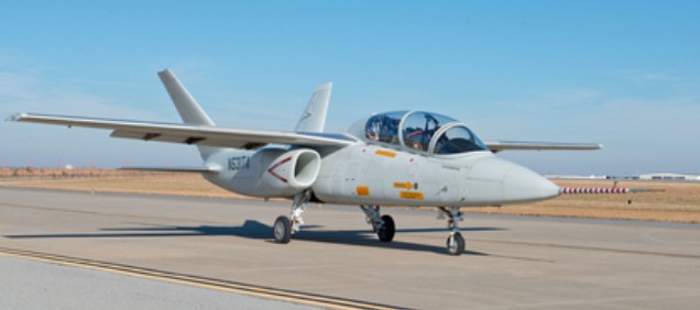
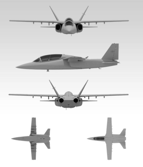
Cessna Scorpion ISR/Strike Jet / AirLand Scorpion ISR/Strike Jet / Textron AirLand Scorpion ISR/Strike Jet

Textron announced the Textron AirLand LLC and Cessna Scorpion ISR/Strike Jet aircraft in September 2013 during the Air Force Association conference.
The Scorpion is a twin-engine, low-cost jet designed for particularly areas of border and maritime security where long missions and sustained sortie rates can place a burden on dedicated tactical aircraft which were never designed for that role. The Scorpion benefits from many commercially off-the-shelf components better suited for sustained Intelligence, Surveillance and Reconnaissance (ISR) and Strike operations.
The two-seat jet is powered by twin-turbo fan engines and will be able to carry 3,000 pounds of internal payload. The all composite airframe will have an initial service life of 20,000 hours.
Textron AirLand LLC and Cessna Aircraft completed the first flight of their Scorpion jet prototype and demonstrator on December 12, 2013 from Wichita, Kansas. Textron CEO Scott Donnelly saying “When the design phase began less than two years ago, we were confident that we would deliver a uniquely affordable, versatile tactical aircraft by taking advantage of commercial aviation technologies and best practices.
The Scorpion is powered by two turbofan engines that together produce approximately 8,000 pounds of thrust. The engines are directed by a Digital Electronic Engine Control and supply conditioned bleed air to the pneumatic system. Accessories mounted on the engine gearbox power electrical and hydraulic systems. The engines can operate on Jet-A, JP-5, and JP-8 jet fuels.
The first production conforming version of the Textron AirLand Scorpion light reconnaissance/strike/training aircraft has made a successful maiden flight at McConnell Air Force Base in Wichita, Kansas, in December 2016. Experimental test pilots Don Parker and Dave Sitz carried out a series of tests on the multi-mission, twin-seater, twin-engine jet during the one hour and 42 minute flight to verify the avionics and flight performance of the aircraft as well as other flight systems.
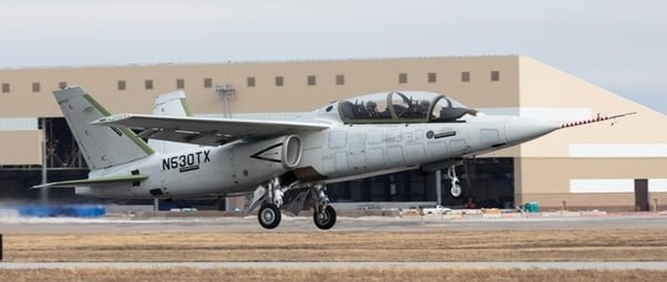
Textron says the new production version of the Scorpion has been improved based on customer feedback and 800 hours of flight testing, including military training exercises and operations in 10 countries. These upgrades include new avionics, a modified airframe, four degrees of sweep added to the wings, simplified landing gear, a next-generation Heads Up Display (HUD) and Hands-On Throttle And Stick (HOTAS) controls.
In addition, Garmin is now providing the Scorpion with the advanced G3000 integrated flight deck featuring a high-definition display and two high-definition touch-screen controllers, as well as improved navigation systems in the rear cockpit position.
The tandem-seat, twin-engine aircraft was first conceived and developed in secret in 2011 in a project to create the “world’s most affordable tactical jet aircraft.” The modular wing design allows for the wings to be replaced by different designs.
The Scorpion relies on advanced sensors and the ability to operate about 15,000 ft (4,500 m) to avoid ground fire. To keep weight and costs down, the Scorpion has an all-composite fuselage with only the undercarriage, engine fittings and mounts made of metal. Inside, there’s a 3,000-lb (1,400-kg) payload section to carry various munitions and recon gear. To simplify the design, the airframe does not include fly-by-wire systems.
Engines: 2 x Honeywell TFE731 turbo fan, 8000 lb thrust
Length: 43 ft 6 in
Wingspan: 47 ft 4 in / 14.4 m
Height: 14 ft 0 in
Empty weight: 11,800 lb
MTOW: 21,250 lb
Max internal fuel: 6000 lb
Max internal payload bay: 3000 lb
Max speed: 450 kt / 518 mph / 833 km/h
Service ceiling: 45,000 ft / 13,700 m
Ferry range: 2400 nm
Endurance: 5 hr loiter 150 mi / 241 km from base
Hardpoints: 6
Hardpoint capacity: 6,200 lb / 2,800 kg
Seats: 2
Cessna Citation M2
Cessna Aircraft Company successfully made the first maiden flight of their new Citation M2 light business jet in August 2013. The M2 departed on the two-hour flight from the company’s facility in Independence, KS.
“The aircraft performed exceptionally well today,” said Cessna production flight test pilot Terry Martindale. “We departed Independence and proceeded to an altitude of 17,500 feet. Through the almost two hour flight, we completed a large portion of the production test flight procedures. This is the first aircraft equipped with the Garmin G3000 avionics, and the system goes beyond what people might be expecting in terms of familiarity, versatility, situational awareness and ease of use. You can sense that pilots designed the cockpit. Everything is where you need it to be.”
The Citation M2 is the follow-on to the Citation Mustang jet. Offering increased speed, range, payload and avionics upgrades, the Citation M2 also features the new Garmin G3000 avionics suite, featuring high-resolution multi-function displays. Like it’s predecessor, the M2 will be powered by two Williams FJ44 turbo-fan engines.
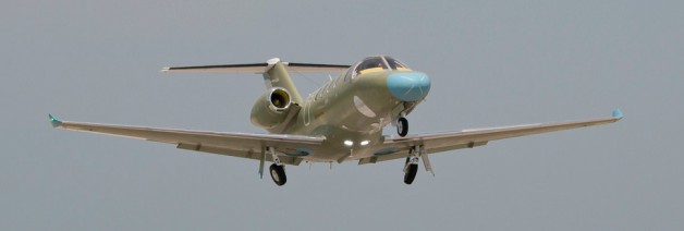
Cessna CE-510 Citation Mustang

The Cessna Citation Mustang, Model 510, is a “very light jet” (VLJ) class business jet. In its standard configuration it has four passenger seats in the aft cabin, toilet and seating for two in the cockpit. Like most other very light jets, the Mustang is approved for single-pilot operation.
Cessna CE-510 Citation Mustang Article
The Citation Mustang was first announced in 2002 and 23 April 2005 marked the first flight. FAA certification was achieved on 8 September 2006.

It utilises glass cockpit technology, having a central mounted mulitifunction display and dual primary flight display units on the instrument panel. The engines are fully FADEC equipped.
April 2007 was the first retail delivery.

Engines: 2 x 660kg Pratt & Whitney Canada PW615F turbofan
Take-off weight: 3930 kg / 8664 lb
Empty weight: 3062 kg / 6751 lb
Wingspan: 13.16 m / 43 ft 2 in
Length: 12.37 m / 41 ft 7 in
Height: 4.09 m / 13 ft 5 in
Cabin height : 4.495 ft / 1.37 m
Cabin width : 4.659 ft / 1.42 m
Cabin length : 8.99 ft / 2.74 m
Max. speed: M0.63
Cruise speed: 340 kts / 630 km/h / 391 mph
Ceiling: 12500 m / 41000 ft
Rate of climb: 917 m/min / 3000 ft/min
Range: 2160 km / 1342 miles
Crew: 1-2
Passengers: 4-5
Cost : 2,395,000 USD (2004)
Cessna CJ4
The first production Citation CJ4 took it’s first flight on August 19, 2008.
Producing an entry-level jet, the CJ1, and the progressively larger and more powerful 2 and 3 models, have proven even more successful than the original Citation. All CJs are powered by Williams Rolls-Royce engines.
Cessna Citation CJ3
The Citation CJ3 was first announced in 2002 and the first delivery was in December of 2004.
Producing an entry-level jet, the CJ1, and the progressively larger and more powerful 2 and 3 models, have proven even more successful than the original Citation. All CJs are powered by Williams Rolls-Royce engines.
Cessna CitationJet 3
Engines two 2,780-lb. Williams Rolls-Royce FJ44-3A turbofans
Length : 51.214 ft / 15.61 m
Height : 15.157 ft / 4.62 m
Cabin height : 4.757 ft / 1.450 m
Cabin width : 4.692 ft / 1.43 m
Cabin length : 20.833 ft / 6.35 m
Wingspan : 52.920 ft / 16.13 m
Empty wt. 8,160 lb.
Max take off weight : 13871.7 lbs / 6291.0 kg
Cruising speed : 417 kts / 772 km/h
Stall speed 86 kts.
Ceiling 45,000 ft
Range : 1900 nm / 3518 km
Crew : 2
Passengers : 6
Cost : 5,995,000 USD 2004
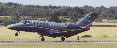
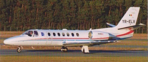
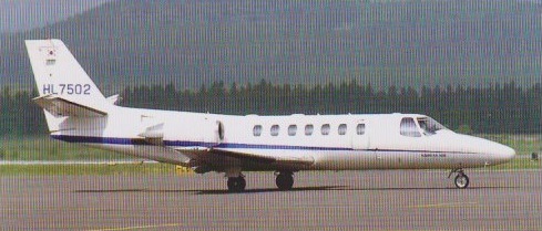
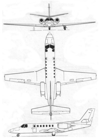
Cessna CE-560 Citation V / CE-560 Encore / CE 560XLS / Excel / Ultra
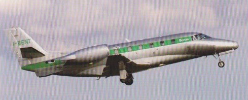
In August 1987, Cessna flew an engineering prototype of the eight-seat Model 560 Citation V This is essentially a development of the S/II equipped with 2,900 lb st / 1315kg JT15D-5A engines, and a longer fuselage fitted with a seventh cabin window. The type was certificated on 9 December 1988, first delivery made the following April and by the end of 1989 the company had delivered 33 and claimed a full orderbook for the US $3.8M Citation V to the end of 1991. More than 60 had been delivered by 1990.
Production ended in 1994 as the model morphed once again into the Citation Excel (XLS).
The Citation XLS+ was first announced in 2006. The first flight was in 2007.
The first new Cessna Citation Encore entered service on 29 September 2000 for customer demonstrations.
The Citation Encore+ was first announced in 2005.
CE-560 Citation V
Engines: 2,900 lb st / 1315kg JT15D-5A
CE-560 Encore
Engines two 3,360-lb. Pratt & Whitney PW535 A turbofans.
Seats 7-8.
Gross wt. 16,630 lb.
Empty wt. 9,977 lb
Max cruise 431 kts.
Initial climb rate 4,100 fpm.
Range 1,700-1,960 nm.
Ceiling 45,000.
CE-560 XLS
Engines two 3,804-lb. Pratt & Whitney PW545 A turbofans.
Seats 6-10.
Gross wt. 20,200 lb
Empty wt. 11,910 lb
Max cruise 429 kts.
Initial climb rate 4,100 fpm.
Range 1,700-2,080 nm.
Ceiling 45,000.
Cessna CE-162 Skycatcher
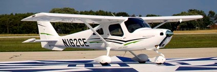
The Cessna model 162 is a certified all-metal, single engine piston, high-wing monoplane with a two-person seating capacity including the pilot.
Cessna CE-162 Skycatcher Article

Cessna registered 94 C-162 Skycatchers in 2012. The former S-LSA being a Primary Aircraft, the first such in 20 years. The switch allows it to be sold in Europe once it meets certification standards and allows a higher gross weight there: The S-LSA version was hamstrung by low payload. Sport pilots can still fly it, but must stick with the limitations of the license (no night flying, 10,000 feet max altitude etc.). Price 2012: US$149,900.

Cessna CE-162 SkyCatcher
Engine: Teledyne Continental O-200D
Time Between Overhauls: 2,000 hr
Wingspan: 30 ft (9.14 m)
Length: 22 ft 10 in (6.95 m)
Exterior Height 8 ft 4 in (2.53 m)
Max Ramp Weight: 1,320 lb (599 kg)
Max Takeoff Weight: 1,320 lb (599 kg)
Max Landing Weight: 1,320 lb (599 kg)
Usable Fuel Capacity: 144 lb (65 kg)
Typically-Equipped Empty Weight: 830 lb (376 kg)
Useful Load: 490 lb (222 kg)
Maximum Payload: 490 lb (222 kg)
Full-Fuel Payload: 346 lb (157 kg)
Maximum Cruise Speed: 118 ktas (219 km/h)
Certified Ceiling: 15,500 ft (4,724 m)
Takeoff Distance: 1,250 ft (381 m)
Landing Distance: 1,040 ft (317 m)
Rate of Climb at Sea Level: 890 fpm (271 mpm)
Range: 470 nm (870 km)
Cabin Height 46.8 in (1.19 m)
Cabin Width 44 in (1.12 m)
Cabin Length 5 ft 9 in (1.76 m)
Seating Capacity 2
Baggage Capacity 22 cubic ft (0.6 cubic m)
