Markets kits to build S-51D Mustang tandem two-seat 70 percent-scale representation of Second World War P-51 fighter.
1995-7: 3120 Airport W.Drive, Vero Beach, FL 32960, USA.
Markets kits to build S-51D Mustang tandem two-seat 70 percent-scale representation of Second World War P-51 fighter.
1995-7: 3120 Airport W.Drive, Vero Beach, FL 32960, USA.
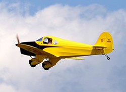
The 265 design was based on the Ryan ST and Don Stewart wanted the airplane to be in his favourite category, which included the Champ, Chief, Cub and all the rest of the 65-85 HP clan. The problem was that there was no engine available that fit the concept at the time.
A publicity release in 1993 for the Mikron III answered my need for the engine and he got down to work and finished the design work on what’s become the 265. Two people, sixty five horse power.
By December 2007, the airplane has over one hundred hours of good service with no problems other than making some new fiberglass parts to remove weight. The airplane cruises at about 90 MPH, stalls about 40 and handles very nicely. The engine burns 3.7 USgph.
Drawings were not for sale.
1961: Donald Stewart, Oconto WI., USA
Stewart Aircraft was formed in 1961 when the Headwind was designed. The name “Headwind” was derived as a bit of fun by naming it the opposite of the Whitman “Tailwind”, a very fast, two place cabin airplane. The Headwind is constructed from steel tube, wood and fabric and is a combination of several designs and concepts developed over a period of several years previous to building the airplane.
1963: Stewart Aircraft Corp, Menominee MI., USA
1977: Salem OH. USA
1980: 11420 Route 165, Salem, OH 44460, USA.
Cycle: 4 stroke
No cylinders: 4
Bore: 94 mm
Stroke: 84 mm
Compression: 9
Displacement: 2332 cc
Cooling: air
Ignition: Slick magneto
Dimension: 780 x 450 x 650 mm
Weight: 64.5 kg
Max pwr: 80 hp at 2950 rpm
Fuel consumption: 220 G/hp/hr
1998:
Via Romagna 14
I-06060 Sanfatucchio (PG)
Italy
LSA engine builder
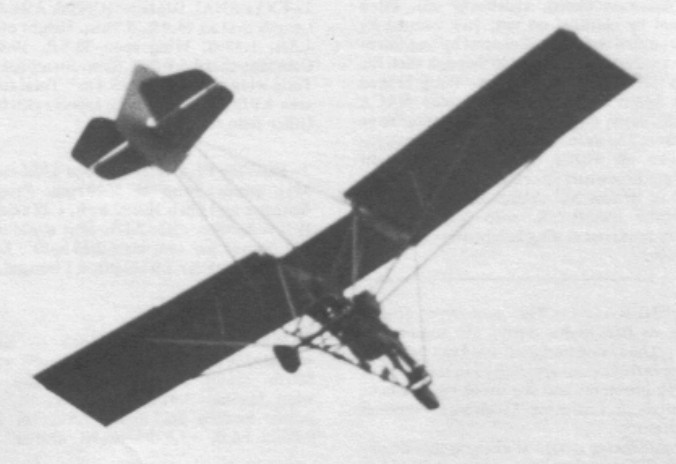
Single seat single engined high wing mono¬plane with conventional three axis control. Wing has unswept leading and trailing edges, and constant chord; flaps fitted. Cruciform tail. Pitch control by elevator on tail; yaw control by fin mounted rudder; roll control by ailerons; control inputs through stick for pitch/roll and pedals for yaw. Wing braced from below by struts; wing profile; double surface. Undercarriage has three wheels in tricycle formation. Push right go right nosewheel steering con¬nected to yaw control. Alumi¬nium tube framework, without pod. Engine mounted below wing driving pusher propeller.
In most respects the Sky Walker is a thoroughly conventional high¬wing tube and Dacron machine, powered by the Cuyuna 430. Both the aircraft and its manufacturer made their debut in 1983 and, as is becoming common with recent ultralight designs of this type, strut bracing is employed rather than the kingpost and cable bracing which has been almost universal hitherto.
Quite the most unusual feature of the Sky Walker is its use of flaps. These lift augmenta¬tion devices can be moved to four positions and at their maximum they reduce the stall speed by 3 mph (5 kph). Controls are conven¬tional three axis, with a side mounted stick controlling the elevator and differential ailer¬ons, and pedals controlling the rudder.
Price of the Sky Walker was $5495 in 1983.
Engine: Cuyuna 430, 30 hp at 6600 rpm
Propeller diameter and pitch 54 x 24 inch, 1.37 x 0.61 m
V belt reduction, ratio 2.1/1
Power per unit area 0.21 hp/sq.ft, 2.3 hp/sq.m
Fuel capacity 5.0 US gal, 4.2 Imp gal, 18.9 litre
Length overall 18.0 ft, 5.49 m
Height overall 9.0ft, 2.74m
Wing span 32.0ft, 9.75m
Constant chord 4.4 ft, 1.33 m
Sweepback 0 deg
Total wing area 140 sq.ft, 13.0 sq.m
Wing aspect ratio 7.3/1
Empty weight 253 lb, 115kg
Max take off weight 510 lb, 231kg
Payload 257 lb, 117kg
Max wing loading 3.64 lb/sq.ft, 17.8 kg/sq.m
Max power loading 17.0 lb/hp, 7.7kg/hp
Load factors; +5.0, 3.5 ultimate
Max level speed 62 mph, 100 kph
Never exceed speed 80 mph, 129 kph
Max cruising speed 62 mph, 100 kph
Economic cruising speed 50 mph, 80 kph
Stalling speed 24 mph, 39 kph (with flaps)
Stalling speed 21 mph, 34 kph (without flaps)
Max climb rate at sea level 600 ft/min, 3.1 m/s
Best glide ratio with power off 11/1
1983: Sterner Ultracraft, PO Box 811, Sterling Heights, Michigan 48078, USA.
In 2014, Robert T. Sterner Sr was the owner of Sterner Aircraft and the Skywalker.
UL builder
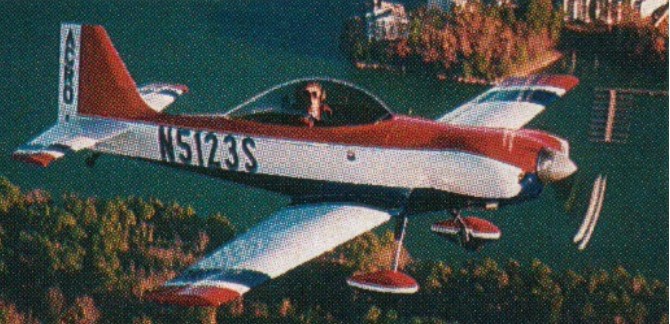
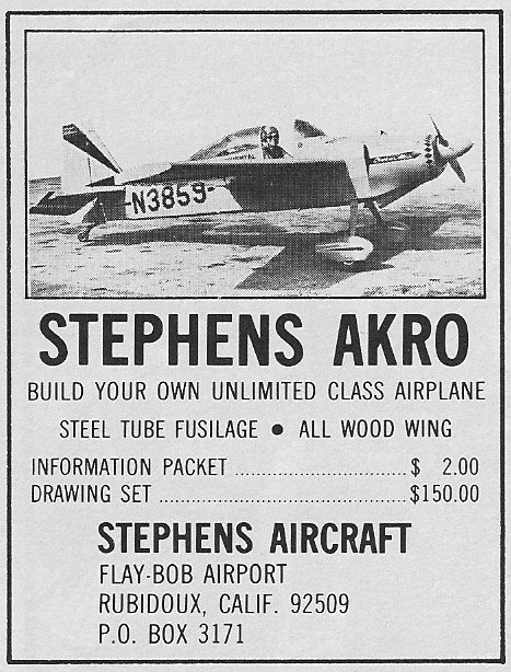
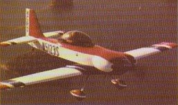
This homebuilt was designed to meet the requirements of aerobatic competition. It is stressed to + 12G and -11G. The Akro’s wing is a one-piece, all-wood structure with two spars, and its fuselage is a fabric-covered steel tube frame. Seating is for one under a sliding bubble canopy. The Model B has both a fuel and an oil system for inverted flight. The Akro is one of the most popular aerobatic ships in the monoplane class. All control surfaces are fully static-balanced.
The Aircraft Technologies Akro 1 first flew in March 1994.
Gross Wt. 1100 lb
Empty Wt. 830 lb
Fuel capacity 21 USG
Wingspan 24’4”
Length 19’
Wing area: 98 sq.ft
Engine 180-hp Lycoming
Top 192 mph
Cruise 175 mph
Stall 54 mph
Climb rate 2100 fpm
Ceiling 22,000 ft
Takeoff run 400 ft
Landing roll 900 ft
Range 375 sm
Seats: 1
Aircraft Technologies Akro 1
Engine: Lycoming IO-360, 200 hp
HP range: 100-200
Top speed: 270 mph
Cruise: 220 mph
Stall: 58 mph
Range: 1000 sm
ROC: 3500 fpm
Service ceiling: 25,000 ft
Fuel cap: 47 USG
Empty wt: 780 lbs
MTOW: 1250 lbs
Length: 17 ft
Wing span: 20 ft
Wing area: 60 sq.ft
Seats: 1
Undercarriage: tailwheel
Ultimate load: +/- 15g
Roll rate: 360 deg./sec
Aircraft Technologies Akro 1
Engine: Lycoming IO-360, 200 hp
Wing span: 6.1 m
Wing area: 5.52 sq.m
MAUW: 567 kg
Empty weight: 354 kg
Fuel capacity: 178 lt
Max speed: 434 kph
Cruise speed: 354 kph
Minimum speed: 93 kph
Climb rate: 15 m/s
Seats: 1
Fuel consumption: 40 lt/hr
Plan price (1998): $225
Kit price (1998): $22,900
c.1966:
Clayton L Stephens,
San Bernardino CA.
USA
c.1972:
Stephens Aircraft,
Rubidoux CA.
USA
1977-80: Garry M Zimmerman,
Arvada CO
USA
4265 Lilburn Industrial Way,
Lilburn,
GA 30247,
USA.
Builder of the Akro aircraft
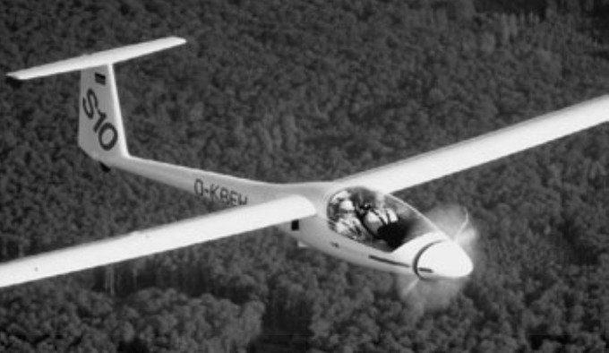
A two seat, side-by-side, motor-glider designed by Reiner Stemme, first flown in 1986, and first produced in 1990 at the Stemme factory at Strausberg Airfield, east of Berlin. The fuselage has a central steel tube frame, which forms the attachments for the wings, undercarriage and fixed internal powerplant. The carbon fibre rear fuselage bolts onto this frame, and the cockpit sec¬tion, which is a Kevlar lined carbon fibre shell, fits on the front. It has an electrically retractable undercarriage; not the conven¬tional glider mono wheel, but the more con¬ventional powered aircraft variety (although the track is quite narrow at 1.15 m). The engine is mounted behind the cockpit with a carbon shaft running through a Kevlar tunnel to a folding prop located behind a large retracting nose cone.
There are three basic varia¬tions of the Stemme, the S10, the S10V and the S10VT. The S10 has a four cylinder 93 hp Limbach four-stroke engine powering a fixed-pitch propeller. This combination gives a cruise speed of 90 knots. The S10V uses the same engine but with a variable-pitch propeller, giving a higher cruise speed of 121 knots.
The S10VT utilises a 115 hp turbocharged Rotax 914 engine, which gives a cruise speed of 140 knots at 10,000 ft. All variations a have a 23 m wingspan and can achieve a glide ratio of 50:1 while accommodating a crew of two. The three piece, 23 metre span, folding wings, contain two 45 litre fuel tanks.
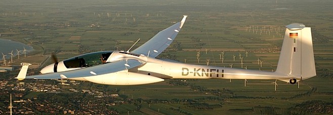
The S 10 VT engine, a 115 horsepower Rotax 914 Turbo (thus the “T” in the designation) with water cooled heads and a dual ignition system, is located in the lower fuselage be¬hind the cockpit. A centrifugal clutch turns a carbon fibre driveshaft, which is encased in a Kevlar tunnel and runs through the cen¬tral console to a reduction gearbox (0.9: 1) mounted behind the propeller in the nose section. The variable pitch (the “V” in the designation) folding propeller blades extend au¬tomatically by centrifugal force when the engine is started, with the nose cone mov¬ing forward and out of the way. When the engine is stopped, the blades fold inwards by a spring system and the nose cone is re¬tracted (which takes about six seconds) and the machine becomes a glider. The two-seater has carbon-fiber wings and solar panels for 30W of electrical power once airborne.
No. Built: 60
The U.S. Air Force Academy operates 2 S 10’s as the TG-11 A model (S 10VT), 94-1400 and 94-1500 also as civil N94FT and N94FW.
S10
Engine: 69 kW/ 93 bhp Limbach L2400 EB1. D
Wing span: 23m / 75.46 ft
Wing area: 18.74sq.m / 201.7sq.ft
Aspect ratio: 28.22
Airfoil: HQ-41
Empty Weight: 635kg / 1400lb
Payload: 215kg / 474lb
Gross Weight: 850kg / 1874lb
Wing Load: 45.39kg/sq.m / 9.29lb/sq.ft
Cruise: 90 kts
L/DMax: 51
MinSink: 0.56 m/s / 1.83 fps / 1.08 kt
Structure: GFRP/ CFRP/ Kevlar/ Steel tube
Seats: 2
S10V
Engine: Limbach, 93 hp
Prop: variable pitch
Wing span: 23m / 75.46 ft
Wing area: 18.74sq.m / 201.7sq.ft
Aspect ratio: 28.22
Airfoil: HQ-41
Cruise: 121 kts
S10
Engine: Rotax 914, 115 hp
Wing span: 23m / 75.46 ft
Wing area: 18.74sq.m / 201.7sq.ft
Aspect ratio: 28.22
Airfoil: HQ-41
Cruise: 140 kts
