Wills Wings Sport

Sport 2 175

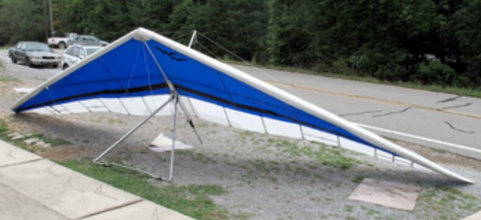
The 1987 Sport was for advanced pilots. The Sport 150 was regarded as easy to land, maybe a little tendency to accellerate when the lift arrives, but could be gentle on flat take off with little wind, if not expected. An excellent wing to progress after a single surface or a pleasure wing for less ambitious. The Sport AT 167 is the same wing except improved fittings.

Sport

The 2004 Sport 2 for intermediate pilots has almost the same sail form as the Eagle except for the curved tips. It has aerofoil uprights and speed bar. All this with a VG make the Sport 2 more performant than the Eagle, and lighter in roll. The glider lands best in nil wind with about a quarter to one third vg and lands beautifully. A great glider to progress to from the single surface sky floaters.

The Sport 2 is a very stable glider with easy and predictable flight characteristics. It tows extremely well and is stable to winching. Landing is almost too easy. Very responsive glider, it gives plenty of feedback so the different phases of the landing procedure are very obvious.

Sport 2

From the 3 available hanging points of the Sport 2 155 it was supposed to use the one in the middle. However, hanging in the middle the aerotowing was with a lot of yaw, the trim speed was 42km/h, quite more than the 30-32 kph that should be, the landing quite fast. After moving the hang loop to the rear point everything became perfect. No yawing on aerotow, 32 kph on trim, stable and straight forward, and beautiful landing. So, take care of the hanging point.

The 1986 Sport American was built in three models: 143, 153, and 163.

Sport AT

The 1986 Sport AT trapeze mounting was a bit primitive compared to the normal Sport.

Sport 167
Wing area: 15.50 m²
Wing span: 10.20 m
Aspect ratio: 6.7
Hang glider weight: 30 kg
Minimum pilot weight: 57 kg
Maximum pilot weight: 95 kg
Minimum speed: 28 km/h
Maximum speed: 85 km/h
Max glide ratio (L/H): 9.1
Max glide ratio speed: 34 km/h
Minimum sink rate: 0.96 m/s
Packed length: 4.85 m
Number of battens: 22
Nose angle: 124°

Sport 2 135
Wing area: 12.5 m²
Wing span: 8.9 m
Aspect ratio: 6.4
Hang glider weight: 24 kg
Minimum pilot weight: 59 kg
Maximum pilot weight: 73 kg
Minimum speed: 30 km/h
Maximum speed: 85 km/h
Packed length: 4 m
Packed length short: 3.4 m

Sport 2 155
Wing area: 14.4 m² / 155 sq. ft
Wing span: 9.6 m
Aspect ratio: 6.4
Hang glider weight: 27 kg / 59 lb
Minimum pilot weight: 70 kg / 150 lb
Maximum pilot weight: 97 kg / 250 lb
Minimum speed: 30 km/h
Maximum speed: 85 km/h
Max glide ratio: 12/1 at 51 Kph
Packed length: 5.1 m
Packed length short: 3.7 m
Skill Level: Intermediate
SS/DS: Double Surface
KP/TL: Kingpost
VG: Yes

Sport 2 175
Sail Area: 175 sq. ft
Glider Weight: 70 lb
Pilot Hook-in Weight: 175 – 255 lb
Skill Level: Intermediate
SS/DS: Double Surface
KP/TL: Kingpost
VG: Yes

Sport AT 150
Wing area: 14 m²
Wing span: 9.5 m
Aspect ratio: 6.3
Minimum pilot weight: 50 kg
Maximum pilot weight: 70 kg
Nose angle: 124°

Sport AT 167
Wing area: 15.3 m²
Wing span: 10.3 m
Aspect ratio: 6.8
Minimum pilot weight: 60 kg
Maximum pilot weight: 90 kg
Nose angle: 124°

Williams FJX-2

In 1996, Williams teamed with NASA to develop a small and light turbofan engine, the FJX-2, for general aviation. The General Aviation Propulsion (GAP) program was part of NASA’s 1992 Advanced General Aviation Transport Experiments (AGATE) program; a joint NASA/industry venture to revitalize general aviation.

The FJX-2 is a high-bypass-ratio turbofan engine that produces 700 pounds of thrust, yet weighs only 85-100 lb, about one-fourth the weight of piston engine propulsion systems with similar capabilities. To keep costs low, the FJX-2 team applied many lessons learned from research of automotive gas turbine engines. Emphasis was placed on simplifying design and reducing the number of parts. Low-cost design techniques and advanced automated manufacturing methods have led to the first turbine engine that is cost competitive with piston engines.

Williams F121 / WR36-1

F121

The Williams F121 (company designation WR36-1) is a small turbofan engine designed for use in the AGM-136 Tacit Rainbow anti-radiation cruise missile.

The F121 engine had a rare set of design parameters as it is designed to be used only once. As a cruise missile engine, it was designed to have a long shelf life (be able to sit around unused for long periods of time) and then operate when needed for several hours. It was designed to power the AGM-136 Tacit Rainbow, which was to be a stand-off anti radiation missile. Its first flight was on July 30, 1984. The AGM-136 program was canceled several years later.

Another unique feature of the engine is that it was started with an explosive cartridge because it couldn’t start while still mated to its aircraft.

In the late 2000s, the engine was being used by the Naval Air Warfare Center at Naval Air Weapons Station China Lake to test fuel performance and additives.

Specifications:
Type: Single Spool Turbofan
Length: 40 in (1.01 m)
Diameter: 8.5 in (0.22 m)
Dry weight: 49 lb (22.22 kg)
Compressor: 1 stage axial fan, 6-stage axial compressor
Combustors: Turboméca Piméné-type
Turbine: 2-stage axial
Maximum thrust: 70 lbf (0.31 kN)
Bypass ratio: 1.7:1
Thrust-to-weight ratio: 1.43:1

Williams EJ22 / FJ22

Williams International had been building small turbofan engines for cruise missile applications since the 1960s, and had successfully entered the general aviation market in 1992 with the FJ44 engine. That same year, NASA initiated a program, Advanced General Aviation Transport Experiments (AGATE), to partner with manufacturers and help develop technologies that would revitalize the sagging general aviation industry. In 1996, Williams joined AGATE’s General Aviation Propulsion (GAP) program to develop a fuel-efficient turbofan engine that would be even smaller than the FJ44 and designated the FJX-2 engine.

Initially, Williams contracted with Burt Rutan’s Scaled Composites to design and build the Williams V-Jet II, a Very Light Jet (VLJ) to use as a testbed and technology demonstrator to showcase the new engine. The aircraft, powered by two interim FJX-1 man-rated version of Williams’ cruise-missile engine, debuted at the 1997 Oshkosh Airshow. Development of the FJX-2 engine progressed, most of the design work was completed during 1998 with initial prototype parts being delivered in the second quarter of that year. The FJX-2 engine was designed with many experimental systems and manufacturing processes to minimize parts count and lower production costs and having a bypass ratio of 4:1. As a result, result there were many technical difficulties and failures of the initial prototype hardware. However, subsequent re-designs and the incorporation of more conventional systems resulted in the engine eventually meeting the NASA requirement of 700 lbf (3,100 N) thrust. The program ultimately culminated with altitude testing at the NASA Glenn Research Propulsion Systems Laboratory from March – April 2000.

In 2000, Williams joined with Eclipse Aviation to develop an FAA-certified version of the FJX-2, designated the EJ22, to be used on the Eclipse 500 VLJ due for first flight in June 2002. This would be an unprecedentedly short period of time to develop a new man-rated turbofan engine. The new EJ22 powered the Eclipse 500 prototype on its first flight in the Summer of 2002.

Eclipse initially required the engine to produce 770 lbf (3,400 N) thrust, exceeding the 700 lbf (3,100 N) rating of the FJX-2 by 10%. This was only the first of a large number of continuously changing requirements Eclipse would demand. Ultimately, numerous technical problems with the EJ22, significantly compounded by the frequently changing requirements of Eclipse Aviation, grounded the plane and prompted Eclipse Aviation to terminate its relationship with Williams International in late 2002. Following termination of the contract, development work and FAA certification was halted shortly thereafter.

To achieve the required TSFC, the EJ22 turbofan was designed as a three spool engine having a fan, two axial compressors and three expansion turbines. As a result, the engine was significantly more complicated than any prior Williams International engine. While very impressive on the test stand, the EJ22 proved quite temperamental during the two years of its development process and it was frequently subject to problems starting, overheating, part failures and various subsystem issues. While most of problems may have eventually been resolved during a normal development program, the shortened development period, and the frequent changes by Eclipse, proved to be unsurmountable obstacles.

The engine is a 700 lbf (3,100 N) thrust class medium-bypass ratio (4:1 bypass ratio) turbofan with a fan diameter of about 15 inches. Length is 41 inches (1,000 mm), and basic engine weight was 85 pounds. At the time of testing in March 2001 of an early EJ22 prototype the engine weighed 96 lb (44 kg) and demonstrated a thrust-to-weight ratio of 7.52. The main compressor has 6 stages, and weighs only 1.22 lb (0.55 kg). Engine layout was a three-spool arrangement, with all three compressors and turbines being axial. This was a departure from previous Williams engines, which had all used centrifugal high-pressure compressors followed by axial turbines. A reverse flow combustor and a mixed exhaust were other features.

Williams International

Walled Lake, Michigan USA
In addition to engine manufacture, has developed the V-Jet II as an engine demonstration aircraft as part of a joint NASA/industry General Aviation Propulsion Program, intended to assist the U.S. light aircraft industry through turbofan technology. V-Jet II first flew April 1997 as a fiveseat jet of composites construction.
In 2010, Williams was in the component design phase of the engine technology program, is emphasizing low cost manufacturing processes suitable for high quantity production, and is active with key suppliers to minimize material and purchase parts costs. The new Williams engine has been named the “FJX-2.”
Dr. Sam Williams, Chairman of Williams International, said, “Our objective is to replace aging, piston-powered light aircraft with all new, four-place single and six-place twin, turbofan-powered modern aircraft. This means we must develop a turbofan in the 700 lb thrust category that is very low in cost at a high production rate, is extremely quiet, is light in weight, and is very reliable.”

Williams Mk.4

As the designation infers, the Williams Mk.4 is the fourth aircraft from the hands of the late Geoff Williams, a well-known Otago identity who did not like to conform to the rules. It was finished about 1990, first flew in 1991 and had logged over 160 illegally flown hours prior to its sale to Bob Gibson in June 2002. This aircraft was legally registered as ZK-JPA on 25 February 2003.
Geoff Williams never flew again after the third aeroplane, but resolved to build a fourth aircraft. This is the aircraft Bob Gibson bought. This plane was not difficult to fly he did have a few minor landing faults.
Geoff’s ambition was to fly his aeroplane around Fiordland coastline, landing at somewhere like Jackson’s Bay for refuelling and to this end he built a heated cabin and fuel capacity of over 100 litres and a locker where he could hold an additional 10- or 15-litre can. Sadly this was never to be realised as Geoff became ill March 2002 and died on 10 May 2002. It was Geoff’s wish that his plane be kept flying, and Bob seemed to be the person most interested.

Wingspan: 30 ft
Engine: Rotax 447
Prop: 3-blade Warp Drive
Cruise: 60 kts
Stall: 22 kts
Seats: 1
ROC: 500 fpm
Fuel burn: 12 lt/hr

Williams WACO RTO

An 80% scaled replica version of the Waco ATO. Construction began in May 1983.
The four wing panels are identical but required 48 ribs built during 1983. Each panel contains 12 truss type spruce ribs, and the 6 foot centre section has nine constant chord ribs. The wings retain the original M-6 profile. The chord of the centre section ribs is 4 ft 1.5 in, and outboard ribs 2 ft 10.5 in. The spars are solid planks, the forward being 5 x 11/8 in and the rear spar 4 x 1 inch. The four ailerons each have six ribs and are equal span and chord. The wings are braced with dual straight 4130 steel outboard struts and N centre section struts, and streamlined stainless steel wires. The fuselage and tail components are welded 4130 with wood formers and stringers in the fuselage and wood fairings at the fin and stabiliser roots.
The tail spans 8 ft 10 in and rudder stands 3 ft 3 in. Rudder and aileron are cable controlled and the elevator through torque tubes. The main undercarriage is a welded outrigger type with Cleveland brakes, and a 5 ft 2 in tread. A Scott 3200 tailwheel holds an 8 inch tyre.
The first flight was in August 1987. Total cost: approx US$15,000.

Engine: Warner Super Scarab, 165-175 hp
Prop: Aeromatic 85 in
Seats: 2
Empty wt: 1085 lb
Loaded wt: 1630 lb
Wingspan: upper 24 ft lower 22 ft
Length: 18 ft
Height: 7 ft 2 in
Fuel cap: 31 USG
ROC 2500 fpm @ 70 mph
Cruise 65%: 105 mph
Stall: 55 mph

Whittaker MW-7

The MW-7 is a scratch-built only, single seat, aerobatic microlight. Designed in 1986, the wing area was too small for the UK ultralight category. Construction is tube and fabric. The wings can be folded. Designed to meet British section PPL-A requirements in accordance with ARB paper 98 aerobatic requirements.

By 1998 ten examples had flown.

Plans were being sold be the Vintage Ultralight Association.

Engine: Rotax 503, 52 hp
HP range: 52-65
Length: 15 ft
Wing span: 22 ft
Wing area: 88 sq.ft
Empty weight: 320 lb
Gross weight: 600 lb
Fuel capacity: 5-10 USG
Vne: 110 mph
Cruise: 55 mph
Stall: 35 mph
Rate of climb: 800 fpm
Takeoff dist: 150 ft
Landing dist: 125 ft
Service ceiling: 15,000 ft
Seats: 1
Landing gear: tailwheel
LSA: yes

Engine: Rotax 503, 50 hp
Wing span: 6.70 m
Wing area: 8.20 sq.m
MAUW: 273 kg
Empty weight: 145 kg
Max speed: 185 kph
Cruise speed: 120 kph
Minimum speed: 65 kph
Climb rate: 5.1 m/s
Seats: 1
Plan price (1998): £60