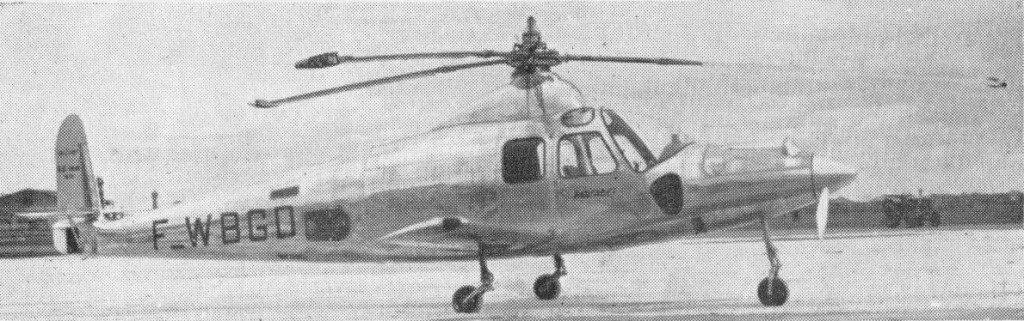
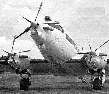
This is the first French convertible. It can take off vertically, hover in the air, land vertically by means of its rotor, and fly forward at a speed greater than that of pure helicopters by means of a fixed wing and an airscrew fully independent of the rotor.
The change from one state to the other is accomplished without any change at all in the external appearance. The SO.1310 is provided with two independent power units. In the rear is an Arrius II 360hp Turbomeca unit, which supplies the jet rotor with compressed air at take-off. The all-metal three-bladed rotor is identical with the one used in the SO.1120 Ariel III, but with a larger diameter.
In the forepart there is a Turbomeca Artouste II turbo-prop engine with a take-off power of 360 hp, operating a variable-pitch airscrew. During forward flight, the rotor originally used for take-off continues to auto-rotate, but with low lift, and the greater part of the lift is transferred to the fixed wing. Mounted over the fixed wing is the pilot’s cabin, fitted with dual control, and in this cabin there is room for either three passengers, a freight load or two stretchers stacked on top of each other.
The Farfadet single prototype F-WBGD first flew on 8 May 1953. Its maiden flight, lasting about twenty minutes, was made as a true helicopter, the following one, on the same day, with the rotor and the airscrew respectively powered by their individual engines.
SO.1310 Farfadet Engine: 1 x 360 hp Turbomeca Artouste II gas turbine & 1 x 360 hp Turbomeca Arrius II gas turbine Rotors: 3-blade tip-powered main rotor; 2-blade propeller Rotor diameter: 11.2m / 36 ft 6 in Wingspan: 6.3m / 19 ft Fuselage length: 10.08m Height: 3.3m Weight fully loaded: 1510kg Empty weight: 995kg Cruising speed as a helicopter: 155km/h Cruising speed as an autogyro: 250km/h Range: 400km / 250 miles at 149 mph Seats: 3
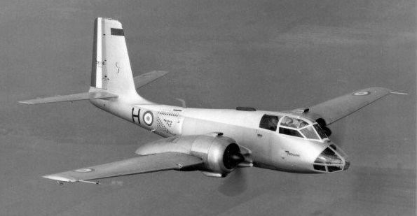
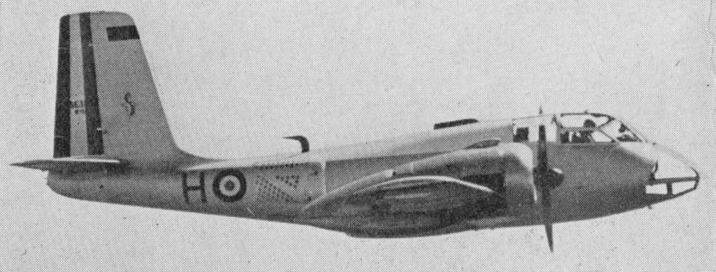
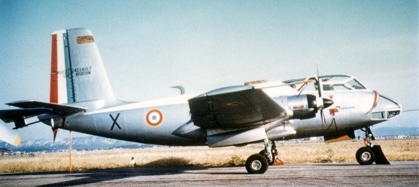
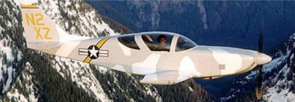
The Sud-Aviation SE-116 Voltigeur was designed to a French Air Force specification for a ground support aircraft. The first flight was made on 5 June 1958.
The SE-116 was a piston-engine fore-runner of the turbo-prop SE-117 which competed with the G.A.M.D. 410 Spirale for orders from the French Armed Forces.
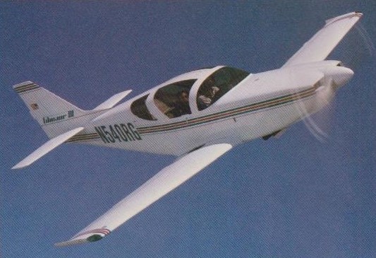
1986 marked the introduction of the Glasair III, two-place sportplane on the planet. Powered by its 300 h.p. Lycoming IO-540 to cruise speeds in excess of 265 m.p.h., the kit featured all the new labor-saving innovations of the Glasair II kits.
The Glasair III Aircraft kit includes virtually everything you need to complete the airframe, including cowling and engine mount. You supply the powerplant, propeller, upholstery, paint, instruments, avionics and electrical system. In 1988 the price, less engine, instruments, prop, and upholstery, was US$32,500.
People who have shopped around and compared the Glasair with other kits have discovered that the precision fit of Glasair parts, the degree of completion of small parts or subsystems and the attention to details in the assembly process make the Glasair kits truly fast to build. The aircraft is assembled from preformed composite shells. This process assures accuracy and virtually eliminates the need for any complex jigging fixtures.
The resin used on the Glasair is a type of vinylester resin that has a maximum heat distortion temperature of 300 degrees F. Vinylester resins offer a number of advantages and benefits over epoxy-based systems. Some of these benefits include: superior secondary bonding characteristics, avoidance of skin sensitivity problems, longevity and reliability.
All welding is factory finished and protective coated. All Glasair fabricated metal components are already machined or formed and are coated per military or aerospace specifications for maximum corrosion resistance. The fuselage comes in two large half-shells and three belly sections. Recessed flanges at the fuselage/cowl split line are designed to be stronger and make installation easier, creating a perfectly flush cowling. Piano hinges and Camloc fasteners are used to allow easy cowling removal for engine inspection. There are molded scribe lines for the wing and horizontal stabilizer cutouts, eliminating the guesswork and time involved in layout and measuring.
Low drag NACA-style cabin air vents are included, which are easily installed by the builder. Fuselage shells feature factory molded longerons sandwiched between the skins that substantially increases the strength and bending stiffness of the fuselage. Precision recesses accommodate windshield, canopies, and rear window installations.
Wing configuration is designed for the widest possible range of high and low speed operations. Dimensionally, the Super II and III wings are identical. Structurally, they vary to accommodate different weight and speed envelopes. Glasairs are not subject to the high speed stalls, hot approaches and long rollouts that characterize most high performance aircraft. Short, grass or gravel field capability were a must in designing the Glasair. The wings were designed to achieve slow speed performance and maintain good penetration in turbulence over 200 mph. They also achieve a good degree of laminar flow, yet have no undesirable characteristics when flying through rain.
The one-piece wing incorporates solid fare and aft I-beam spars spanning wingtip to wingtip, eliminating failure modes associated with three piece wing designs. Both spars have sturdy, machined attach fittings that fasten the wing to the fuselage, enabling removal of the wing to facilitate repair, inspection, or when transporting the aircraft to the airport for the initial flight.
Both Glasair models have time-saving premolded recessed attach flanges for the inspection covers and wing tips. The fuel sump is premolded into the lower wing skin and the seat pan cut-out area is scribed for easy removal. The Glasair III comes with molded gear door flanges to insure an accurate flush door fit. Wing tips for the Super II and III have an upswept Hoerner-type trialing edge to provide improved lateral stability and to reduce induced drag. The tips feature premolded, recessed flanges for the red and green navigation light lenses which easily bond to the flange and fit flush with the external surface.
Wing tip extensions add approximately 24 inches to each side, increasing the wing aspect ratio. In 20 minutes you can change from extended wing tips to standard tips. Economy cruise performance at 17,500 feet increases by 7 mph and stall speed drops by about 6 mph. Climb performance increases by 150 fpm and roll stability is improved.
Time-saving features have been implemented into the Glasair Super II and III empennage sections. The horizontal stabilizer and elevator are formed in separate molds with matching elevator counterweight cutouts molded into the horizontal parts. Horizontals for the Glasair III are a carbon graphite fiber/E glass hybrid for appropriate stiffness.
The elevators are manufactured with factory reinforced molded counterweight arms for necessary strength requirements. They are installed using centerline hinging which provides a symmetrical airfoil when the elevator is deflected either upwards or downwards. An independent manual trim system provides elevator back-up control and works on a simple worm gear mechanism. An optional electric trim is also available for all models. Rudders for the Super II and III have premolded counterweight arms which match perfectly to the vertical fin for a close, low-drag fit. Tail light assemblies are also premolded into the rudder parts.
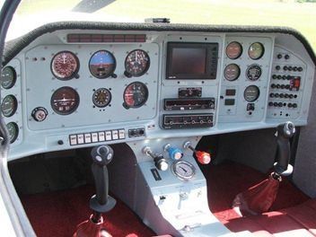
Glasairs use a conventional, three-axis, dual stick control system for pitch and roll, and dual rudder pedals for yaw. Mechanical or optional electric slotted flaps are employed for slow flight and can be set from 0 to 34 degrees. Solid push-pull tube linkages are used between the cockpit controls and the control surfaces themselves. Aircraft grade self-aligning rod and bearings used with the solid linkages give the Glasair smooth, positive control response. Stainless steel cables link the foot pedals to the rudder.
The slotted flap installation reduces stall speed by 6 mph, reduces landing and takeoff roll, significantly improves landing visibility during approach, reduces approach speeds, and increases maximum flap speed from 120 to 140 mph.
Both the ailerons and flaps are designed to allow tight surface gaps thus reducing drag even further. These controls are hinged on the lower surface with extruded aircraft piano type hinge.
There are two fuel tanks in the Glasair: one main tank in the front D-section of the wing and a header tank aft of the firewall. An engine driven mechanical fuel pump and an electric auxiliary pump supply fuel to the carburetor or fuel injector. The Glasair III has additional fuel bays in the wing, allowing greater fuel capacity. Tank baffles and one-way valves are installed to prevent fuel sloshing. Fuel sumps with drains are located at the bottom of each tank. The fuel vent system includes fuel vent float valves that help prevent fuel spills while parked on uneven ground or while flying inverted during aerobatics. Glasairs include the complete fuel system from fuel tanks to the carburetor or fuel injector in the kit.
Nontoxic Rohacell foam is used as the core material in the composite firewall bulkhead. A one-half inch thick sheet of ceramic fiber insulation, which is protected from engine oils by a lightweight alumimum sheet, provides fireproofing and noise insulation on the forward side of the firewall. This firewall withstood the FAR Part 23 2000 degrees F 15-minute burn test.
Both Glasair II and III models feature a dual gullwing canopy system. The canopy frames are supplied premolded and factory assembled to form lightweight, rigid frames.
S-H introduced the Glasair III Turbo in 1990. A complete firewall-forward package, this option pushed the standard Glasair III airframe up into the Flight Levels at speeds of well over 300 m.p.h.
The Glasair III LP was displayed at the NASA exhibit in Oshkosh in 1993. The result of S-H’s participation in a NASA-funded Small Business Innovation Research (SBIR) grant, the LP was the first lightning-protected composite kit aircraft. Under the terms of the SBIR grant, the research results produced in the course of this project became part of the public domain, and future certified composite aircraft such as the Cirrus and the Kestrel utilize technology based on S-H’s findings. S-H continues to participate in several other SBIR grants and NASA advanced research programs on such topics as composite manufacturing techniques and aircraft crashworthiness.
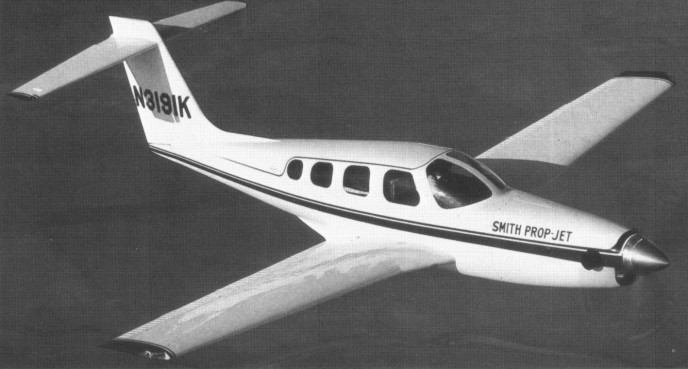
The Glasair III Prop Jet also debuted at Oshkosh ‘94. Built by Composite Turbine Tech, Inc., of Toledo, Washington, this aircraft mated a 450 s.h.p. Allison 250 B-17 turbine engine to a standard Glasair III airframe with a larger rudder. First flying on 24 July 1988, the prototype N253LC, was developed in association with Arocet Inc, Arlington WA (pres: Tom Hamilton), as a low-cost military trainer.
Kits for both the III and the Super II underwent upgrades in 1995, as previously optional equipment was incorporated into the standard kits. Ever-increasing degrees of factory prefabrication, part quality and kit completeness continue to be the hallmark of the Glasair line.
Following a sophisticated computational fluid dynamics analysis of its aerodynamic qualities at speeds in the Mach .6–.7 range, the Glasair III got an enlarged rudder, a new cowling and a mighty turbocharger to become the Glasair Super III in 1998. Designed to produce 350 h.p. at altitudes of up to 37,000 feet, the new powerplant testing on the prototype had been flown to 35,000 feet at airspeeds of greater than 320 knots. At 32,000 feet, the aircraft was still capable of climbing at over 2,000 feet per minute.
Original manufacturer of the Glasair and Glastar, Stoddard Hamilton closed its doors in 2000 after more than 20 years in business. Both aircraft types were split from the Stoddard Hamilton camp when the clo-sure occurred.
Thomas W. Wathen, former Chairman and CEO of Pinkerton’s, Inc., purchased the assets of Stoddard-Hamilton and AADI and formed Glasair Aviation, LLC in 2001 for the continued manufacturing and sale of both the Glasair and Glastar product lines.
New owner Thomas Walthem was committed to getting all three kits back into production. He initially purchased the Glasair side of the business but after fining the overheads of the line were not self supporting approached Arlington Aircraft Development Inc (AADI) to purchase the GlaStar line. As a single entity, the Glasair and Glastar kit aircraft under the banner of New Glasair/GlaStar.
In 2009 still produced kits to construct the Turbine 250/III turboprop two-seater, and T-9 Stalker two-seat turboprop variant of Glasair III as trainer (first flown 1988).
The first flight of Soloy Corporation’s modified Cessna 208B Cara¬van, Pathfinder 21, was successfully made on 30 April at Olympia, United States. Flying the aircraft was Soloy’s chief test pilot Paul Haggland and on board for the milestone was crew chief Dan Wright and company president Joe Soloy. The Pathfinder 21 is equipped with two Pratt & Whitney Canada PT6D-114A engines powering a single propeller. The arrangement incorporates a Soloy Dual Pac gearbox assembly, which was certified by the FAA on 18 November 1997. The aircraft’s wings, struts and landing gear have been reinforced to enable its gross ramp weight to be increased to 5,675 kgs (12,500 lbs). The aircraft’s fuselage length has also been increased to almost 2 m more than Cessna’s design.
Engines: 2 x Pratt & Whitney Canada PT6D-114A Max ramp wt: 5,675 kgs (12,500 lbs)
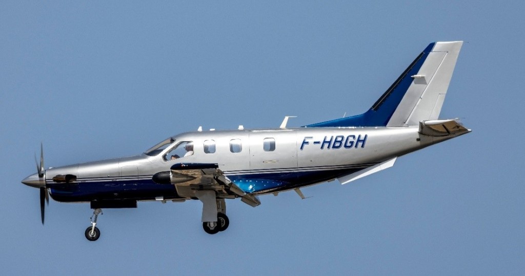
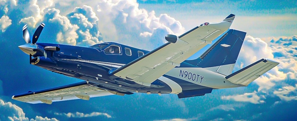
Launched in June 1987, the TBM 700 is a pressurised single-engined business aircraft developed by TBM International, formed by Socata (France) and Mooney (USA): Valmet (Finland) joined the programme in 1988. Production is split between the partners for assembly in France. The long nose cowling houses a 700 shp (522 kW) Pratt & Whitney Canada PT6A-40/1 turboprop driving a four-bladed propeller. Three were built, the first of which made its initial flight on 14 July 1988, and production aircraft were flying by 1990.
With a maximum cruise speed of around 300 knots and a range exceeding 1,500 nautical miles, the TBM 700 quickly became a favourite among business travellers and private owners looking for a high-performance aircraft with good operational flexibility. According to the April 2023 edition of Flying Magazine, the first production batch of 50 TBM 700s sold out almost instantly.
The engine in the TBM 700A is classified as a large PT6A, the “dash 64” which is derived from the 67 gas generator and the 42 propeller gear¬box. The gas generator operates at about half power and the gearbox should never see more than 82 per cent of its rated capacity as the TBM 700 installa¬tion calls for only a 700 h.p. output. The fuel control unit stops the engine producing more than about 800 h.p. and the pilot, by observing the torque and temperature limits, limits the output to 700 h.p. The TBM 700A aerofoil RA16 43 is the same computer designed, wind tunnel tested wing of the ATR 42 and ATR 72 regional airliners. In the TBM 700A’s role as an executive aircraft it is superb with its comfortable cabin, its pressurisation (6.2 psi diff.) that can maintain a sea level cabin to 14,500 ft aircraft altitude and an 8,000 ft cabin at 29,000 ft. It’s fast, it has excellent airfield capability.
Its pressurized cabin allowed it to cruise at altitudes up to 31,000 feet, making it ideal for long-distance flights. Over its production run, several upgrades were introduced, improving avionics and cabin features.
TBM 700
The TBM 700B featured a wide entrance door and increased maximum zero fuel weight.
The TBM 700C1 featured rear unpressurized cargo compartment, reinforced structure, and new air conditioning system.
The TBM 700C2 had an increased maximum takeoff weight.
The TBM 700C2 aircraft can cruise at over 30,000 feet at 225 knots, has a range of 1,565 run (with a 45 minute reserve), and is fitted with dual Garmin GNS 530. The GNS 530 combines IFR GPS receivers with large colour moving maps and has a digital 3,040 channel communication system and ART RDR 2000 weather radar.
The TBM 700S features a 3 ft 7 in longer fuselage.
Snow Aviation International Inc was founded 1990 to develop twin-turboprop commercial SA-204C STOL passenger/cargo transport and military SA-21 OAT derivative.