The Tu-95 was developed for use by the Soviet Union’s DA (Long-Range Aviation) as an intercontinental strategic bomber. Design of the Tu-95 version began before 1952, powered by four Kuznetsov NK-12 turboprop engines, the bench-testing of which started in 1953.
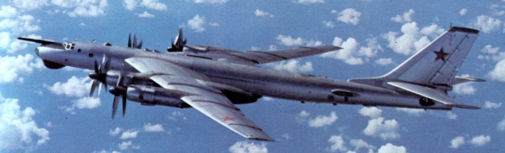
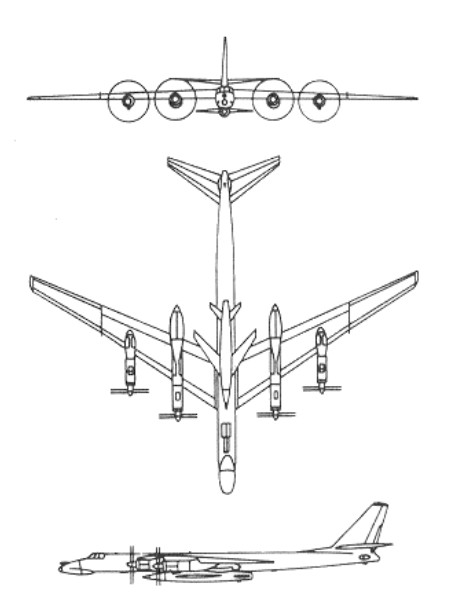
Making use of identical systems, techniques and even similar airframe structures as the Tu-16, the Tu-95 (service designation Tu-20) is much larger and has roughly double the range of its turbojet predecessor. The 35 degree swept wing, formed integral tanks, with turboprop engines and their eight blade 18 ft 4½ in (5.6 m) contraprops. Sweptback tail surfaces have an adjustable-incidence tailplane. Conventional control surfaces are supplemented by spoilers in the upper surface of the wings forward of the ailerons. Fowler-type trailing edge flaps are fitted. The tricycle undercarriage, with twin nose wheels and a four-wheel bogie on each main unit all retract rearward, plus a small two-wheel retractable tail-bumper,
The basic bomber called “Bear A” by NATO had a glazed nose, chin radar and gun-sight blisters on the rear fuselage. First seen in 1961, “Bear B” fea¬tured a solid nose with enormous radome, refuelling probe and centreline attachment for a large cruise missile (‘Kangaroo”). C appeared in 1964 with a large new blister on each side of the fuselage (on one side only on B). while D was obviously a major ECM/FSM reconnaissance type with chin radar, very large belly radar, and from 12 to 21 avionic features visible from stem to stern. F is a multi-sensor reconnaissance conversion of A. while F is a recent further conversion with an array of ventral radars and stores bays in place of the ventral guns. Older Tu-95 Bear A and B variants are being converted to carry the supersonic AS-4 Kitchen air-to-surface missile in place of the AS-3 Kangaroo. Modified aircraft are codenamed Bear G by Nato.
First flown in prototype form on 12 November 1952, the aircraft was allocated the service designation Tu-20, and began to enter service with the DA bomber force in 1955. Its turboprop powerplant gives remarkably high speed and, at the same time, long range and endurance. Additionally, the large size of the Tu-95 has permitted the carriage of extensive radar equipment and the largest Soviet air-to-surface missiles and bombs.
Built up to 1992, the total production run was fewer than 300.
In 1984 DA (Long Range Aviation) had an ultra long range backbone comprising 113 bombers called ‘Bear A’ and ‘Bear B’ by NATO.
The AV MF had 75 of various types used for ocean patrol, anti ship attack, and ECM/EW.
The crew in all versions is accommodated in nose and rear fuselage pressurized cabins, as well as the pressu-rized but isolated rear turret, fitted to most versions. Most operational variants have an inflight refuelling probe on the nose, but even on internal fuel it is possible to fly missions lasting 26 hours. Some models, such as the ‘Bear D’ maritime surveillance aircraft, are packed from nose to tail with radars, navaids, special com-munications, missile guidance links and other advanced electronics.
Engines: 4 x turbo-prop NK-12M, 11030kW Max take-off weight: 185000 kg / 407857 lb Empty weight: 94400 kg / 208117 lb Wingspan: 51.0 m / 167 ft 4 in Length: 49.0 m / 161 ft 9 in Height: 13.0 m / 43 ft 8 in Wing area: 310.0 sq.m / 3336.81 sq ft Max. speed: 860 km/h / 534 mph Cruise speed: 710 km/h / 441 mph Ceiling: 11000 m / 36100 ft Range w/max.fuel: 15000 km / 9321 miles Crew: 10 Armament: 2-6 x 23mm cannons Bombload: 20000kg
Engine: 4 x NK-12MV turboprops, 14,794 ehp Wing span: 159 ft (48.5 m) Length 155 ft 10 in (4750 in). (certain versions differ by up to 6 ft.) Height 38 ft 8 in (11.78 m) Maximum speed (typical Bear clean) 540 mph (870 km/h) Service ceiling, about 44.000 ft (13,400 m) Range with 25,000 lb (11.340 kg) bomb load. 7,800 miles (12,550 km) Armament: normally six 23 mm NS-23 in radar-directed manned tail turret and remote-aimed dorsal and ventral barbettes (defensive guns often absent from late conversions and from Moss); internal weapon bay for load of about 25,000 lb (11,340 kg).
Tu 20/Tu 95 ‘Bear A’ Type: strategic bomber Crew: 8 Powerplant: four 14,795 ehp (11033kW) Kuznetsov NK 12M turboprops Max speed: 950 km/h (590 mph) at high alt Service ceiling: 14000 m (45,930 ft) Range with bombload: 17500 km (10,875 miles) Wing span: 51.10 m (167 ft 7.75 in) Length: 49.50 m (162 ft 4.75 in) Height: 12.12 m (39 ft 9 in) Wing area: 310.50 sq.m (3,342.3 sq ft) Fuel capacity: 73,000 lt Armament: two internal bays for a total bombload of 20000 kg (44,092 lb), plus a defensive armament of four (or, with rear dorsal, five) powered turrets each with two 23 mm NR 23 cannon.
At the end of the 1940s, the Soviet government took a decision to expand the Voenno Morskoi Plot (VMF, the Navy). It was decided to include an aircraft carrier fleet, and development of aircraft suitable for carriers was a part of the programme. Tupolev was given the task of designing a strike aircraft for the new fleet.
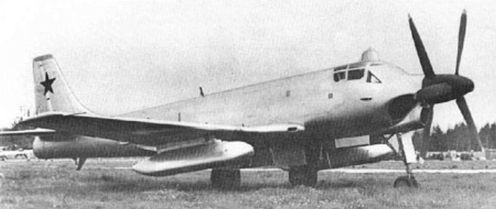
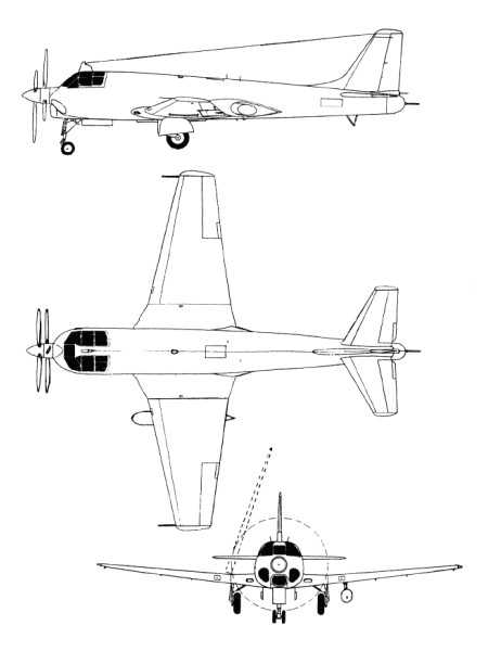
Vladimir Chizhevski was appointed chief designer. His team developed a two-seat low-wing monoplane, with a straight wing and with the engine located in the centre fuselage driving a long propeller shaft, which ran through the middle of the cockpit, and drove, through gears, two contra-rotating three-blade propellers.
Josef Stalin died in March 1953, and the new leaders cut back the VMF expansion plans and thus the requirements for carrier-borne aircraft was cancelled. The naval chiefs, however, still saw a need for a strike aircraft, and Tupolev was asked instead to prepare a land-based aircraft for the role. This time Chizhevski was requested to design a dive bomber for attacking naval surface and submarine vessels; instead of carriers, it had to be capable of operating from runways of limited length.
The Tu-91 required only relatively minor changes to meet the revised needs. The folding wings were now unnecessary and, with the arrestor hook, were removed and were replaced with conventional wings.
The test programme began in autumn 1954 and went well. Both the factory tests and the state tests gave good results, and the aircraft was approved for production. Only the politicians remained to give their approval. In the summer of 1956, the latest examples of military aviation were unveiled to a group of high level officials, including the new General Secretary of the Communist Party, Nikita Khrushchev. Among all the gleaming examples of power and speed was the straight-winged Tu-91, one of very few propeller aircraft present and looking awkward in comparison with its neighbours. ‘What’s that?’ Khrushchev asked a naval officer attending the aircraft. Confused momentarily by being addressed by Khrushchev, the officer, instead of replying that the aircraft could deliver firepower equal or greater than that of a heavy cruiser, answered that it could do the job of a cruiser. The jovial Khrushchev then asked: ‘So why do we need cruisers?’
The career of the Tu-91 was over. Although Tupolev used all his connections and experience it was impossible to gain support from those under the leader.
Engine: 1 x TV-2M turboprop, 7650hp Max take-off weight: 14400 kg / 31747 lb Wingspan: 16.4 m / 54 ft 10 in Length: 17.7 m / 58 ft 1 in Height: 5.06 m / 17 ft 7 in Wing area: 47.48 sq.m / 511.07 sq ft Max. speed: 800 km/h / 497 mph Ceiling: 11000 m / 36100 ft Range: 2350 km / 1460 miles Crew: 2
The association between France and Germany that has produced the Transall began when the German aircraft industry built the Nord 2501 Noratlas under licence for the Luftwaffe. The successful co-operation between the Weserflugzeugbau GmbH and Nord Aviation on the Noratlas programme led to both companies studying a follow-on project for this old-fashioned twin-boom piston-powered medium transport. The “Transporter-Allianz” was formed in January 1958 by the participating companies, Transall being an abbreviation of the name, while the letter “C” stood for “Cargo” and the figure “160” for the equivalent wing area of 160 square metres. The joint team designed a tactical cargo and troop transport in the 50-ton category to fulfil the joint requirements of the French and German forces, with the capability of hauling a 17,600-1b (8 000-kg) payload out of semi-prepared fields over a radius of 750 miles (1200 km) without refuelling.
After several individual concepts had been studied separately in both countries, the Transporter Allianz concentrated on a shoulder wing design with two Rolls-Royce Tyne 20 Mk 22 turboprops of 6,100 eshp each, with a rear loading ramp and a kneeling landing gear to lower the fuselage for loading. According to the bi-national contracts signed in December 1959 and March 1960, the R & D costs were to be divided equally between France and the Federal Republic of Germany while each country would pay for the number of aircraft ordered for its specific needs, and final assembly lines would be established in each country.
The first prototype, the C-160 V 1, was assembled in France and made its maiden flight on 25 February 1963 at Villaroche, the V2, assembled by VFW Fokker, following exactly three months later at Lernwerder; the V3 flew on 19 February 1964 in Hamburg, (two separate assembly lines having been set up in Germany by MBB and VFW). Also in 1964, the airframes for static and dynamic tests were completed. An additional six pre-series aircraft were built before production started, with the first delivery on 2 August 1967. France had meanwhile ordered 50 Transalls (C- 1 60F), Germany ordered 110 (C-160D), 20 of these being later passed to the Turkish Air Force (as C-160T), and the Republic of South Africa bought another nine (C-160Z). The six pre-series aircraft were divided between France and Germany.
As far as the production breakdown is concerned, Nord Aviation was responsible for the wings and engine nacelles, Hamburger Flugzeugbau (HFB) built the front and rear sections of the fuselage and Vereinigte Flugtechnische Werke (VFW) the central fuselage and the horizontal tail surfaces. Some wing parts and the flaps were sub-contracted to Messerschmitt and Siebel ATG while Dornier built the vertical tail surfaces. The Messier-designed landing gear was coproduced with Liebherr-Aerotechnik. Rolls-Royce cooperated with Hispano-Suiza (now a branch of Snecma, France), MAN (later Motoren- und Turbinen-Union, Munich) and FN (Belgium) in manufacturing the Tynes. Ratier-Forest in France produced the big 18-ft (5,49-m) diameter four-bladed de Havilland propellers and Normalair (UK) delivered the pressurisation and air conditioning systems. VFW was the lead company in the programme.
The shape and dimensions of the fuselage were essentially designed to conform with the “International Railway Loading Gauge” over the entire length of the hold. The length of the compartment including the ramp is 56 ft 6 in (17,21 m), the useful width is 10 ft 4 in (3,15 m) and the max useful height 9 ft 9 in (2,98 m). The floor area is 583,9 sq ft (54,25 sq.m), giving a usable volume of 4,940 cu.ft. (140 cu.m).
Thus, a total of 178 Transalls had been produced when the last aeroplane rolled off the assembly line in October 1972. Deliveries totalled 52 C 160F for the Armee de l’Air (four modified as 160P civil night mail transports), 110 160D for the Luftwaffe (20 later transferred to the Turkish air force and 32 stored) and nine 160Z for the South African Air Force.
51+02 LTG-63 Hohn A/B, Dec 1986
The Transall C-160 was designed for flexible payload-range capabilities and stringent mission requirements. These include high gust and manoeuvre loads of 3 g at low level, as well as high static loads on landing gear and structure encountered in rough, semi-prepared field operations. The fuselage is built in three units, with the usable section designed for an operating pressure of 4.7 psi. In the centre section of the fuselage, seven main wing-fuselage frames made of forged and plate components carry the loads from the wing and the landing gear. The fuselage skin is stiffened by extruded Z section stringers. Heavy corrugated aft-fuselage frames in the tailplane take up the forces from the tail unit and the aft upward hinged cargo door.
The wing comprises three major components, a parallel chord centre section to which are bolted two tapered outer panels. The primary structure is a wing torsion box with two shear-web spars to which are attached the leading- and trailing-edge sub-assemblies. The upper and lower wing skin panels are stiffened with longitudinal extruded T-section stringers. Double-slotted flaps, spoilers, airbrakes and ailerons make up the moving surfaces of the wing. The tail unit consists of a three-spar, fully cantilevered horizontal stabiliser and a three-spar fin torsion box with stiffened skin construction. Elevator and rudder are of the same conventional construction. The dorsal fin consists of aluminium sandwich flat panels.
The main landing gear has eight wheels, with two tandem pairs of wheels on each side. Together with low pressure (55 psi) tubeless tyres sized 15.00-16, the resulting single wheel loads provide the aircraft with an excellent ability for operations from semi-prepared or unprepared strips. The twin-wheel low pressure (45 psi) nose gear is hydraulically steerable through 55 deg each side. To ease loading procedures from ground or low levels, the main landing gear may be kneeled, ie, partially retracted, thus changing the ramp slope-angle with respect to the cargo compartment floor-line. The system is operated by special built-in shock absorber-jack cylinders through power supplied by one of the engines, APU or hand pump.
Aerospatiale, MBB and VFW, decided in May 1976 to reinstate the production of the twin-turboprop Transall C-160 tactical transport. The French Armee de l’Air was at that time showing interest in buying 25-30 aircraft, and an industrial agreement was signed on 29 October 1976, it being then estimated that an order backlog of at least 75 aircraft would be needed to make the new programme an economic worthwhile enterprise.
The French Government therefore decided in July 1977 to approve the launching of the second series of the Transall C160 and ordered 25 aircraft for the Armee de l’Air. The only large aeroplane in Europe to be built on a re-established production line, having been designed in the mid-‘fifties.
Under the new industrial agreement for the second series, rather different arrangements have been made, there being no main contractor. Aerospatiale and the two German manufacturers VFW and MBB – all three original members of the Transporter-Allianz having changed their status as a result of mergers in the last decade – share the work on a fifty-fifty basis, now with a single assembly line at Toulouse. Aerospatiale is building the wings, fuselage doors, emergency exits and engine nacelles. The manufacture of the front and rear fuselage sections including the loading ramp and the dorsal fin is undertaken by MBB. VFW (itself now in process of merging with MBB) produces the centre fuselage, main landing gear fairings and all main tail surfaces. Unchanged from the previous arrangement is the share of production of the Tynes, jointly manufactured by Rolls-Royce, Snecma, MTU and FN. As in the Airbus programme, all the major airframe parts are airlifted from the manufacturing centres in Germany to Toulouse in a Super Guppy transport, for final assembly and flight testing.
No major modifications have been incorporated in the C160 design, but the list of changes in many details is quite impressive. The forward side loading door is deleted and the deicing system improved. Minor changes affect the landing gear as well as the cargo handling system. New bonding techniques are applied and corrosion protection is improved. Structural provisions are made for additional fuel tanks in the wing centre section to allow for a total of 6,170 Imp gal (28 050 lt) instead of 4,190 Imp gal (9 050 lt) with the original outer wing tanks only. This not only provides for an extended range of 4,780 nm (8 854 km) for ferry flights, but also sufficient fuel capacity for aerial refuelling tasks which are new for the aircraft. Ten of the 25 new Transalls are to be equipped with hose and drogue in-flight re-fuelling systems in the lengthened port main landing gear fairing, to serve as tankers; another five will have provision for this equipment and can be rapidly adapted to the tanker role if required. All the 25 aircraft can be refuelled in flight, using a 13 ft 1.5 in (4-m) long probe installed above and behind the flight deck.
The flight deck is designed for operations by a crew of three. As an optional extra it accommodates a swivelling seat for special tasks. The exceptionally spacious flight deck also has two berths in addition to the crew seats. The field of vision from the pilot’s position is 243 degrees.
Although the Transall C-160 is specially designed for carrying troops and cargo, it is also capable of fulfilling a variety of other missions. With a maximum payload of 3 5,270 lb (16 000 kg), the range is 1,000 mls (1850 km), increasing to 2,750 mls (5 100 km) for a payload of 17,640 lb (8 000 kg); the maximum range for ferry flights is 4,780 mls (8 850 km). Fuel consumption with both engines operating varies from 2, 100 lb to 2,755 lb (950 kg to 1250 kg) per hr and the manufacturer claims that this figure is about 30 per cent better than its competitors on a given mission.
As a cargo transport, a variety of heavy or outsized loads can be carried. This includes most military vehicles, airmobile tanks, armoured cars, missiles, partially disassembled helicopters and aircraft. An automatic latching system and easily adjustable rails and rollers permit quick-loading of pallets in standard sizes such as 88 in x 125 in (2,24 m x 3,18 m), 88 in x 108 in (2,24 m x 2,74 m), etc, standard inter-model 8 ft x 8 ft (2,44 m x 2,44 m) containers as used on trucks, railways, ships and wide-body aircraft, or 12 LD3 containers. Reinforced vehicle treadways allow for carrying vehicles with axle loads of up to 11,023 lb (5 000 kg) and freight loads of up to 205 lb/sq ft (1000 kg/sq.m). Air dropping of heavy loads (up to 17,640 lb/8000 kg single loads) is possible either by gravity release or parachute extraction.
Deliveries of the Transall C-160 (Second Series), which first flew on April 9, 1981, were completed in 1985. The sole military customer was the French Air Force, which ordered 25 with updated avionics, a strengthened wing centre section incorporating an additional fuel tank, and in-flight refuelling capability. Ten are equipped as dual-role single-point tankers, and five more have the necessary modifications to allow rapid conversion to the tanker role. In 1982 four additional aircraft were ordered for the French Air Force, two as secure communications relay platforms known as C-160A Astarte for the nuclear deterrent force from 1987, and two Gabriel electronic intelligence aircraft.
C.160 Type: tactical transport Crew: 3 Engines: two 6,l00-ehp (4,549-kW) Rolls-Royce Tyne RTy.20 Mk 22 turboprops Props: Ratier Forest built BAe Dynamics 4 blade constant speed feathering, reversing, 21 ft 4 in (6,50 m) dia Maximum speed 319 mph (513 kph) at 16,000 ft (4,875 m) Cruise speed: 510 kph Initial climb rate 1,300 ft (396 m) per minute Single engined climb rate, 300 ft/min (1,51 m/sec) Service ceiling 27,000 ft (8,230 m) Single engined ceiling, 10,000 ft (3 050 m) Range 1,150 miles (1,853 km) with max payload Range 5100 km with 8,000 kg Max ferry range, 4,780 nm (8 858 km) Empty weight 63,935 lb (29,000 kg) Maximum take-off 112,435 lb (51,000kg) Wing span 131 ft 3 in (40.00 m) Length 106 ft 3.5 in (32.4 m) Height 38 ft 2.75 in (11.65 m) Undercarriage track, 16 ft 9 in (5,10 m) Wheelbase, 34 ft 4.5 in (10,48 m) Wing area 1,722.3 sq ft (160 sq.m) Payload: 93 troops, or 88 paratroops, or 62 litters and four attendants, or 35,273 lb (16,000 kg) of freight Air refuel: Yes T/O run: 715 m Ldg run: 550 m Basic fuel capacity, 4,190 Imp gal (19050 lt); optional wing centre section tanks for 1,980 Imp gal (9 000 lt)
C-160 Srs.2 Engines: 2 x Rolls-Royce/Snecma/MTU Tyne RTy 20 Mk 22 turboprops, take-off rating 6,100 eshp each at SL, ISA, and 5,950 eshp at SL, ISA + 22 deg C; water/methanol injection system Fuel capacity, outer wings only, 4,190 Imp gal (19 050 lt), total with centre wing tanks, 6,170 Imp gal (28 050 lt) Props: four-bladed Ratier-Forest (under HSD-licence) fully feathering and reversible Prop diameter, 18 ft 0.5 in (5,50 m) Garrett AiResearch GTCP 85-160 APU, max continuous rating, 200 shp Max operating, speed, VMO 277 kts (513 km/h) CAS MMO, M = 0.64 Initial rate of climb (at 108,355 lb/49 150 kg, SL, ISA); 1,360 ft/min (6,9 m/sec) Max operating altitude, 30,000 ft (9 145 m) Take-off run (at 108,355 lb/49 150 kg, SL, ISA), 2,100 ft (6 400 m) FAR take-off field length, 5,600 ft (1707m) Landing run (MLW, SL, ISA), 1,400 ft (427 m) FAR landing field length, 4,950 ft (1509 m) Max range (at MTOW) including reserves for 5% initial fuel + 30 min: 1,000 nm (1850 km) with max payload of 35,273 lb (16 000 kg), 2,750 nm (5 094 km) with payload of 17,637 lb (8 000 kg) Max range with outer wing fuel only, 3,430 nm (6 353 km), with centre section tanks, 4,780 nm (8 854 km). Max take-off weight, 112,434 lb (51000 kg) Max landing weight, 103,615 lb (47 000 kg) Max zero fuel weight (2.5 g factor), 99,206 lb (45 000 kg), (3.0 g factor), 81,570 lb (37 000 kg) Minimum operating weight empty, 61,728 lb (28 000 kg) (plus 440 lb/200 kg for centre wing tanks) Span, 131 ft 3 in (40,00 m) Length, 106 ft 3.5 in (32,40 m) Height, 28 ft 2.5 in (11,65 m) Wing area, 1,722 sq ft (160,00 sq.m) Accommodation: Flight crew of three Cabin floor area, 584 sq ft (54,25 sq.m) Cabin volume, 4,944 cu ft (140,00 cu.m)
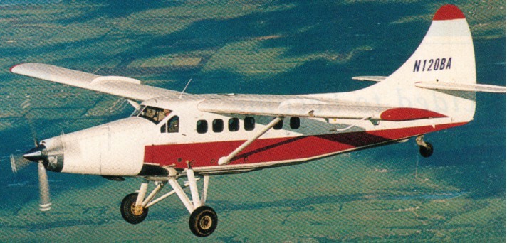
Airplane modifier Texas Turbine Conversions has begun flight testing of its conversion of the de Havilland DHC-3 Otter. The modification includes the replacement of the original 600 hp, nine cylinder Pratt & Whitney radial with an AlliedSignal/Garrett TPE331 10 turboprop engine flat rated to 900 horsepower. While the airframe is limited to a 125 knot airspeed, the additional power helps the Otter climb better and fly at max speeds to much higher altitudes than it could with the radial. The engine swap saves 400 pounds, which translates into a better useful load, and gives operators a greatly increased TBO up to 5,400 hours over the P&W radial.
Ted Smith sold his interest in Aero Commander to Rockwell and by 1966 had completed the first mockup of the Aerostar and production commenced, with finance from American Cement, at Van Nuys. Ted Smith then sold out to the American Cement Company, which, Smith says, simply didn’t know how to run an aircraft business and consequently ran Aerostar into the ground before finally selling out to Butler Aviation, another firm with no experience in manufacture. Butler did nothing with the Aerostar, and eventually, Smith was able to buy back the company and a large inventory of parts at a much lower price than that at which he had sold out in the first place. This sequence of events is crucial; it amounted to a huge gift to Smith, who found himself able to sell a comparatively exotic airplane of excellent performance at unnaturally low prices, because he obtained his parts – enough of them to make hundreds of airplanes in some cases at a huge discount. Thus, after only a short time in business, Smith could boast of a 10 percent annual return (before taxes), one of the highest in the industry.
Designed by Ted Smith during late 1964 as a dual controlled high performance twin engined executive / light transport aircraft, the prototype N540TS first flew in November 1966 and had 160 horsepower Lycoming IO-320 engines, but the airframe was designed to take various powerplants up to turbines without major changes. Accommodating six passengers, the cabin measures 12 ft 6 in long, 46 in wide, and 48 in high and a 30 cu.ft baggage compartment aft has an external access through a 24in high and 22in wide door.
Entry through the left hand clamshell door allows everyone to board before the pilot, get settled in, and then he just slides in and buttons up. Also situated on the port side is the door to the 30 cu ft 240 lbs baggage locker. The two 24 volt batteries are situated in the rear fuselage area along with the 35,000 BTU heater. Large fowIer flaps are fitted and, like the undercarriage, are hydraulically operated. The main undercarriage wheels retract inwards while the nose wheel retracts forwards. The undercarriage is held in the up position by hydraulic pressure alone, there is no lock.
Aerostar 600
The Aerostar 600 received FAA certification (TC A17WE) during March 1968 for the Ted Smith Aircraft Co. The production type flying for the first time during October 1967. The 290 hp Lycoming IO 540, used on the first production airplane delivered in 1968, was available on Aerostars in a normally aspirated or a turbocharged version. The FAA approved the type on 12 April 1978 for Piper.
Aerostar 600A
The prototype first flew in 1966 and had 180 horsepower engines, but the airframe was designed to take various powerplants up to turbines without major changes. The 290hp Lycoming IO 540, used on the first production airplane delivered in 1968, was available on Aerostars in a normally aspirated or a turbocharged version.
The three Piper Aerostars the non turbocharged 600, turbocharged 601 B and pressurized 601P are virtually identical in appearance. Heavy, butt joined and flush riveted skins give the airplane an extremely smooth surface, and the thicker than usual gauge metal serves two purposes. Its extra strength reduces the amount of internal structure needed, and it deforms less during flight to more accurately retain its aerodynamic shape.
Aerostars all have power steering. The nosewheel is turned by pressing the left or right side of a spring loaded rocker switch on the center console. The switch actuates a solenoid that directs hy¬draulic system pressure to a combination shimmy damp¬er/steering cylinder on the nosewheel. The controls are connected by push pull rods. The right engine on the Aerostar has the only hydraulic pump, which supplies pressure for the gear, flaps and power steering. To retract the gear after a right engine failure, the propeller must be allowed to windmill for eight seconds to provide sufficient hydraulic pressure. An extended gear subtracts 300 fpm from the rate of climb. A single engine go around with the right engine dead would be extremely difficult. The optional electric hydraulic backup pump would seem a desirable investment.
There are no up-locks on the gear. It is held in the retracted position by hydraulic pressure and by a pressure accumulator should the pump fail.
Smith designed the fuel system to be as simple as possible. There is a 42 USgallon fuselage tank behind the cabin and a wet wing cell on each side extending from the engine nacelle to the wingtip. Because of the thin, laminar flow wing, these tanks are long and shallow. They each hold 66.25 USgallons usable, for a total usable capacity of 174.5 USG. The fuel gauge displays the total capacity of the three tanks; by moving a spring loaded toggle switch, you can read the capacity of either wing tank. To obtain the quantity of the center tank, you must subtract the amount in each wing tank from the total readout.
The electrically operated fuel valves (one for each engine) have three positions – on, off and crossfeed. With the selectors “on,” each engine draws from both the center tank and its own wing tank. The system is arranged so that the wing tanks will run out first, leaving the center tank to feed the remaining fuel to both engines. The intent was that for normal operations the pilot would select ‘on,’ and forget about fuel management.
The Aerostar has standard leather upholstery covering bucket seats. Most used 600s and 601s have a brake mod which apparently remedied a pad deficiency in the original system. The fuselage: four longerons, widely spaced frames, heavy skins, butt joints, all rivets machine-countersunk and shaved, wide open spaces of unsupported panel. In a departure from classical design practice, Smith designed his structures with skins one or two gauges thicker than are commonly used, and with fewer than the usual number of frames and longerons. Stringers—stiffeners riveted across wide sheet panels to prevent buckling—are omitted entirely. Smith’s rationale was that some of the added skin weight would be made up by eliminating many detail parts; and that thick skins could be depended on to provide strength in compression, while thin ones could not. Thick skins would make the wing stiff enough to be free of flutter at jet speeds, despite a laminar airfoil thin enough to have a fairly high critical mach number. The tail feathers are interchangeable. All the control surfaces are moved by push-pull tubes; there is no aileron trim— fuel is crossfed to correct wing heaviness—and yaw and pitch trim are electric, with gearhead motors providing part of the control surface balance. Mammoth fittings and pins in quadruple shear connect the wing box to the fuselage at four points. The wing box passes through the fuselage just behind the last pair of seats; above it is a large hat shelf, and behind it a fuel tank. Still farther aft in the fuselage is the luggage compartment, situated at shoulder level. The entire cabin is ahead of the wing spar. The wing loading is high—32.4 lb/sq ft at gross in the normally aspirated Model 600, whose gross weight is 5500 pounds. The fuel system is controlled by motor-driven electric valves which take their cues from three-position rotary switches on the panel: Off, On, Crossfeed. Normally, each engine feeds from,its wing and the fuselage tank; on crossfeed, it would feed from the opposite wing tank only. Fuel is taken in through three fillers, one in the fuselage and two at the wing tips (the entire wing outboard of the engine nacelles is wet), and all three sumps are drained at a convenient point on the underside of the tail cone. All hydraulic pressure, in the standard version of the system, is provided by a pump on the right engine. A small accumulator in the tail cone provides standby power in emergencies. Hydraulic power is used for the gear, flaps, and nosewheel steering. The nosewheel steering system consists of a rocker switch on a center subpanel (which also has the trim switches) which directs a restricted flow of hydraulic fluid to either side of the shimmy dampener, depending which way you want to turn. Holding the rocker switch down feeds fluid to the appropriate side, turning the nosewheel in proportion to the time the switch is held de¬pressed. Since it is the nature of a shimmy dampener to permit controlled leakage from one side of the piston to the other, the nosewheel tends to center itself gradually once deflected. A steering failure is there¬fore not critical; the airplane can be steered with brakes.
The 601A became the B model in 1977 with the addition of 15 inches to each wingtip for increased stability at high altitudes, automatic rather than manual wastegate controls and a 300 pound gross weight increase. The 1978 model has an improved wastegate that is more durable and efficient, resulting in an increase of critical altitude from 16,000 to 23,000 feet.
The first 601P rolled off the production line in May 1974, as a 1975 model. The first 601P had “short” wings, with a span of just over 34 feet. The factory extended the wings early in the production run and virtually all of the airplanes built with less span were redone by the factory to the new 36.67 foot wingspan. Maximum cruise on the first 601P was shown in the pilot’s operating hand book as 256 knots at 25,000 feet.
By 1970 the plant was too small, and through lack of capital, the Aerostar type certificate was sold to Bulter Aviation. Production was carried out for them by Mooney as ” Mooney Aerostars”. On 7 December 1972, Ted Smith & Associates was formed with Butler Aviation to continue Aerostar production, which by 1975 it was in full product¬ion in California in three versions, the normal 600 series, the turbo-charged 601 and the pressurised 601P, and remained until the death of Ted Smith and subsequent sale of all rights to Piper, on 27 March 1978.
The Aerostar 601P, Lycoming IO 540 SIA5, 290 hp each, was priced at $220,900 (1977). The 1978 optional blower in the ventilation system helps to keep the cabin bearable on the ground.
Piper Aircraft adopted the name Sequoya for a production version of what was the Smith Aerostar. The specification of the PA 60 Sequoya 602P is almost identical with that of the Aerostar 601P, but a change of engine variant achieves a greater range at a reduced cruising speed, a better rate of climb on one or two engines, a better service ceiling and improved take off performance.
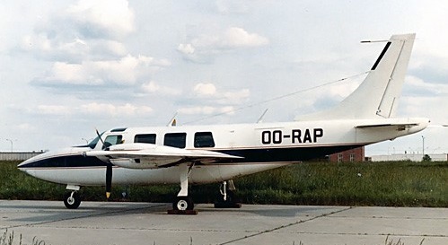
Piper Aerostar PA60-600 OO-RAP (c/n 61-0273-105)
In 1981, Piper introduced the 602P. This airplane is virtually identical to the 601P except for the engines, and they are quite different, even though the horsepower remains the same at 290 a side. The 602P has an engine turbocharger package that was designed as one unit and offers greater usable horsepower. This can be seen directly in single engine ceiling: 12,900 feet compared with 9,300 feet for the 601P. Maximum cruise was scaled back a bit from the 601P’s original number, to 245 knots. Some of this l l knot loss can be attributed to a higher maximum takeoff weight, 6,000 pounds as compared with 5,700 pounds for the original, and the rest would go to the drag of the extended wingspan.
To get more from the airplane, Piper installed more horsepower for the 700P. The basic Lycoming 540-cubic-inch-displacement engines run at higher turbo boost, developing the additional 60 hp per side. Lycoming has retained the same 1,800-hour recommended TBO. Each engine uses two turbochargers. The 700P engines counterrotate, rotate opposite the direction of other twins’; on the 700P, the prop tips rotate away from the top of the fuselage. This came from a retest of the Aerostar design that mandated an improvement in directional control when flying at low airspeeds. The directional control problem was addressed on other models by adding vortex generators, or a supplemental ventral rudder under the tailcone. The 700P also became the first Aerostar produced with cowl flaps and with intercoolers.
The 700Ps cruise number is 261 knots at 81 percent power and 25,000 feet, so, even with the extra pow¬er, not a lot of speed is gained over the 601P. Because the 700P uses fuel at 307 pph at 81 percent pow¬er, an optional additional 40 USG fuel tank was made available, and most were equipped with it, increasing maximum fuel load to 1,233 pounds, enough for a five-hour flight at relatively high power. With the extra tank, this gave a total of 1,233 pounds (205.5USG). Only 25 or these were built.
The 700 Superstar was the prototype of a stretched fuselage variant. With additional fuel capacity and increased take-off weight, registered N72TS, it first flew on 22 November 1972.
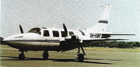
The Speedstar 850 was a modification to fit one nose mounted turboprop engine, instead of the two wing mounted engines. 25 were produced between 1983 and 1985.
Speedstar 850
The Aerostar was produced between 1967 and 1984, of the 1010 produced, 519 were built by Piper.
Aerostar 600 Engines: 2 x Lycoming IO-540, 290 hp Wing Span: 34 ft 2.5 in / 10.43 m Length: 34 ft 9.75 in / 10.61 m Height: 12 ft 1.5 in Wing Area: 170 sq ft Wing Loading: 32.3 lb/sq ft Power Loading: 9.5 lb/sq ft Baggage Capacity: 30 Cu ft, 200 lb MTOW: 5,500 lb / 2495 kg Max Zero-Fuel Weight: 4,450 lb Empty Weight: 3425 lb / 1553 kg Standard Useful: 1,700 lb Minimum Control Speed: 97 mph Best Rate of Climb Speed: 145 mph Best Rate of Climb Single Engine: 135 mph Best Angle of Climb Speed: 125 mph Best Angle of Climb Single Engine 125 mph Never Exceed Speed: 278 mph Maneuvering Speed: 187 mph Max Flap Extension Speed: 20 degrees – 180 mph, Full flaps: 148 mph Max Gear Extension Speed: 180 mph Max Gear Retraction Speed: 150 mph Max Speed at Sea Level: 260 mph Cruising Speed 70% at 10,000 ft / 3050m: 250 mph / 217 kt / 402 kph Cruising Speed 65% at 10,000 ft: 209 kts Cruising Speed 55% at 10,000 ft: 223 mph Stalling Speed: (dirty, power off) 77 mph Rate of Climb at Sea Level: 1,850 fpm / 564 m/min Rate of Climb Single Engine: 450 fpm Service Ceiling: 22,000 ft Single Engine ceiling: 6,300 ft Takeoff Distance: 1,095 ft Takeoff Distance Over 50ft: 2,120 ft Landing Distance: 932 ft Landing Distance Over 50 ft: 2,032 ft Fuel Capacity (usable): 170 USG Range (max fuel, 45 min res) max cruise, 250 mph: 1,063 sm Range (max fuel, 30 min res) 65% 10,000ft/3050m, 250 mph: 1,400 sm / 1216 nm / 2250 km Max range, 204 mph: 1,650 sm Wheel track: 10.2 ft Baggage cap: 240 lbs / 109 kg / 30 cu.ft / 0.85 cu.m Seats: 6 Vmc: 92 mph T/O dist: 1000 ft T/O dist 50 ft: 1400 ft Ldg dist: 895 ft Ldg dist 50 ft: 2420 ft Cabin length: 12 ft 6 in / 3.81 m Cabin width: 3 ft 10 in / 1.17 m Cabin height: 4 ft 0 in / 1.22 m
Aerostar 600A
similar to the 600 but with minor detail changes. Engines: 2 x Lycoming IO-540-K1J5, 290 hp TBO: 2000 hrs Props: Hartzell 3-blade CS full feathering 6 ft 6 in Wingspan: 34 ft 2 in Wing area: 170 sq.ft Wing aspect ratio: 6.9 Length: 34 ft 9.75 in Height: 12 ft 1.25 in Max ramp wt: 5525 lb Max take off wt: 5500 lb Standard empty wt: 3560 lb Max useful load: 1763 lb Max landing wt: 5500 lb Wing loading: 32.4 lbs/sq.ft Power loading: 9.5 lbs/hp Max useable fuel: 993 lb / 177 USG Baggage capacity: 240 lb Climb rate: 1800 fpm @ 122 kt Climb gradient: 885 ft/nm Rate of climb @ 8000 ft: 1150 fpm Service ceiling; 21,200 ft SE rate of climb: 360 fpm @ 113 kt SE climb gradient: 239 f/nm SE ceiling: 6300 ft Max speed SL: 260 mph / 226 kt Cruise @ 65% power @ 8,000ft: 207 kt Fuel flow @ 65% power @ 8,000ft: 185 pph Endurance @ 65% power @ 8,000ft: 5.1 hr Cruise speed 10,000ft: 250 mph Stalling speed clean: 76 kt Stall speed gear/flaps down: 74 kt Turbulent air penetration speed: 163 kt Retractable undercarriage T/O dist (50 ft): 1400 ft Ldg dist (50ft): 1950 ft Range 9000ft: 1408 mi Seats: 6
Aerostar 600AE Designation for types sold in Europe
Aerostar 601 / PA-61 Later designated PA-61 FAA approved during November 1968 for the Ted Smith Aircraft Co and on 12 April 1978 for Piper. Engines: 2 x Lycoming IO-540-S1A5, 29 hp Ceiling: 20,000 ft Max speed: 240 kts Fuel cap: 177 USG Range (no res): 1436 sm Stall, clean: 77 kts Vmc: 80 kt 117 produced.
Aerostar 601B / PA-61 Later designated PA-61 Increased wingspan, same as 601P Engines: 2 x Lycoming IO 540 P1A5 or S1A5, 290 hp TBO: 1,800 hrs Props: Hartzell constant speed, full feathering Wingspan: 36 ft 8 in Length: 34 ft 9.75 in Height: 12 ft 1.25 in Wing area: 178.2 sq.ft Baggage capacity: 240 lb Empty weight: 4031 lb Useful load: 1,969 lb Payload with full fuel: 922 lb Gross weight: 6,000 lb Maximum landing weight: 6,000 lb Usable fuel capacity: 174.5 USG/1,047 lb Wing loading: 33.6 lb/sq.ft Power loading: 9.13 lb/hp Max speed 25,000ft: 302 mph / 259 kt Max cruise, 75% power at 25,000 ft: 236 kt Econ cruise, 55% power at 25,000 ft: 212 kt Duration at max cruise: 4.8 hr Duration at econ cruise: 6.4 hr Stalling speed, clean: 79 kt Stalling speed, full flaps: 71 kt Maximum rate of climb: 1,530 fpm Single engine rate of climb: 254 fpm Single engine climb gradient 109 knots (Vyse): 141 ft/nm Certificated ceiling: 30,000 ft Single engine service ceiling: 9,250 ft Takeoff 50 ft: 2310 ft Landing from 50 ft: 2175 ft Range 25,000ft: 1435 mi Seats: 6 44 produced
Aerostar 600BE Designation for types sold in Europe
Aerostar 600P / PA-61P Later PA-61P. Produced from 1972, pressurised, increased weights and turbocharged engines. 492 produced
Aerostar 600PE Designation for types sold in Europe
Aerostar 601P Engine: 2 x Lycoming IO-540-S1A5, 290 hp Seats: 6 Wing loading: 33.7 lb/sq.ft Pwr loading: 10.2 lb/hp Gross wt: 6000 lb Empty wt: 4000 lb Equipped useful load: 1970 lb Baggage capacity: 240 lb Payload max fuel: 923 lb Range max fuel/75%: 1125nm/4.5hr Range max fuel /55%: 1304nm/6.2hr Service ceiling: 26,350 ft Max speed 25,000ft: 290 mph 75% cruise @ 25,000 ft: 247 kt Cruise: 230 kts @ 65% pwr @ 20,000ft 55% Cruise: 212 kt Vmc: 80 kt Stall: 69-77 kt 1.3 Vso: 90 kt ROC: 1530 fpm SE ROC: 285 fpm @ 117 kt SE ceiling: 9100 ft Min field length: 2047 ft T/O dist (50 ft): 2310 ft Ldg dist (50ft): 2100 ft Fuel cap: 1047 lb / 177 USG Cabin pressure: 4.25 psi
PA-60 Aerostar 602 Engines: 2 x 290 hp Lycoming Seats: 6 Empty Wt: 4125 lbs Gross wt: 6000 lbs Useful load: 1875 lbs Max Cruise: 283 mph Max range: 1260 sm
PA-60 Aerostar 602P Piper-developed version of the 601P with the 290 hp Lycoming TIO-540-AA1A5 engines First built: 1974 Engine: 2 x Lycoming IO-540-AA1A5, 290 hp TBO: 1800 hr Prop: Hartzell 3 blade, constant speed 78 in Seats: 6 Length: 34.8 ft Height: 12.1 ft Wingspan: 36.7 ft Wing area: 178 sq.ft Wing aspect ratio: 7.6 Max ramp wt: 6029 lb Max take off wt: 6000 lb Standard empty wt: 4075 lb Max useful load: 1954 lb Max landing wt: 6000 lb Wing loading: 33.7 lbs/sq.ft Power loading: 10.3 lbs/hp Max useable fuel: 993 lb Climb rate: 1460 fpm @ 117 kt Climb gradient: 749 ft/nm Rate of climb @ 8000 ft: 1320 fpm Certificated ceiling; 25,000 ft 8,000 ft cabin altitude: 20,600 ft SE rate of climb: 240 fpm @ 109 kt SE climb gradient: 131 f/nm SE ceiling: 8800 ft Max speed: 257 kts Cruise @ 65% power @ 8,000ft: 203 kts Cruise @ 65% pwr @ 18,000 ft: 220 kts Fuel flow @ 65% power @ 18,000ft: 182 pph Endurance @ 65% power @ 8,000ft: 5.2 hr Stalling speed clean: 79 kts Stall speed gear/flaps down: 77 kts Turbulent air penetration speed: 167 kts Retractable undercarriage 124 built
1981 Piper Aerostar 602P Engines: 2 x Lycoming IO 540 AA1A5, 290 hp Recommended TBO: 1,800 hrs Props: Hartzell, 3 blade, 78 in dia Length: 34.83 ft Height: 12.17 ft Wingspan: 36.67 ft Wing area: 178 sq ft Max ramp weight: 6,029 lbs Max takeoff weight: 6000 lb Empty weight: 4,406 lb Useful load: 1,623 lb Zero fuel weight: 5,900 lb Maximum landing weight: 6,000 lb Wing loading: 33.7 lbs/sq ft Power loading: 10.3 lbs/hp Max usable fuel: 165.5 USG/993 lb Certified ceiling: 25,000 ft Max pressurization differential: 4.25 psi 8000 ft cabin altitude at: 20,600 ft Max rate of climb: 1,755 fpm Max single engine rate of climb: 302 fpm Single engine climb gradient: 154 ft/nm Single engine service ceiling: 12,900 ft Maximum cruise speed, FL 250: 245 kt Cruise, 65% power at 15,000 ft: 210 kt Cruise, 65% power at FL 250: 226 kt Fuel flow at 65%: 32.4 gph, 199.4 pph Endurance at 65%, no res: 6.2 hr Stalling speed, clean: 86 kts Stalling speed, flaps down: 77 kt Turbulent air penetration speed: 167 kt
620 A pressurised Aerostar with 310 hp TIO-540 engines, one built.
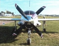
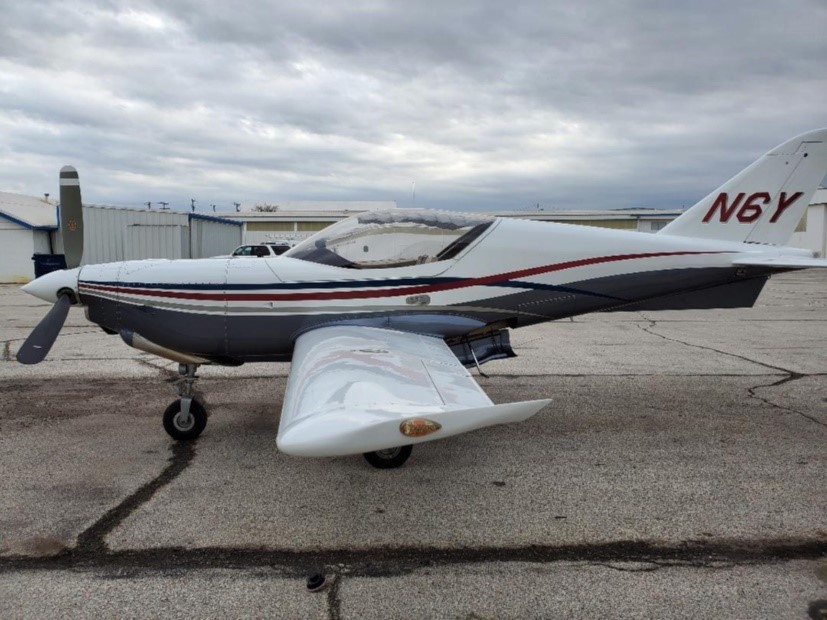
The prototype (N6Y) of this compact trainer design made its first flight at San Antonio, Texas, on 31 May 1989. Powered by a 420 shp (313 kW) Allison 250-B17D turbo-prop, the SA-32T has been developed by Swearingen in conjunction with Jaffe Aircraft Corp. Despite its relatively small size, the SA-32T incorporates a retractable undercarriage, a limited amount of composite material in the airframe and a NASA-designed laminar-flow wing. Jaffe Aircraft abandoned the program.
N6Y is still flying. Purchased from Jaffe in 2002. My wingtip design lower the full-flaps stall to 68 kts. Trues out a 280 kts. William B Acheff, April 2020
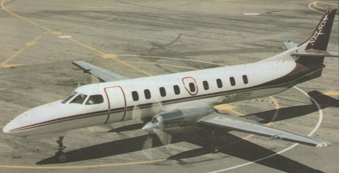
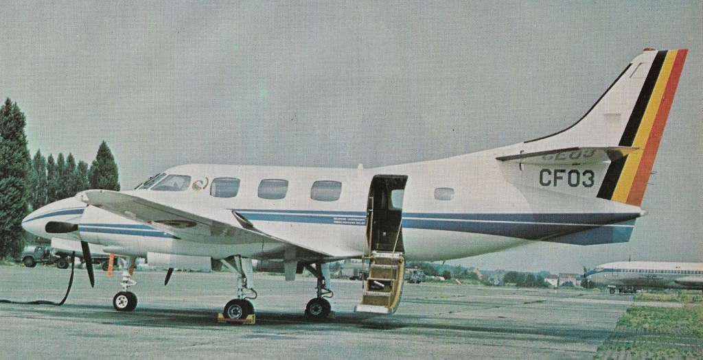
The evolution of the Merlin started in the early 1960s, with an air stair door and engine conversion for the Beech Twin Bonanza. Swearingen was also fitting bigger engines on Queen Airs, and the first Merlin strongly reflects his background with these two Beech conversions. The Merlins I and II consisted of a new fuselage mounted on modified Queen Air or Twin Bonanza wings and landing gear. The Merlin I was to be a pressurized piston powered airplane, the Merlin II a turboprop. The model I was never produced because Swearingen couldn’t find a piston engine that satisfied him. The II made its debut with Pratt & Whitney PT6 turboprops in 1969, but by the time it reached the IIB version, it was powered by Garrett AiResearch TPE 331s with a shaft horsepower of 665 each, and it had a takeoff weight of 10,000 pounds.
The next step had to be the development of a new wing. There just weren’t that many Twin Bonanzas and Queen Airs out there, waiting to donate their wings to a Merlin. There may also have been some reluctance on the part of prospective buyers to consider a new airplane with used wings. Thus came the Merlins III and IV.
Dramatically improved performance, extended payload-range capability and a host of safety features transformed the Metro II into the Metro III. Providing the the improved performance is a 10 foot extension to the earlier model’s wing, combined with an uprating of the twin Garrett AiResearch TPE turbo-props from 840 SHP to 1,100 SHP. Water methanol injection is standard for hot and high take-offs, as well as being available for power augmentation during normal take-offs. Rated at 1,100 SHP wet, 1,000 SHP dry, power is now absorbed by new four-bladed Dowty Rotol props. Turning at 1,590 rpm (compared with 2,000 rpm on the Metro II), the interior noise level has been dramatically reduced to about half that of the previous model about a 6 Db drop.
Fairchild was building the Merlin’s wings under contract to Swearingen when the recession of 1970 squeezed the airplane business. Fairchild wound up with both an interest in the company and an in¬terest in keeping the airplanes going. The Merlin III was under development at about the time the small jets were first coming to market; to be a viable offering, it had to offer something the jets lacked. This had to be range, for there was no way a turboprop could match the jets’ speed. The first Merlin III had AiResearch 840 shp engines and a fuel capacity of 662 USG. The maximum range at economy cruise, with a 45 minute reserve, was 2,353 nautical.
Other changes to the Metro II include a cleaning up of the engine nacelle and improved fire containment. The gear doors now close when the wheels are lowered, which not only improves the single-engine gear-down performance, but also assists in lowering the Vmca to 5 knots slower than the series II aircraft. Cowlings are stainless steel for improved fire resistance, while all flammable fluid lines are physically isolated from electrical componentry and wiring. Fire extinguishers are located in each engine nacelle.
In all there are some 1070 major engineering changes over the Metro II, mainly covering safety related items, and this effectively ups the new aircraft’s empty weight by about 550 lbs.
The Metro III is certified to 14,000 pounds (6,350 Kg.) MAUW, with a 12,500 lb zero fuel weight. Approved by both F.A.A. under new SFAR 41 and by ICAO Annex 8.
Swearingen Merlin IIIA
The Merlin IIIB has 900 shp Garrett AiResearch TPE 331-10U-501G engines, four blade instead of three blade props, and an extra gear in the reduction system that limits the prop to 1,591 rpm and makes the props turn to the left. Prop rpm for the III was 2,000, so this is a significant reduction.
Certification of the IIIB by the FAA was confirmed on 3 November and the first production example was delivered to Teterboro Aircraft Services on 1 December.
The Merlin IIIB is normally flown in the 25,000 to 28,000 foot range. At gross weight, it takes 17 or 18 minutes to reach 26,000 feet. Flight Level 260 is close to where the maximum range and maximum speed lines meet on the chart. The speed up there at 12,000 pounds is 269 knots at .52 nautical miles per pound of fuel burned, for a flow of about 530 pounds an hour. At 10,000 pounds, a more common mid cruise weight, the specific range can be as high as .6 nautical miles per pound of fuel consumed, with a cruise speed still over 260 knots, at 30,000 or 31,000 feet.
The Merlin IIIB is a purpose-built, high capability executive aircraft. Powered by a brace of 900 s.h.p. Garrett Ai-Research turboprops, the IIIB can wind out to a 300 knot cruise, carry eight passengers and crew of two for over a thousand miles. (Initial rate of climb at gross is 2,782 fpm, while over a thousand feet per minute can be averaged right on through to the service ceiling of 31,000 feet.) Single engine rate of climb at gross is 700 fpm; service ceiling with one out 16,500 feet. The Metro III also exists in an all-cargo configuration, known as the Expediter, with changes which permit payloads of 5,000 lb (2 268 kg). Fairchild, by 1990, had begun delivery of 13 C-26A versions to the US ANG.
The Merlin III is like the VI, only shorter, lighter and faster. It has a six passen¬ger cabin with a slide out potty in the rear. An equipped III will weigh, 7,200 to 7,300 pounds empty, 12,500 at gross. It has a maximum cruise speed of 275 knots, nine knots faster than the IV. Both aircraft have a 12,560 pound ramp weight and a landing weight of 11,500 pounds.
The primary difference in the two airplanes is range. The IV will carry crew, three passengers and baggage 1,875 nm at 226 knots, or at high cruise it will take the three 1,390 nm at 265 knots. The III will carry three passengers 2,255 nm at 257 knots in economy cruise, or 1,610 nm at 275 knots in high cruise.
Sharing the same wing and fuselage section with that of its big brother the Metroliner, the 17 foot shorter Merlin fuselage is pressurised to 7 psi differential, allowing cabin pressure to remain at sea level during a 17,000 foot cruise, or a 7,300 foot cabin at 31,000 feet. Going hand in hand with the capable pressurisation system, interior sound levels too have been designed with comfort in mind. Big slow turning four-bladed props, coupled with increased sound-proofing over earlier models, results in remarkably low cabin noise levels — similar in fact to a jet, and with a silky, vibration-free smoothness in flight that would hardly ruffle the surface of the boss’s gin and tonic. Elbow room in the cabin too is excellent. Maximum cabin width is a generous 5.2 feet; headroom is 4.8 feet.
Range and payload combinations are flexible. With a crew of two and virtually no payload, range is better than 2,000 miles (this with 4,342 pounds of fuel total), while with a full payload of 1,770 pounds on board the Merlin achieves 1,100 miles at 288 knots, still retaining a 45 minute reserve. Fuel flow shows around 600 pph.
Fully reversing prop blades and powered anti-skid braking assist with the field performance. Low pressure tyres are fitted and the Garretts can be equipped with water-methanol injection as an optional extra.
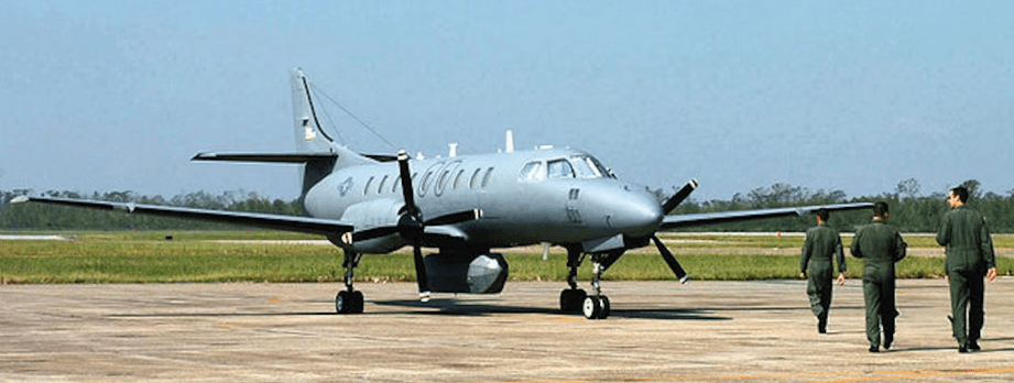
Developed from the Metro II, the Metro III version is operated by several air forces as a utility transport. The US Air National Guard designates its variant the C-26A. Other models are the Metro III(H) with a 16,000-lb (7,258-kg) maximum take-off weight (ANG C-26B), and the Expediter all-freight model with a 4,780-lb (2,168-kg) payload.
For specialized military roles, the manufacturer provides the Metro III Special Missions Version – A Special Missions aircraft based on the Metro III airframe is available for various maritime patrol/surveillance and ASW duties. Mission equipment includes a Litton 360 deg scan APS-504(V) or AIL APS-128D search radar in an underfuselage radome for maritime surveillance, and a sonobuoy acoustic processor and a MAD tailboom for the ASW role. Optional equipment in both cases comprises low-light TV, infrared linescanner, Flir, Doppler radar, and a searchlight. Maximum take-off weight is 7,257kg (16,000lb), and endurance with auxiliary fuel tanks is ten hours. Also operated by the Swedish Air Force as Tp 88s.
The Merlin IV has the same basic airframe/engine combination as the Swearingen Metro commuter airliner, but there the similarity ends. The IV systems are so different from the Metro, and the capabilities of the airplanes are so distinct, that the two have separate type certificates.
The IV is a 10 passenger airplane in standard corporate configuration. It weighs 12,500 pounds maximum for takeoff and cruises at 265 knots. The design has what engineers sometimes call “maximum mission capability”: that is, with full tanks, full avionics and miscellaneous equipment, it will accommodate only the crew for maximum range ferry purposes. From this condition you trade off range for payload to a maximum of 2,800 2,900 pounds in passengers and baggage and 1,500 pounds of fuel.
Behind the rear cabin bulkhead is a pressurized, 136 cubic foot, 500 pound limit baggage/cargo compartment accessible through a 53 inch wide door on the left side of the fuselage. A second, un-pressurized, 45 cubic foot baggage compartment in the nose will hold up to 800 pounds, less the weight of avionics boxes. Cabin pressure differential is seven psi, which gives the IV a sea level cabin at 16,000 feet, its maximum cruise speed altitude. There are dual pressurization, heat and air conditioner systems.
The Swearingen Aviation Corporation, a subsidiary of Fairchild Industries, added 17 feet to the length of an executive turboprop fuselage to create an airplane for both airlines and corporate operators. The 1976 models of the long Swearingen were called the Merlin IVA and the Metro II. The former is a corporate airplane, the latter is used for airline operations. The Merlin and Metro 4 are air conditioned and pressurized. When it is used as an executive transport, the Merlin’s passenger load is usually lower and larger fuel loads can handle much longer trips with the average executive load. When cargo carrying missions are combined with passenger operations, a Metro II “Expediter” version of the airplane is available. Its movable bulkheads and removable interiors facilitate a quick change from passenger to cargo operations or to any mixture of the two. The Swearingen Metro II and Merlin IVA received a restricted category certification that will permit them to operate at gross weights of up to 14,000 pounds. Special mission editions of the turboprops, designed for patrols or aerial photography, are able to carry 648 gallons of fuel, for up to 10 hours of endurance.
Fairchild’s SA 227-DC Metro 25 flew for the first time on 25 September 1989.
The Fairchild RC-26 offered an aerial surveillance option for local and federal law enforcement agencies, allowing them to cut down on high-speed chases and more easily gather evidence on drug trafficking organizations. During the eight-year span of operations, the RC-26 flying flew over 4000 hours contributing the seizure of one billion dollars’ worth of narcotics and leading to over one thousand arrests.
RC-26
In addition to supporting counter-narcotics operations, the RC-26 crew supported emergency management agencies during natural disasters including forest fires on the west coast, flooding in the Midwest and hurricane Maria in Puerto Rico. The aircraft provided vital imagery of affected areas to emergency crews on the ground.
Fairchild Metro III two/three-crew light transport Engines: two l,000-shp (746-kW) Garrett TPE33I-l1U-611G turboprops Maximum speed 320 mph (515 km/h) at 12,500 ft (3,810 m) Initial climb rate 2,350 ft (716 m) per minute Service ceiling 27,500 ft (8,380 m) Range 1,000 miles (1,609 km) with maximum passenger payload Empty weight 8,737 lb (3,963 kg) Maximum take-off 14,500 lb (6,577 kg) Wing span 57 ft 10 in (17.37 m) Length 59 ft 4.25 in (18.09 m) Height 16 ft 8 in (5.08 m) Wing area 309.0 sq ft (28.71 sq.m) Payload: 20 passengers or 4,880 lb (2,214 kg) of freight
Metro IIIA Engines: Garrett, 840 shp TBO: 2500 hr Max cruise: 278 mph Econ cruise: 244 mph Stall: 83 mph Fuel cap: 4342 lb Service ceiling: 28,900 ft SE service ceiling: 15,000 ft ROC: 2530 fpm SE ROC: 620 fpm Min field length: 2150 ft Payload with full fuel: 389 lb Max range: 2487 sm High speed range: 1953 sm Max payload: 2060 lb Range with max payload: 1154 sm Pressurisation diff: 7.0 psi Seats: 11 Gross wt: 12,500 lb Equipped empty wt: 7769 lb Useful load: 4731 lb
SA227-AC Metro III-41 Engines: 2 x Garrett TPE-331-IIU-601G, 1000 shp Props: Dowty-Rotol 4-blade, 106-in Seats: 22 Length: 59.4 ft Height: 16.7 ft Wingspan: 57 ft Wing area: 309 sq.ft Wing aspect ratio: 10.5 Maximum ramp weight: 14,100 lb Maximum takeoff weight: 14,000 lb Standard empty weight: 8397 lb Maximum useful load: 5703 lb Zero-fuel weight: 12,500 lbs Maximum landing weight: 14,000 lb Wing loading: 45.3 lbs/sq.ft Power loading: 7 lbs/hp Maximum usable fuel: 4342 lb Best rate of climb: 2500 fpm Certificated ceiling: 31,000 ft Max pressurisation differential: 7 psi. 8000 ft cabin alt @: 32,400 ft Maximum single-engine rate of climb: 760 fpm @ 133 kts Single-engine climb gradient: 344 ft/nm Single-engine ceiling: 16,000 ft Maximum speed: 271 kts Normal cruise @ 25,000ft: 264 kts Fuel flow @ normal cruise: 509 pph Endurance at normal cruise: 8 hrs Stalling speed clean: 97 kts Stalling speed gear/flaps down: 87 kts Turbulent-air penetration speed: 174 kts
SA227-AC Metro III-41B Engines: 2 x Garrett TPE-331-IIU-601G, 1000 shp Props: Dowty-Rotol 4-blade, 106-in Seats: 22 Length: 59.4 ft Height: 16.7 ft Wingspan: 57 ft Wing area: 309 sq.ft Wing aspect ratio: 10.5 Maximum ramp weight: 14,100 lb Maximum takeoff weight: 14,000 lb Standard empty weight: 8397 lb Maximum useful load: 5703 lb Zero-fuel weight: 12,500 lb Maximum landing weight: 14,000 lb Wing loading: 45.3 lbs/sq.ft Power loading: 7 lbs/hp Maximum usable fuel: 4342 lb Best rate of climb: 2500 fpm Certificated ceiling: 31,000 ft Max pressurisation differential: 7 psi 8000 ft cabin alt @: 32,400 ft Maximum single-engine rate of climb: 760 fpm @ 133 kts Single-engine climb gradient: 344 ft/nm Single-engine ceiling: 16,000 ft Maximum speed: 271 kts Normal cruise @ 25,000ft: 264 kts Fuel flow @ normal cruise: 509 pph Endurance at normal cruise: 8 hrs Stalling speed clean: 97 kts Stalling speed gear/flaps down: 87 kts Turbulent-air penetration speed: 174 kts
Merlin IIIA Engine: 2 x TPE 331-3U-303G, 840 hp Seats: 11 Length: 42.159 ft / 12.85 m Height: 16.732 ft / 5.1 m Wingspan: 46.26 ft / 14.1 m Wing area: 277.496 sq.ft / 25.78 sq.m Wing loading: 45 lb/sq.ft 220.0 kg/sq.m Pwr loading: 7.44 lb/hp Gross wt: 12,500 lb / 5670.0 kg Empty wt: 7600 lb Equipped useful load: 4531 lb Payload max fuel: 189 lb Range max fuel/cruise: 1720nm/6.3hr Range max fuel / range: 2266nm/9.3hr Ceiling: 31,000 ft Max cruise: 272 kt Max range cruise: 245 kt Vmc: 104 kt Stall: 84-97 kt 1.3 Vso: 109 kt ROC: 2530 fpm SE ROC: 620 fpm @ 143 kt SE ceiling: 13,500 ft Min field length: 3075 ft Take off distance: 3051 ft / 930 m Landing distance: 2854 ft / 870 m Fuel cap: 4342 lb Cabin pressure: 7 psi Crew: 2
Merlin IIIB Engines: 2 x AiResearch TPE 331 1OU 501G, 900 shp Props: Full feathering, reversible, 106 in, dia TBO: 3,000 hrs Length: 42 ft. 1 in Height: 16 ft. 9 in Wingspan: 46 ft. 3 in Wing area: 277.5 sq. ft Max ramp wt: 12,600 lbs Max takeoff wt: 12,500 lbs Standard empty wt: 7,600 lbs Max useful load: 4,900 lbs Max landing wt: 11,500 lbs Zero fuel wt: 10,000 lbs Wing loading: 45 lb/sq.ft Power loading: 6.9 lb/hp Max usable fuel: 648 USG/4,342 lbs Max rate of climb: 2,782 fpm Service ceiling: 31,400 ft Single engine rate of climb: 700 fpm Single engine climb gradient: 304 ft/nm Single engine service ceiling: 16,500 ft Max speed: 309 kts Normal cruise (@ 22,000 ft. and 12,000 lbs.): 280 kts Fuel flow at normal cruise: 600 pph Endurance at normal cruise, no reserve: 7.2 hrs Stalling speed, clean: 103 kts Stalling speed, flaps down: 89 kts Turbulent air penetration speed: 190 kts Max pressurization differential: 7 psi. 8,000 ft. cabin altitude @: 32,400 ft.
Merlin IVA Engines: 2 x Garrett AiResearch TPE 331 3U-303G,840 shp Prop: Hartzell 3 blade,constant speed, full feathering, reversing, 102 in. dia Length: 59 ft. 4 in Height: 16 ft, 8 in Wingspan: 46 ft. 3 in Airfoil: NACA 652A215 at root 642A425 at tip Aspect ratio: 7.71 Wing area: 277.5 sq. ft Wing loading: 45 lbs/sq.ft Empty weight: 8,553 lbs Useful load: 3,947 lbs Payload with full fuel: 235 lbs Ramp weight: 12,560 lbs Maximum takeoff weight: 12,500 lb Power loading: 7.44 lbs./hp Usable fuel capacity: 554 gals/13,712 lbs Baggage area: 143 cu. Ft Minimum runway requirement: 2,050 ft Rate of climb: 2,400 fpm Single engine rate of climb: 650fpm Service ceiling: 27,000 ft Single engine service ceiling: 14,700 ft Maximum cruise (@ 16,000 ft.): 269 knots High altitude cruise (@ 24,000 ft.): 240 knots Maximum range (45 minute reserve): 1,810 nm Stall speed, clean: 97 knots Stall speed, gear and flaps down: 86 knots
SA227-AT Merlin IVC-41 Engines: 2 x Garrett TPE-331-IIU-601G, 1000 shp Props: Dowty-Rotol 4-blade, 106-in Seats: 13/16 Length: 59.4 ft Height: 16.7 ft Wingspan: 57 ft Wing area: 309 sq.ft Wing aspect ratio: 10 Maximum ramp weight: 14,100 lbs Maximum takeoff weight: 14,000 lbs Standard empty weight: 9100 lbs Maximum useful load: 5000 lbs Zero-fuel weight: 12,500 lbs Maximum landing weight: 14,000 lbs Wing loading: 45.3 lbs/sq.ft Power loading: 7 lbs/hp Maximum usable fuel: 4342 lbs Best rate of climb: 2500 fpm Certificated ceiling: 31,000 ft Max pressurisation differential: 7 psi. 8000 ft cabin alt @: 32,400 ft Maximum single-engine rate of climb: 760 fpm @ 133 kts Single-engine climb gradient: 344 ft/nm Single-engine ceiling: 16,000 ft Maximum speed: 297 kts Normal cruise @ 25,000ft: 268 kts Fuel flow @ normal cruise: 527 pph Endurance at normal cruise: 7.7 hrs Stalling speed clean: 97 kts Stalling speed gear/flaps down: 87 kts Turbulent-air penetration speed: 174 kts
SA227-AT Merlin IVC-41B Engines: 2 x Garrett TPE-331-IIU-601G, 1000 shp Props: Dowty-Rotol 4-blade, 106-in Seats: 13/16 Length: 59.4 ft Height: 16.7 ft Wingspan: 57 ft Wing area: 309 sq.ft Wing aspect ratio: 10.5 Maximum ramp weight: 14,100 lbs Maximum takeoff weight: 14,000 lbs Standard empty weight: 9100 lbs Maximum useful load: 5000 lbs Zero-fuel weight: 12,500 lbs Maximum landing weight: 14,000 lbs Wing loading: 45.3 lbs/sq.ft Power loading: 7 lbs/hp Maximum usable fuel: 4342 lbs Best rate of climb: 2500 fpm Certificated ceiling: 31,000 ft Max pressurisation differential: 7 psi. 8000 ft cabin alt @: 32,400 ft Maximum single-engine rate of climb: 760 fpm @ 133 kts Single-engine climb gradient: 344 ft/nm Single-engine ceiling: 16,000 ft Maximum speed: 297 kts Normal cruise @ 25,000ft: 268 kts Fuel flow @ normal cruise: 527 pph Endurance at normal cruise: 7.7 hrs Stalling speed clean: 97 kts Stalling speed gear/flaps down: 87 kts Turbulent-air penetration speed: 174 kts
SA227-TT Merlin IIIC-23 Engines: 2 x Garrett TPE-331-IOU-530G, 900 shp Props: Dowty-Rotol 4-blade, 106-in Seats: 8/11 Length: 42.2 ft Height: 16.8 ft Wingspan: 46.3ft Wing area: 277.5 sq.ft Wing aspect ratio: 7.7 Maximum ramp weight: 12,600 lbs Maximum takeoff weight: 12,500 lbs Standard empty weight: 8090 lbs Maximum useful load: 4510 lbs Zero-fuel weight: 12,500 lbs Maximum landing weight: 12,500 lbs Wing loading: 45.0 lbs/sq.ft Power loading: 7 lbs/hp Maximum usable fuel: 4342 lbs Best rate of climb: 2800 fpm Certificated ceiling: 31,000 ft Max pressurisation differential: 5.5 psi 8000 ft cabin alt @: 32,400 ft Maximum single-engine rate of climb: 780 fpm @ 135 kts Single-engine climb gradient: 346 ft/nm Single-engine ceiling: 16,500 ft Maximum speed: 309 kts Normal cruise @ 25,000ft: 290 kts Fuel flow @ normal cruise: 525 pph Endurance at normal cruise: 7.7 hrs Stalling speed clean: 102 kts Stalling speed gear/flaps down: 89 kts Turbulent-air penetration speed: 189 kts
SA227-DC Metro 23 Engines: 2 x Garrett TPE-331-12 MTOW: 7484 kg
SA227-TT Merlin IIIC-41 Engines: 2 x Garrett TPE-331-IOU-530G, 900 shp Props: Dowty-Rotol 4-blade, 106-in Seats: 8/10 Length: 42.2 ft Height: 16.8 ft Wingspan: 46.3 ft Wing area: 277.5 sq.ft Wing aspect ratio: 7.7 Maximum ramp weight: 13,330 lb Maximum takeoff weight: 13,230 lb Standard empty weight: 8150 lb Maximum useful load: 5180 lb Zero-fuel weight: 12,500 lb Maximum landing weight: 13,230 lb Wing loading: 47.7 lbs/sq.ft Power loading: 7.4 lbs/hp Maximum usable fuel: 4342 lb Best rate of climb: 2650 fpm Certificated ceiling: 31,000 ft Max pressurisation differential: 7 psi 8000 ft cabin alt @: 32,400 ft Maximum single-engine rate of climb: 680 fpm @ 138 kt Single-engine climb gradient: 296 ft/nm Single-engine ceiling: 14,500 ft Maximum speed: 309 kt Normal cruise @ 25,000ft: 290 kt Fuel flow @ normal cruise: 525 pph Endurance at normal cruise: 7.7 hrs Stalling speed clean: 104 kt Stalling speed gear/flaps down: 92 kt Turbulent-air penetration speed: 189 kts
Fairchild (Swearingen) C 26 Metroliner Engines: 2 x TPE 331 11U, 809 shp Length: 59.383 ft / 18.1 m Height: 16.732 ft / 5.1 m Wingspan: 57.087 ft / 17.4 m Wing area: 308.927 sq.ft / 28.70 sq.m Max take off weight: 14502.3 lb / 6577.0 kg Weight empty: 9181.6 lb / 4164.0 kg Max. payload weight: 5300.8 lb / 2404.0 kg Max. speed: 278 kts / 515 km/h Landing speed: 87 kts / 161 km/h Cruising speed: 248 kts / 460 km/h Initial climb rate: 2362.20 ft/min / 12.00 m/s Service ceiling: 27428 ft / 8360 m Wing loading: 46.95 lb/sq.ft / 229.00 kg/sq.m Range: 575 nm / 1065 km Crew: 2 Payload: 20 pax
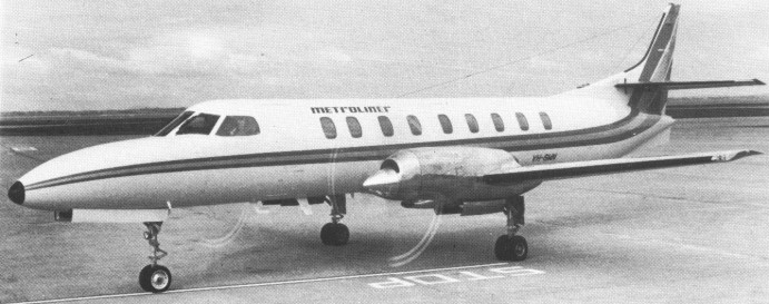
The Metro was developed by Swearingen on the basis of the Beech Queen Air as a commuterliner, and first flew as the SA-226TC 26 August 1969. The first production version was priced at $743,750 in 1974, less avionics. Twenty were built.
Swearingen Metro
The Metro II SA226-TC of 1975 had minor improvements, larger cabin windows.
1969 Metro Engines: two 840hp Garrett AiResearch TPE-331-3UW-303G Wingspan: 46’4″ Length: 59’5″ Useful load: 5125 lb Max speed: 292 mph Cruise: 278 mph Stall: 99 mph Range: 995-2400 mi Ceiling: 27,490′ Seats: 21-22
Metro II SA226-TC Engines: Two Garrett TPE331-3UW-3003G / optional 350 lb Aerojet General JATO Max speed: 294 mph Cruise: 279 mph Stall: 99 mph
SA226-TC Metro II Engines: 2 x Garrett TPE 331 3UW-304G, 840 shp Empty wt: 8150 lb MTOW: 12,500 lb (later 13,100 lb) Pax cap: 20 Cruise: 235 kts @ 15,000 ft, 252 kts @ 10,000 ft Cargo holds: 181 cu.ft Press differential: 7 psi SL cabin alt: 16,000 ft Max op alt: 25,000 ft ROC @ MTOW: 2400 fpm SE ROC: 650 fpm
Engines: Garrett, 940 shp TBO: 2500 hr Max cruise: 283mph Econ cruise: 230 mph Stall: 86 mph Fuel cap: 4342 lb Service ceiling: 27,000 ft SE service ceiling: 14,700 ft ROC: 2400 fpm SE ROC: 650 fpm Min field length: 2050 ft Payload with full fuel: 293 lb Max range: 2110 sm High speed range: 1665 sm Max payload: 4430 lb Range with max payload: 435 sm Pressurisation diff: 7.0 lb. psi Seats: 22 Gross wt: 12500 lb Equipped empty wt: 8219 lb Useful load: 4281 lb
Metro II Engines: 2 x Garrett TPE 331-3UW-303G, 940 hp Seats: 22 Wing loading: 45 lb/sq.ft Pwr loading: 6.65 lb/hp Gross wt: 12,500 lb Operating wt: 7869 lb Equipped useful load: 4500 lb Payload max fuel: 158 lb Zero fuel wt: 12,500 lb Range max fuel/cruise: 1474 nm/5.8 hr Range max fuel / range: 1915 nm/ 7.9 hr Service ceiling: 25,000 ft Max cruise: 255 kt Max range cruise: 244 kt Vmc: 91 kt Stall: 86-98 kt 1.3 Vso: 112 kt ROC: 2400 fpm SE ROC: 650 fpm @ 133 kt SE Service ceiling: 14,000 ft Min field length: 2050 ft Cabin press: 7 psi Fuel cap: 4342 lb
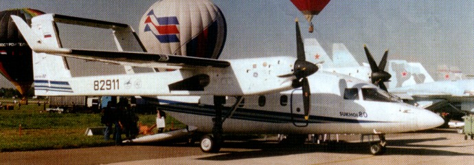
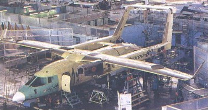
S-80GP Engines: 2 x General Electric CT7-9B turboprops, 1400kW Prop: 4 blade Hamilton Standard 14RF-35 Max take-off weight: 12500 kg / 27558 lb Payload: 3500kg Wingspan: 23.16 m / 76 ft 0 in Length: 16.86 m / 55 ft 4 in Height: 5.58 m / 18 ft 4 in Cruise speed: 535 km/h / 332 mph Ceiling: 6000 m / 19700 ft Range w/max.payload: 700 km / 435 miles Crew: 2
S-80PT Engines: 2 x General Electric CT7-9B turboprops, 1400kW Prop: 4 blade Hamilton Standard 14RF-35 Max take-off weight: 12500 kg / 27558 lb Payload: 3000kg Wingspan: 23.16 m / 76 ft 0 in Length: 16.86 m / 55 ft 4 in Height: 5.58 m / 18 ft 4 in Cruise speed: 535 km/h / 332 mph Ceiling: 6000 m / 19700 ft Range w/max.payload: 700 km / 435 miles Crew: 2