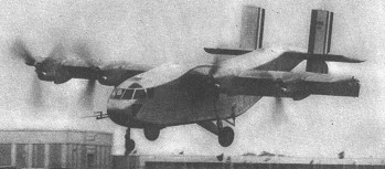
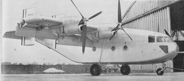
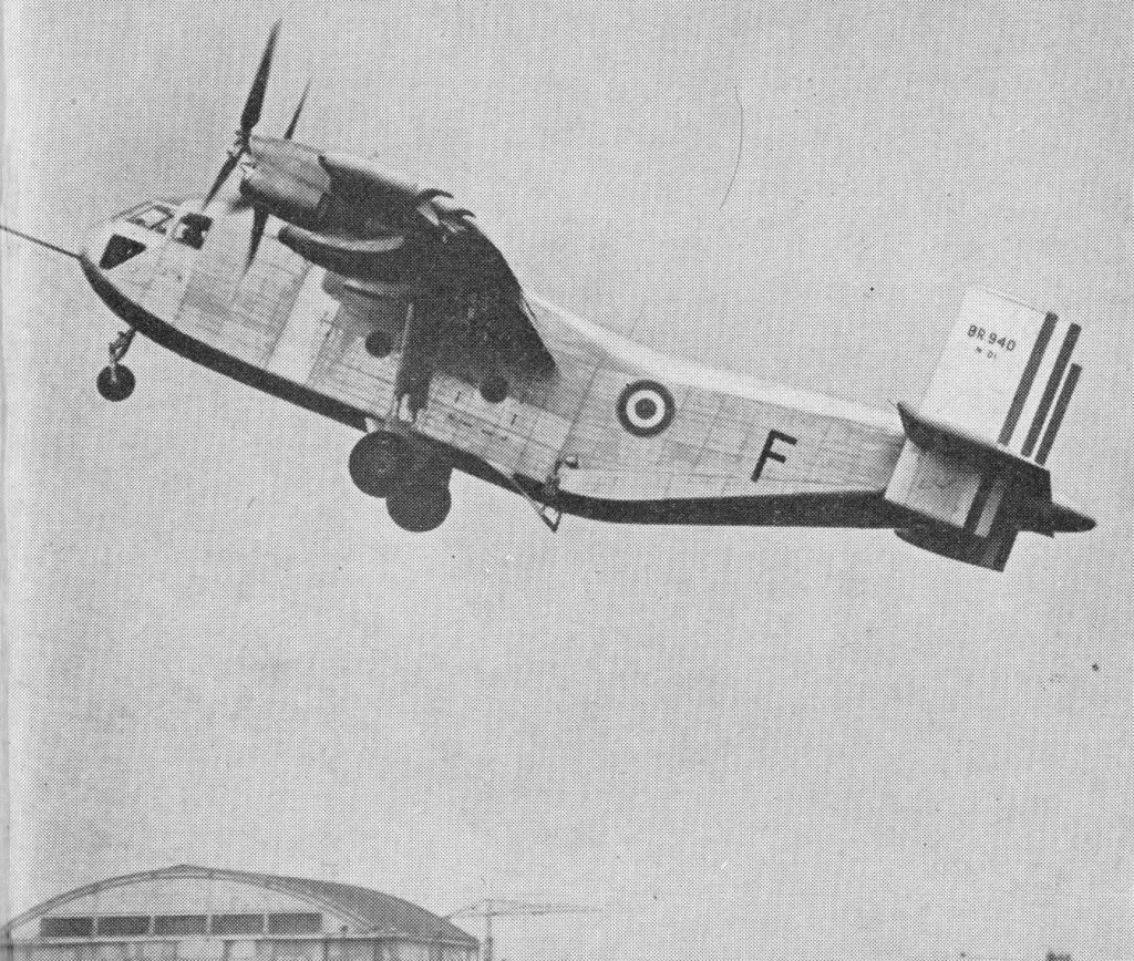
The experimental Bregeut Br.940 first flew on 21 May 1958. For STOL operations, it is fitted with camber-changing slotted flaps, and large diameter, slow turning propellers driven by Turbomeca Turmo II turboprops.
The Br.940 was the prototype for the Br.941 series production.
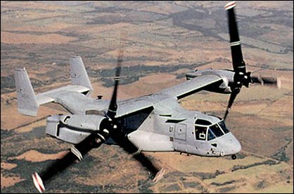
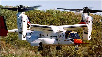
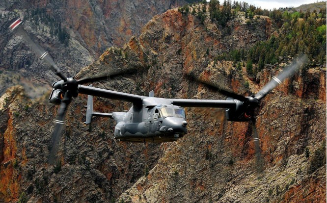
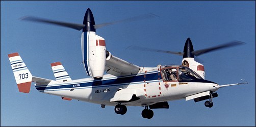
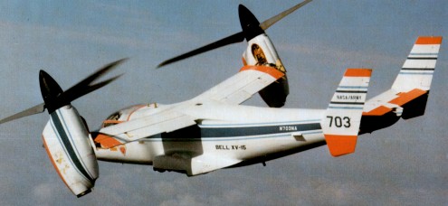
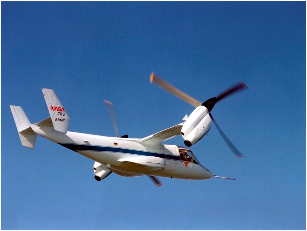
The Bell company brought a history of vertical-lift Tilt-Engine system development to this program when it combined with Boeing in the early 1980s. The company had demonstrated such a system with the XV-3, proving that it was possible to turn wingtip rotors from a vertical position to horizontal, thus providing the thrust to lift the vehicle off the ground and then transition to horizontal flight. The XV-3 was followed by the XV-15, which would closely resemble the V-22, with the XV-15 initially serving as the test vehicle for the V-22. During the early 1980s, the Bell-Boeing competed for the Joint Services Advanced Vertical Lift Aircraft (JVX). Then, on April 26, 1983, the joint team was awarded the contract to begin the preliminary design stage. Initially called the Bell/Boeing-Vertol JVX, the plane would later be given the V-22 Osprey designation, and later, special mission variations carrying the designations of MV-22, HV-22, and CV-22. The 1983 plan called for 1086 of the tri-service VTOLs to be produced with a total procurement cost of $25 billion, with the funding to be shared by the three services. The Navy was to assume the bulk of the obligation with 50 percent contribution. The initial requirement called for the craft to be capable of carrying 24 troops. Power for the Osprey comes from a pair of General Electric T64-GE-717 turboshaft engines, each rated at 6150hp, and the V-22 weighs about 24800kg at maximum take-off weight in a STOL configuration, and about 19840kg in a pure VTOL mode. Its empty weight is just over 14880kg. The rotor diameter is 11.6m, with an overall fuselage length of about 17.4m. With the rotors in the take-off position, the height of the vehicle is just over 6m. The width of the vehicle, with the rotors turning, is almost 26m. Those rotors are capable of rotating through 97 degrees and are constructed of graphite/glassfibre. 33 percent of the weight of the Osprey is fabricated of graphite/glassfibre. The rotors also possess separate cyclic control swashplates for sideways flight and fore-and-aft control during hover. Lateral attitude is maintained by differential rotor thrust. Once the V-22 achieves horizontal flight, the engines have assumed a position parallel to the fuselage.
The V-22 can fly backwards by tilting the rotors back past the 90-degree vertical position. Initial performance requirements for the Osprey were a cruising speed of 480km/h with a range with a full payload of over 1450km. Even though the V-22 carries a cargo designation, it does carry a nose-mounted 12.7mm multi-barrel machine gun. There are redundant systems, along with armor, in critical areas. The composite materials also provide protection, and one engine can power both rotors if required with a cross-coupling capability.
The full-scale development program began in May 1986 with the order for six prototypes. Numbers 1, 3, and 6 were constructed by Bell at Arlington, Texas, and numbers 2, 4, and 5 by Boeing at Wilmington, Delaware.
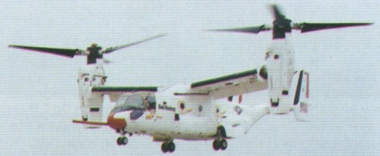
The first V-22 first flew on 19 March 1989.
The V-22 completed its first transition from propeller to wingborne flight on 14 September 1989.
The world’s first operational tilt-rotor transport, the Bell/Boeing’s V 22 Osprey tilt rotor made a successful first flight on 19 March 1989 with “near perfect performance” reported during a series of vertical take offs and landings at Arlington, Texas. The full-scale development program began in May 1986 with the order for six prototypes. Numbers 1, 3, and 6 were constructed by Bell at Arlington, Texas, and numbers 2, 4, and 5 by Boeing at Wilmington, Delaware. The world’s first operational tilt-rotor transport, the Bell/Boeing’s V 22 Osprey tilt rotor made a successful first flight on 19 March 1989 with “near perfect performance” reported during a series of vertical take offs and landings at Arlington, Texas. Wearing grey/green US Marine Corps camouflage, the fourth Bell Boeing V-22 Osprey flew for the first time from Boeing Helicopters flight test centre on 21 December 1989. The flight marked the beginning of V-22 flight test activities at Boeing’s facility in the Delaware Valley. The first flights for the last test vehicle occured in 1991. In 1995, the production of test vehicles resumed with numbers 7 through 10 for vibration, propulsion, USMC, and mating evaluations. Final assembly of the first production V-22 was completed in late 1998. In early 1998, the V-22 accomplished its first night test flight. During the test, the V-22 flew with a neutral density filter which covered the cockpit displays. This allowed the pilots, which were using night vision goggles, to operate the displays in the day mode. Also included in the flight test program was to investigate its capabilities for carry external loads. In one test, the number eight prototype carried a five-ton sling load through the transition phase with a top speed of 425km/h. The test pilot indicated that even though he could feel the load oscillating beneath him, it didn’t affect the craft’s performance. The testing showed that certain loads caused dramatic shifts in the center of gravity of the V-22, which in turn required a change in the attitude of the aircraft. It was determined that that requirement could be accomplished by changing the angle of the engine nacelles. Other tests planned at the time included a sling weight of 6765kg and a Humvee jeep. Early crashes of two prototypes, both in 2000 and resulting in fatalities, nearly did the system in. With pressure mounting to produce, and the general kinks reportedly ironed out, the system was passed for full scale service in 2006. In 1997 low-rate initial production was undertaken for 23 V-22s (called MV-22s) for the USMC. The first MV 22B Osprey tilt-rotor was delivered to the Marines in May 1999. The US Navy has ordered the HV-22 version for SAR duties and fleet logistic support, but cancelled its interest in the Osprey program (HV-22 Combat SAR) in 2001. The projected cost of these first operational V-22s had a unit cost of $32.2 million each, a figure that was down considerably than the $41.8 million projected during the full-scale development program. The plane has attracted international interest, with both Israel and Australia both showing interest in the unique VTOL. Bell is building the wing section, empennage, and powerplant nacelles, while Boeing has the responsibility for the fuselage and landing gear. Bell is also responsible for the final assembly and initial flight tests.
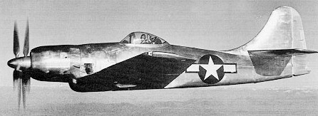
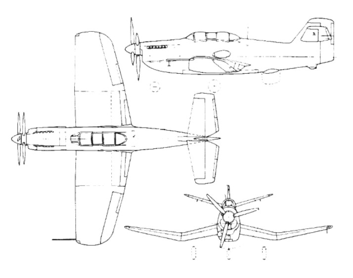
When the changing fortunes of war made it clear to the US Navy that they would need to attack the Japanese home islands, concern was expressed at the need to deploy carriers within easy range of large numbers of land-based aircraft. If the US Navy had available a long-range fighter/fighter-bomber, then it might be possible to engage the enemy without the need to bring the carriers within striking range of land-based defence aircraft. The requirement for such a category of aircraft was communicated to Boeing, which immediately began its design under the designation Boeing Model 400. Submitted to the US Navy, Boeing’s design study was sufficiently interesting to warrant the award of a contract for three XF8B-1 prototypes on 4 May 1943. The first of these aircraft made its initial flight during November 1944, and was immediately seen to be the largest single-seat piston-engine fighter to be built in the USA. In fact, it subsequently proved to be one of the most powerful single-engine fighters to be developed by any nation involved in World War II, for its powerplant consisted of a Pratt & Whitney XR-4360-10 radial piston engine, which had four banks of seven cylinders, the 2237kW power output being used to drive two three-blade contra-rotating metal propellers. Only the first prototype was completed and flown before the end of World War 11, but although the remaining two prototypes were completed and handed over after VJ-Day, the overriding interest in the development of turbine-engined aircraft meant that further test and evaluation of the XF8B-1s was abandoned.
XF8B Crew: 1 Engine: 1 x Pratt-Whitney R-4360-10, 2237kW Take-Off Weight: 9302 kg / 20508 lb Empty Weight: 6132 kg / 13519 lb Wingspan: 16.46 m / 54 ft 0 in Length: 13.18 m / 43 ft 3 in Height: 4.95 m / 16 ft 3 in Wing Area: 45.43 sq.m / 489.00 sq ft Max. Speed: 695 km/h / 432 mph Cruise Speed: 306 km/h / 190 mph Ceiling: 11430 m / 37500 ft Range: 4500 km / 2796 miles Armament: 6 x 12.7mm machine-guns or 6 x 20mm cannons, 1450kg of weapons
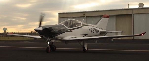
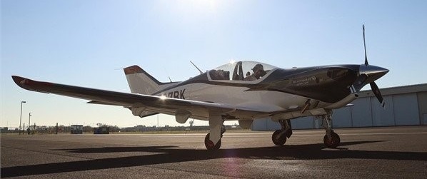
The Blackshape Gabriel trainer aircraft was developed by Italian aircraft maker Blackshape to serve both military and civil pilot training.
The Bk160 Gabriel aircraft base model was launched at the AERO Friedrichshafen trade show held in April 2017, while its upgraded version, designated Gabriel Turboprop (Gabriel-TP), was launched at the Singapore Airshow 2020.
The Gabriel trainer aircraft received design organisation approval and the type certificate in CS-VLA (Very Light Aeroplanes) category from the European Aviation Safety Agency (EASA).
Powered by a turboprop engine, the upgraded trainer variant is intended primarily for military pilot training.
Blackshape plans to cooperate with aircraft manufacturers in South East Asian countries including Vietnam, Myanmar, Philippines, and Malaysia to provide either knock-down kits or full technology transfer for local production of the Gabriel trainer.
Blackshape Bk100-Prime ultralight aircraft serves as the basis for the Gabriel trainer aircraft as well as for ISR and optionally-piloted aircraft versions. A total of 58 Blackshape Prime aircraft were operational in 18 countries, while its special configurations were in service with military operators.
The Gabriel trainer aircraft features aerodynamic fixed-wing design with its design optimised to reduce maintenance and direct operating costs.
Carbon fibre is used in the construction of the aircraft and the fuselage is equipped with low-wing configuration with a wing area of 10.31m² and a wing span of 9m.
The overall height of the trainer is 2.45m, while the overall length is 7.45m. The aircraft has a maximum take-off weight of 850kg, a useful load of 220kg with the capacity to carry 33kg of baggage on-board.
The aircraft is outfitted with an electrical systems with military-grade wiring, temperatures and fuel capacity sensors, anti-blast fuel tanks, and five-point certified safety seat belts. It is also fitted with a ballistic parachute.
The on-board differential braking system is used to steer the aircraft, while the landing gear is electrically actuated.
Gabriel trainer aircraft is equipped with glass cockpit with dual flight controls. It accommodates two pilots in tandem configuration.
The Gabriel can be armed with external payloads, allowing for the training of pilots on light-strike or counter-insurgency (COIN) operations.
The Blackshape Gabriel trainer aircraft is powered by a Lycoming IO-320-D1B engine of 160hp power at 2,700rpm. The engine has a compression ratio of 8.50:1 and drives Hartzell Raptor Series composite propellers in tractor configuration.
The power-plant offers a maximum speed of 164k at sea level and can reach altitudes of 15,000ft. The maximum rate of climb is 1,550fpm, while the maximum endurance is 192 minutes. The trainer requires a take-off distance of 250m and the landing ground roll of 190m.
The load factor of the aircraft is +4.4/-2g. Equipped with Roll Royce turboprop engine, the Gabriel-TP variant can attain a true airspeed of 200k at sea level.
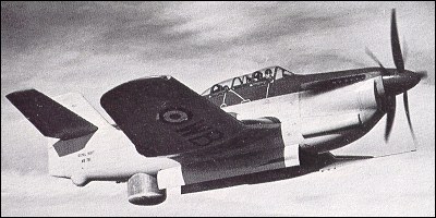
The first prototype, two-seat B-54 with the Rolls-Royce Griffon 56 piston engine and counterrotating propellers flew on 20 September, 1949. The second prototype with a crew of three flew on 3 May 1950. The third prototype was a turboprop-powered B-88 flown on 19 July 1950.
Y.B.1 Double Mamba powered 3 seat and two set Y.A.5 Griffon powered
No series production followed.
B-88 Engine: 1 x Armstrong Siddeley Double Mamba, 2200kW Take-Off Weight: 5938 kg / 13091 lb Wingspan: 13.46 m / 44 ft 2 in Length: 13.0 m / 42 ft 8 in Height: 5.11 m / 16 ft 9 in Max. Speed: 515 km/h / 320 mph Crew: 3
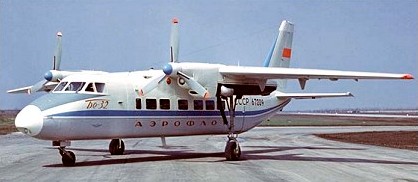
Beriev’s Be-32 were built for the ‘commuter’ programme in the 1970s, first flown in 1976. The LET 410 was selected, ten were built, and the Be-32 was cancelled.
Engine: 2 x Glushenkov TVD-10 turboprops, 708kW Take-off weight: 5860 kg / 12919 lb Wingspan: 17.0 m / 55 ft 9 in Length: 15.7 m / 51 ft 6 in Height: 5.46 m / 17 ft 11 in Wing area: 32.0 sqm / 344.44 sq ft Cruise speed: 480 km/h / 480 km/h Range: 1300 km / 808 miles Passenger cap: 16
The Beriev Be-30 short-haul transport is the first landplane to be designed and developed by the Beriev design bureau. Seen publicly for the first time at the Soviet Aviation Day display at Domodedovo in 1967, it also appeared at the 1969 Paris Air Show. Designated Be-30, and allocated the NATO codename ‘Cuff, it was reported to have flown for the first time on 3 March 1967. A high-wing monoplane, the Be-30 was of all-metal structure and introduced features such as metal bonding, spot welding, and the use of stiffened skin panels of light alloy honeycomb. The retractable tricycle landing gear incorporated stalky main units, retracting into the rear of the engine nacelles. Power-plant of the prototype consisted of two 552kW Shvetsov ASh-21 radial piston engines, but two Glushenkov TVD-10 turboprops were used to power the very small number of production aircraft. Accommodation was provided for a crew of two and 14 passengers, and features included air-conditioning and blind-flying equipment that incorporated an autopilot and an automatic approach system.
Engines; two Glushenkov TVD-10 turboprops Pax cap: 14
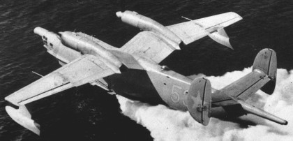
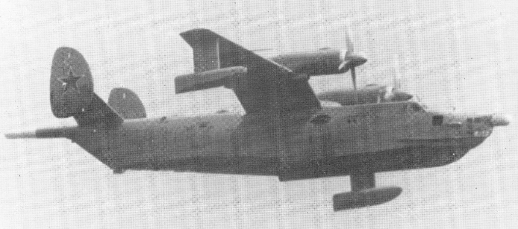
The lessons learned in the design of the R-1 and Be-10 were incorporated in the design of a much improved flying-boat based loosely on the Be-6 and identified originally by NATO as a re-engined version of the older type.
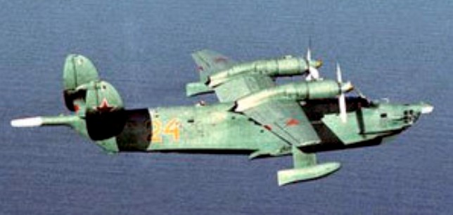
The Be-12 Tchaika (Seagull), designated M-12 in AV-MF service, has the gull-wing layout and twin tail of its predecessor. The greater power and lighter weight of the turboprop engines have permitted a forward extension of the hull, with a new planing bottom. The prominent spray suppressor around the bows of the Be-10 is also a feature of the turboprop aircraft.
The addition of a retractable landing gear makes the Be-12 amphibious. MAD (magnetic anomaly detection) gear extends 15 ft behind the tail. The search and mapping radar projects far ahead of the glazed nose, and much of the hull is filled with equipment and there is a weapon and sonobuoy bay aft of the wing with watertight doors in the bottom aft of the step.
The Be-12 turboprop aircraft, first seen at the 1961 Moscow Aviation Day at the same time as the swept-wing Be-10, has fast become the Soviet Union’s standard large marine aircraft. The weight-lifting capability of the Be-12 was demonstrated in a series of class records for amphibians set up in 1964, 1968 and 1970, suggesting a normal weapons load as high as 5000kg. The Be-12 can load on the water through large side hatches in the rear fuselage, and stores can be dropped through a watertight hatch in the hull aft of the step. Be-12s have set many class records for speed, height and load-carrying. They were based all around the Soviet shores and in Egypt and, possibly, other countries. NATO code name ‘Mail’. It is also believed to have been used for mapping, geophysical survey and utility transport. By Soviet standards the type was not built in large numbers, only 95 being reported in service in the late 1980s.
Be-12 (M-12) Tchaika Engines: 2 x Ivchenko AI-20D single-shaft turboprops, 4,190 ehp / 2940kW Wing span: 97 ft 6 in (29.7 m) Wing area : 1030.007 sqft / 95.69 sq.m Wing load : 63.14 lbs/sq.ft / 308.00 kg/sq.m Length overall: 99 ft (30.2 m) Height on land: 22 ft 1½ in (7 m) Empty weight: approx 48.000 lb (21.772 kg) Max take off weight : 65047.5 lb / 29500.0 kg Max. speed : 329 kts / 610 km/h / 379mph Cruising speed 199 mph (320 km/h) Initial climb rate : 2992.13 ft/min / 15.20 m/s Service ceiling 38.000 ft (11582 m) Range with full equipment: 2160 nm / 2.485 miles (4000 km) Armament: at least 6600 lb (3000 kg) sonobuoys and AS bombs in internal weapon bay; one to three external hard points for stores under each outer wing. Crew: 6-10
In 1965, the U.S. Army issued a Request for Proposal for what it called the Composite Aircraft Program. Composite, in this case, was for a vehicle that would have both helicopter and airplane characteristics, specifically, looking for a single aircraft to replace both the CH-47 helicopter and the C-7 “Caribou”. Three contractors were selected to perform design studies in 1966 and Lockheed and Bell were chosen to perform further exploratory definition studies, which were completed in September 1967. However, the Army dropped the development due to limited funds. Bell decided in 1968 to continue development for a proposed civil tilt-rotor aircraft, designated the Model 300. Initial work led to the design for a 4285kg aircraft powered by two Pratt & Whitney PT-6 engines powering 7.6m diameter rotors. One-fifth scale aerodynamic and aeroelastic models were built and tested extensively from 1969 through 1973. Full size rotor and rotating mechanisms were whirl tested to determine their hover performance and then tested in 1970 at the NASA Ames 12m x 24m wind tunnel at various rotation speeds, angles, and airspeeds up to the maximum tunnel speed of 370km/h. The rotor met or exceeded all performance and stability predictions. Then, in 1972, NASA and the U.S.Army Air Mobility Research and Development Laboratory jointly started the Tiltrotor Research Aircraft Program. Since the Tiltrotor Research Aircraft Program was to be strictly a research program and would not lead to the production of an operational aircraft, costs were to be kept under control by not making weight minimization a major factor and encouraging the use of off the shelf components. Advanced technologies like fly-by-wire and composite structures were to be avoided. Weight growth and performance shortfalls would be tolerated in order to minimize cost and schedule impacts. Even the number of aircraft to be built was a factor. The two aircraft option was selected because of the high accident rate experienced by most other VTOL research programs. Bell’s proposal started with the Model 300’s design and evolved it into Model 301. Bell kept the rotor and transmission, but replaced the engines with the more powerful Lycoming T-53 because of the requirement to hover with only one engine and the greater empty weight and useful loads required. Another benefit of the engine switch was that the T-53 already had an oil system that could operate with the engine pointed vertically, which had been developed for the CL-84 program. Bell’s proposal was submitted on January 22, 1973, and comprised 300 volumes weighing 350kg. Bell’s proposal was selected in April 1973. NASA awarded contract NAS2-7800 for $28 million for the final design, fabrication, and preliminary testing of two XV-15s on July 31. The total estimated cost of the six-year program was $45 million. The 12.8m long fuselage design was of a conventional aircraft, semi-monocoque, , and using light alloy material. There was no fuselage pressurization, and the structure was stressed from +3 to -0.5 G. The airframes were designed for minimum service lives of 1000 flight hours over five years. The tricycle landing gear came from the Canadair CL-84. It utilized Goodyear magnesium main and nose wheels, and Goodyear hydraulically operated magnesium/steel disc brakes. The full-swiveling nose wheel incorporated shimmy dampers and a centering device. It retracted into a bay forward of the cockpit. The main wheels retracted into external pods on each side of the fuselage. A switch on the main gear strut prevented inadvertent gear retraction and tilting of the pylons more than 30 degrees from vertical when the aircraft was on the ground. The landing gear was structurally designed to withstand a touchdown sink rate of 3m per second at full gross weight. A 14500kg/sq.m nitrogen gas system provided for emergency extension in the event of a hydraulic failure. The H-tail consists of a horizontal stabilizer with a vertical stabilizer on each tip. This configuration was selected to provide improved directional stability at and near zero yaw angles. Rockwell International’s Tulsa Division built the fuselage and tail units under subcontract. Two pilots sat side-by-side in Rockwell-Columbus LW-3B ejection seats, entering through a door on the right side of the cargo compartment. The flight deck was heated, ventilated, and air conditioned, but not the cargo compartment. The cabin could accommodate nine personnel if not filled with test equipment. The wing measures 9.75m across, has a constant chord measuring 1.6m, and a area of 15.7sq.m (one of the design requirements was that the XV-15 be able to fit in NASA Ames’ 12m x 24m wind tunnel, which influenced the wingspan and rotor size). It is swept forward 6.5 degrees, not for any futuristic aerodynamic reasons, but to insure there would be adequate clearance when the rotor blades flex in airplane mode. Wing dihedral is 2 degrees. Along the trailing edge, a flap measuring 1sq.m occupies the inboard third, and a flaperon measuring 1.85sq.m occupies the outer two thirds. The flaps can be deflected down to 75 degrees to help provide additional lift at low speeds. In hover, the flaps and flaperons deflect downward to reduce slipstream interference by the wing. The problems with the wing/rotor/pylon stability that plagued the XV-3 were eliminated by designing a very stiff wing and nacelle/wing attachment, and by placing the rotor hub as close to the wing as possible. Each wing holds two fuel bladders that form a single crashworthy fuel tank in each wing. Together they hold a total of 830 litres. The pump in each wing tank is powered from a different electrical system. In the event of a pump failure, both engines can feed from the same tank, or in the case of an engine failure, one engine can feed from both tanks. Cross feeds activate automatically in the event of a pump failure to assure uninterrupted fuel flow to both engines. In the event of a complete loss of electrical power to both pumps, the engine driven pumps still can maintain adequate fuel flow. An Avco Lycoming LTC1K-4K engine, a modified version of the standard T53-L-13B engine, is mounted at each wing tip. They are rated at 1250shp for continuous operation, 1401shp for 30 minutes, 1550shp for 10 minutes for take-off, and 1802shp for two minutes for emergency power. Power is transmitted from the engines to the rotors using a coupling gearbox and transmission, which reduce the engine speed of approximately 20000 revolutions per minute down to a rotor speed of about 565 revolutions per minute in hover. The three-bladed, semi-rigid rotors measure 7.6m in diameter and have a 36cm chord. They were made of stainless steel and have a large amount of twist. (In July 1979, Bell received a contract from Ames for preliminary design of a composite rotor blade that would offer improved performance and increased life expectancy, compared to the existing metal blades. A set eventually was tested, but did not work well.) There are no flapping hinges, but the rotors can flap forward or aft as much as 6 degrees. To assure power to both rotors in the event of an engine failure, a shaft that runs through the wing interconnects the two transmissions. As a result of the interconnect, both rotors turn when the first engine starts. In the event of a double engine failure, both rotors will autorotate at the same speed. The nacelle tilt can be varied from horizontal to 5 degrees aft of vertical. Interconnected double ballscrew actuators operate the tilt mechanism in each nacelle. This assures that both nacelles always will be at the same position. The interconnected drive shafts and redundant tilting mechanisms permit single engine operation and fail-operate tilt capability. The cockpit has dual controls and resembles a helicopter cockpit, including a collective stick. The flight controls are designed to permit single pilot operation from either seat. In airplane mode, the control columns and rudder pedals work conventionally. In hover mode, the stick functions as a cyclic pitch controller. The mechanical mixing unit does everything needed to convert the controls from the helicopter mode to the fixed wing mode. Control authority between helicopter and airplane mode is phased in as a function of the nacelle tilt angle. This includes changing the rotors from cyclic pitch control in vertical flight to constant speed control for fixed wing flight. In airplane mode, the collective lever can still be used as a power lever. Moving the collective lever causes the throttles on the center console to move. Two switches, mounted on the collective lever and operated by the pilot’s thumb, control the nacelle tilt angle. One pivots the nacelles from end to end in about 12 seconds and allows them to be stopped at any position. The other switch moves the nacelles between pre-selected angles of 0, 60, 75, and 90 degrees (relative to horizontal). To rotate the nacelles, electrical valves activate hydraulic motors. In the event of a complete electrical system failure, the pilot can manually open the valves using T-handles in the cockpit. This will drive the nacelles to the helicopter position. Sperry Rand built the original navigation/guidance system. A digital computer provides navigation and control information to the pilot using advanced mechanical and electronic displays. The Calspan Corporation of Buffalo NY designed the Stabilization Control Augmentation System to improve its flight characteristics. The XV-15 does not incorporate fly-by-wire. Ailerons, elevator, and rudder are hydraulically boosted with a triple hydraulic system. They remain active in all flight modes.
The XV-15’s empty weight is 4315kg with a vertical take off weight of 5865kg. This allows 495kg for instrumentation, 180kg for pilots, and 630kg of fuel, while leaving a few left over for growth. Original estimated performance included a maximum level speed of 610km/h, service ceiling of 8845m, and a range of 800km. None of these goals ever were achieved, but the XV-15 did achieve its primary objective of proving the practicality of the tilt rotor concept.
In April 1974, Rockwell International (Tulsa Division) received a contract for the construction of the fuselage and the tail assembly of the two XV-15 airframes. On 2 October, 1975, components of the first prototype were delivered to Bell Helicopter in Fort Worth where final assembly would be undertaken. Aircraft No.1 (c/n 00001, N702NA) was rolled out, at Arlington, on 22 October, 1976. Before tiedown dynamic tests simulating all flight modes, the XV-15 No.1 underwent an extensive integration checkout. Ground runs began in January 1977, and included 100 hours of system qualification tests on an elevated test stand in both the helicopter and airplane modes to demonstrate that the aircraft met final flight qualification requirements. The first hovering flight was performed on May 3, 1977, followed by hover and low speed evaluations. This short test effort consisted of only three hours of hovering during May. No problems that warranted corrections were uncovered. Following these flight tests, the transmissions and rotors were torn down, inspected and reassembled. Because of NASA’s insistence on full-scale wind tunnel tests before attempting a conversion, aircraft #1 was shipped by C-5A to NASA’s Ames Research Center in March 1978 for wind tunnel tests. These tests were conducted in the Ames 12m x 24m foot wind tunnel in May and June 1978. Twenty hours of tunnel tests were performed at airspeeds between 110 and 330km/h. Configurations consisted of the rotors in helicopter and airplane positions, and numerous intermediate positions that would be encountered during transition. No unusual characteristics were noted in any of the tests conducted. Following the wind tunnel tests, the #1 aircraft was torn down and refurbished at NASA Ames.
The second XV-15, #N703NA, was nearing completion. Since the program lacked funds to keep two aircraft on flight status, testing resumed with the #2 aircraft, beginning ground tests in August 1978 at Arlington. Numerous minor problems plagued the aircraft during these tests, including a stress corrosion crack in the left engine gearbox, a clutch misengagement, and foreign object damage within the transmission. It made its first hovering flight on April 23, 1979, with Ron Erhart and Dorman Cannon, Bell’s XV-15 project pilot, at the controls. Conversion tests soon began, starting by rotating the nacelles 5 degrees forward on 5 May 1979. Successive tests gradually rotated the nacelles closer to horizontal, until the first complete conversion was made on July 24, 1979. The XV-15 also achieved a forward speed of 295km/h on this 40 minute flight. On 21 April, 1980, No.2 prototype reached 485km/h at 2530m. In one year of testing, aircraft No.2 logged 40 hours flying.
The Navy became interested in the XV-15 and because of continuous funding shortfalls, the Naval Air Systems Command began providing funding in 1979 and 1980 to insure the XV-15 flight testing would proceed up through the completion of envelope expansion flights. In exchange, the Navy would be allowed to perform flight evaluations.
During the contractor test program, all potential failures were simulated in actual flight or on the ground. On December 5, 1979. an actual engine failure occurred when the turbine seized. The transmission interconnect system worked properly, and both rotors continued to turn as designed. The predicted speed of 555km/h true airspeed was demonstrated with maximum rated power at a 4880m density altitude in June 1980. The contractor flight test phase was completed in August 1980. The basic conversion corridor and airspeed/altitude envelope up to 16,000 feet was demonstrated. About 100 full conversions were made. Some resonance problems were uncovered, as is normal in any helicopter development, but they were fixed quickly. Upon completion of the contractor flights, XV-15 #2 was shipped to NASA’s Dryden Flight Research Center for continued testing, where it was joined by aircraft #1. Both XV-15s then operated at Dryden for a short period. XV-15 #1 returned to Bell in September 1981. Flight testing by both NASA and Bell continued into the 1980s, and the two XV-15s proved to be virtually free of any significant problems. Additional accomplishments that were demonstrated included:
1.7 hour cruise endurance in airplane mode.
Cruise speed of 425km/h.
Take off as helicopter, fly twice as fast as a helicopter, and deliver payloads on half the amount of fuel when traveling distances of greater than 185km.
Autorotation descents in helicopter mode, but never to a full touchdown.
STOL take-offs with the nacelles tilted between 60 and 70 degrees, at the maximum gross weight of 6765kg. For taxiing on wheels, it was found that tilting the nacelles forward of vertical only 1 degree was enough to start the XV-15 moving forward. Tilting the nacelles aft of vertical brings the aircraft to a quick stop. The XV-15 tends to rock a bit more than other aircraft because of the weight of the engines and props all the way out at the wing tips. In hover, roll control is provided by differential rotor collective pitch, pitch control by cyclic pitch, and yaw by differential cyclic pitch. For maneuvering in the hover mode, many of the maneuvers normally performed by moving the cyclic control are done by tilting the nacelles. A combination of rotor angle and cyclic pitch also is used to vary the pitch attitude without moving forward. By tilting the rotors forward and simultaneously putting in aft cyclic control, the nose will pitch down, giving improved visibility over the nose. Vertical liftoff is very easy, as the XV-15 holds attitude on liftoff. Lateral movement is accomplished by banking slightly so that the thrust has a small side component. The XV-15 can travel sideways at 65km/h with no tendency to turn into the wind. It can hover backwards up to 65km/h. Touchdown surfaces can have an uphill or downhill slant of up to 15 degrees. Single engine performance is relatively poor, with single engine hover possible under only a very few conditions. During conversion from hover to conventional flight, there is a tendency to lose lift and sink, requiring the pilot to add power, but this is normal on all VTOL aircraft. With the nose up and full aft stick, level stalls in the clean configuration give a slight vibration at 205km/h. The aircraft will begin to sink, but there is no wing drop or other bad effects. In helicopter autorotation mode, the best descent rate of 11m/s is achieved at 140km/h. At 165km/h, the descent rate increases to 20m/s. For final approaches, pilots use nacelle tilt angle instead of pitch inputs to control airspeed. The 630kg of fuel contained in the wings proved to allow for only about a 280km range. An auxiliary tank holding an additional 405kg eventually was added to the fuselage, which increased the range to about 520km. In March 1982, aircraft #1 made a demonstration tour of East Coast facilities, which included seven flight demonstrations at six different locations in eight days. One flight included a stop at the helipad at the Pentagon. While on the tour, the XV-15 flew 4815km and needed only routine daily preflight maintenance. Following this East Coast tour, #1 was modified at Bell’s Arlington facility to perform an electronics mission evaluation. Items added included an APR-39 radar warning system and chaff dispenser system. The aircraft departed for NAS China Lake in California in May, then on to Ft. Huachuca in Arizona in June, and finally on to San Diego for sea trials. Shipboard evaluations were performed aboard the amphibious assault ship USS “Tripoli” off the San Diego coast in July 1982. Fifty-four vertical landings and take-offs (of which five were STOL take-offs) were performed. Other mission related evaluations included over-water rescue and simulated cargo lifting, which were demonstrated in May 1983, and simulated air-to-air refueling, which was performed in September 1984. By 1986, both aircraft had accumulated a total of 530 flight hours, made 1500 transitions, and reached an altitude of 6860m (while still maintaining an 4m/s climb capability). In March 1990, #1 set numerous time to climb and sustained altitude records for this class of aircraft. These included a climb to 3000m in 4.4 minutes and to 6000m in 8.46 minutes, without even performing extensive climb tests to develop an optimal climb profile. It also sustained an altitude of 6860m with a dummy payload of 990kg in addition to more than 450kg of test instrumentation. Under the new JVX programme Joint Services Advanced Vertical Lift Aircraft Program) the XV-15 served as test-bed. In direct relation to the JVX programme, XV-15 No.1 was tested in Fort Huachuca to evaluate its ability to accomplish SEMA missions (Special Electronics Mission Aircraft); the aircraft was sent to China Lake to measure its radar signature and, on 2-5 August, 1982, off San Diego, Lieut-Cdr John Ball and Dorman Cannon conducted the initial shipboard evaluation on board the amphibious assault ship USS Tripoli (LPH-10). This evaluation included vertical and short rolling take-offs, hovering flights and vertical landings. On this occasion, one of the 54 XV-15 landings was the ship’s 60.000th. The aircraft was then sent back to Fort Worth to undergo a complete overhaul and to receive several modifications. By the end of August 1982, the two prototypes had logged 289 hours of flight testing. The two XV-15s were then used in a research programme to explore the limits of the operational flight envelope and assess its application to military and civil transport needs. Late in 1987, the XV-15, piloted by Dorman Cannon and Don Borge, demonstrated its capabilities in the civil transport role at Washington and Chicago. The Chicago demonstration was conducted from Miegs Field in the very heart of the city. As of June 1990, XV-15 #1 was based at Bell Helicopter’s Flight Research Center in Arlington, TX, for continuing engineering development. XV-15 #2 was based at Ames for continuing tilt-rotor research. The two aircraft had accumulated 825 hours. By 1990 the XV-15 was flown by over 185 pilots with widely varying experience and capability levels, including several low-time private pilots. Numerous admirals, generals, and at least one U.S. senator and one service secretary flew as guest pilots. Each flight consisted of a brief demonstration of helicopter, conversion, and airplane modes by a Bell test pilot. The guest pilot then took over the controls. After a few minutes of familiarization, he was talked through an airplane stall, single engine operation, and conversion/ reconversion at altitude. They then return to the airport for several take-offs and landings, usually converting to airplane mode and back to helicopter mode each trip around the pattern. Guest pilots rated the XV-15 as easy or easier than a helicopter to hover. Conversion was unanimously said to be straightforward, and with a low workload. Handling qualities in airplane mode were excellent. Most also noted the low interior noise and smooth ride. FAA test pilots also flew the XV-15 in order to evaluate its potential for certification of a civil tilt rotor aircraft. While they saw no technical reasons for not being effective in the civil role, they determined that a review of Part 25, which sets standards for large transport aircraft, and Part 29, which sets standards for helicopters, would be needed in order to establish appropriate certification criteria. XV-15 #1 remained in service at Bell’s flight research center, where it was used as a concept demonstrator and marketing tool for the V-22 Osprey that was by then being developed. It was flown regularly until August 1992, when it was damaged beyond economical repair. A mechanical failure in the control system caused the aircraft to roll over while it was hovering. The crew was not injured, but the wing and one nacelle sustained extensive damage. At the time of the incident, #1 had flown nearly 841 hours. The forward fuselage was salvaged and put to use as a simulator to help develop Bell’s upcoming civil tilt rotor aircraft. XV-15 #2 remained at Ames through the 1980s. In 1986, it was fitted with composite rotor blades built by Boeing Helicopter. Sporadic testing was accomplished through 1991, when it was stopped due to a problem with the blade cuff that resulted in an emergency landing. While the blade cuff was being re-designed, NASA decided to put the airframe down for a major airframe inspection that would be due soon, anyway. Program funds again ran out before the inspection could be completed. #2 would remain partially disassembled until mid 1994. It had accumulated just over 281 hours. With Bell anxious to resume tilt rotor development, they established a Memorandum of Agreement with NASA and the Army in 1994 which transferred XV-15 #2 to Bell and allowed them to return it to service at no cost to the government. The disassembled aircraft was shipped to Arlington, Texas, and the refurbishment and inspection began in mid 1994. The original metal rotor blades were put back on, and the aircraft resumed flight testing in March 1995. Much of Bell’s recent research has focused on reducing noise in order to make civil tilt rotor more acceptable for operating in crowded urban areas. Tests were being conducted to determine the major sources of noise. As of the end of 1998, the remaining XV-15 had accumulated a total of 530 flight hours and remained in service at Bell’s Arlington facility to continue developing and refining Tilt Rotor technologies.
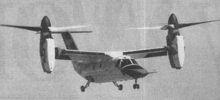
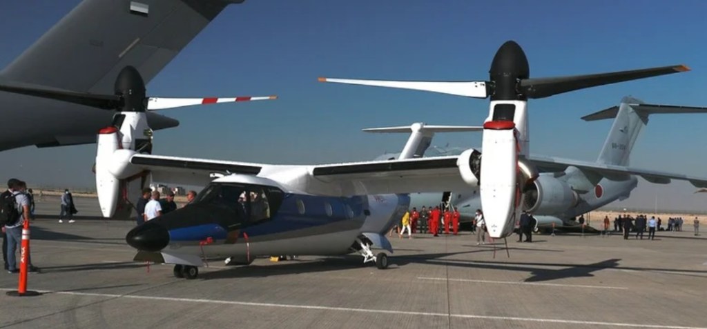
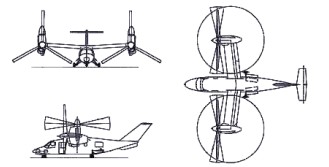
Bell and Boeing revealed in February 1996 that studies were in progress for a nine-passenger civil tiltrotor aircraft in the 6,350kg weight class, with the preliminary designation D-600. On 18 November 1996, the two companies announced that a joint venture was being established to design, develop, certify and market a six- to nine-passenger civil tiltrotor as the Bell Boeing 609. The machine has engines which pivot 90 degrees so it can take off vertically like a helicopter, then fly horizontally like a plane. Boeing withdrew as a partner on 1 March 1998 and Bell formally announced at the Farnborough Air Show in September 1998 that they had teamed with Agusta. Agusta was investing and participating in BA609 development and was to be responsible for assembly of BA609s sold in Europe and elsewhere. Preliminary design review completed May 1997. Manufacture of parts for the prototypes began in Philadelphia, August 1997, and a full-size mockup was exhibited at the Paris Air Show in June 1997. With a T-tail configuration and composite cross-shafts to keep both prop rotors turning in event of engine failure. Manual screwjack facility exists whereby the prop-rotors can be tilted into helicopter mode if the cross-shafts fail. Designed using three-dimensional CATIA digital computer design system, the airframe has design life of 20,000 flight hours. The aluminium fuselage structure has composites skinning and composites wings. The undercarriage is a retractable tricycle type, with twin nosewheels and single wheel on each-main unit. Control is by a BAB Systems triplex digital fly-by-wire flight control system, with Dowty Aerospace actuators. The T tail has conventional elevators and no rudder. Two-segment trailing-edge flaperons are fitted. Two 1,447kW Pratt & Whitney Canada PT6C-G7A turboshaft enginesc are installed in tilting nacelles at the wingtips, each driving a three-blade proprotor. Nacelle transition is achieved in 20 seconds. Fuel is in integral wing tanks with a usable capacity of 1,401 litres, and provision for auxiliary fuel tanks. The airframe carries a crew of two, side by side on flight deck, with dual controls, and a maximum of nine passengers in the standard aircraft. A crew and passenger door is on the starboard side, forward of wing. The cockpit is pressurised and air conditioned; pressurisation differential 0.38 bar. Ground-running trials began on 6 December 2002 and the first flight of the prototype (N609TR) took place (in the vertical mode only) on 7 March 2003 in Arlington, Texas, rescheduled from late 2002. The Bell/Augusta Aerospace Co said its BA 609 tilt-rotor aircraft flew at an altitude of about 15m in its first test flight. Four prototypes were produced for a 36-month flight test programme leading to certification in January 2007 under FAR Pt 25 (fixed-wing aircraft) and Pt 29 (helicopters), plus Pt 21.17(b) Special Conditions for unique components. The first prototype were used primarily for expansion of flight envelope, while the second, third and fourth airframes were dedicated to systems certification, avionics and icing approval, and FAA function and reliability, respectively.
Leonardo AW609
The order book opened on the 2nd of February 1997 at Heli Expo, with the first order placed soon after by an unspecified customer. A total of 70 were ordered by 40 customers in 18 countries by March 2003. A briefing was given to the US Coast Guard, late 1997, followed by a demonstration by the XV-15 tiltrotor concept demonstrator aboard the Coast Guard cutter Mohawk off Key West, Florida, in May 1999. In 1998 Bell Helicopter Textron acquired Boeing’s 49% interest in the Bell-Boeing 609 civil tiltrotor and has assumed full ownership.
Bell 609 Engine: 2 x Pratt & Whitney PT6C-67A, 1360kW / 1850hp Empty weight: 6300kg Max speed: 510km/h Range: 1390km Crew: 2 Passengers: 6-9