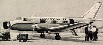
The Guarani I light transport first flew in prototype form on 6 February 1962 and utilised about 20% of the structural components of the IA.35 Huanquero. Power was provided by two 633kW Turbomeca Bastan IIIA turboprop engines. The Guarani II was developed from it and the prototype flew for the first time on 23 April 1963. It was placed in production for the Argentinian Air Force for communications, photographic (with the Military Geographic Institute) and executive transport duties, while the Navy received one as a staff transport. A total of 41 G.IIs were built.
Engines; 2 x Turbomeca Bastan IVA Wingspan; 19.6 m / 64 ft 4 in Length; 15.3 m / 50 ft 2 in Height; 5.6 m / 18 ft 4 in Wing area; 41.8 sq.m / 449.93 sq ft Max take-off weight; 6500 kg / 14330 lb Empty weight; 4000 kg / 8819 lb Max. speed; 490 km/h / 304 mph Cruise speed; 485 km/h / 301 mph Ceiling; 3100 m / 10150 ft Range w/max.fuel; 2500 km / 1553 miles Range w/max.payload; 2000 km / 1243 miles Crew; 1 Passengers; 10-15
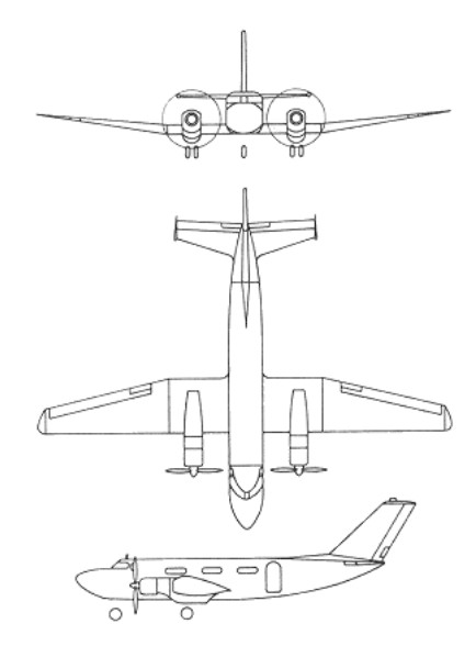
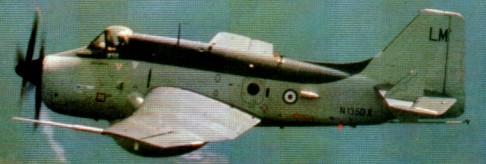
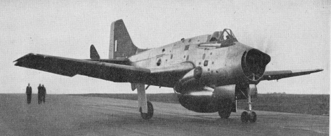
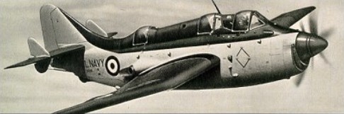
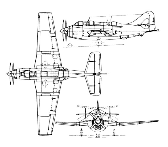
Built as a carrier-based anti-submarine warfare (ASW) aircraft, Fairey’s prototype was known initially as the Type Q. First flown on 19 September 1949, the first and second prototype were of two-seat configuration. The third prototype (which first flew on 10 May 1951) was more representative of production aircraft with three cockpits to accommodate the pilot (forward), observer/navigator (centre), and radio-radar operator (aft).
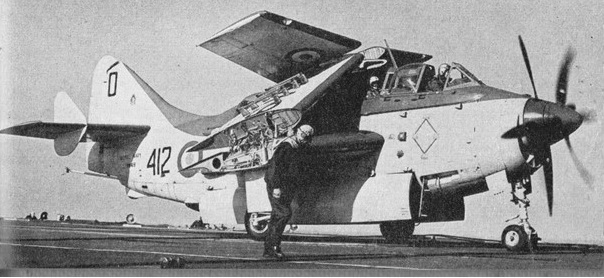
Of all-metal stressed-skin construction, this large mid-wing monoplane had mechanically folding wings to facilitate carrier stowage, and its deep fuselage was able to carry all its major strike weapons internally. Up to 16 air-to-surface rockets could be carried beneath the wings. The Armstrong Siddeley Double Mamba turboprop engine, comprised two turbine engines with individual co-axial contra-rotating propellers. Either engine could be shut down independently and its propeller feathered so that the aircraft could cruise economically. It was the first aircraft in FAA service to combine the ‘hunter/killer’ role for ASW.
The first operational squadron was formed on 17 January 1955. AS.1 and AS.4 aircraft, as well as T.2 and T.5 trainers, served with the FAA until gradually superseded by Whirlwind helicopters from 1958.
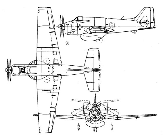
The Gannet AEW.3 was first flown from Northolt on 20 August 1958, designed for airborne early-warning duties with the Royal Navy. One of the newcomers at the 1958 Farnborough display was the prototype Gannet AEW.3.
Gannet AEW.3
On 1 February 1960 the Gannet AEW.3 early-warning variant began to enter service, having a more powerful Double Mamba engine and a large radome mounted beneath the fuselage. Its pilot was accommodated in a forward cockpit and the two radar operators were seated within the fuselage. A total of 44 of these were built, the later examples by Westland Aircraft which took over the Fairey factories in 1960. The AEW.3 which went to sea aboard HMS Ark Royal in the summer of 1970 were the last Fairey-designed first-line aircraft to serve with the FAA.
The RAAF operated 36 Gannet, ordered in 1953. Four Gannet T.2/T.5 were also ordered in 1953. The first delivered to the RAAF during October 1955 and the last in September 1958.
The AS.4 was also used by the German Navy (15) and Indonesian Navy (16).
Fairey Gannet AS1/4 Engines: One 1,950 eshp Armstrong Siddeley Double Mamba 100 turboprop / One 3,035 eshp Armstrong Siddeley Double Mamba 101 turboprop Wing Span: 54 ft 4 in Length: 43 ft Height: 13 ft 8.5 in Empty weight: 15,069 lb Loaded weight: 19,600 lb Initial Rate of Climb: 2000 ft/min Ceiling: 25,000 ft Speed: 299 mph Range: 662 miles Crew Three Armament: 2 x torpedoes in bomb bay / 16 x 60 lb rocket projectiles under wings
AS.4 Engine: One 3,035 eshp Armstrong Siddeley Double Mamba 101 turboprop Wingspan: 54 ft 4 in Length: 44 ft 6 in Wingarea: 482.8 sq.ft Empty weight 15,069 lb MTOW: 21,600 lb Max speed: 310 mph Service ciling: 25,000 ft Max range: 943 mi at 196 mph
Fairey Gannet T.2 Engines: 1,950 eshp Armstrong Siddeley Double Mamba 100 turboprop – T2 Empty weight: 15,069 lb Loaded weight: 19,600 lb Wing Span: 54 ft 4 in Length: 43 ft Height: 13 ft 8.5 in Crew: 4 Initial Rate of Climb: 2000 ft/min Ceiling: 25,000 ft Speed: 299 mph Range: 662 miles Armament: Guns: None / Bombs: 2 x torpedoes in bomb bay / 16 x 60 lb rocket projectiles under wings
Fairey Gannet T.5 Engines: 3,035 eshp Armstrong Siddeley Double Mamba 101 turboprop – T5 Empty weight: 15,069 lb Loaded weight: 19,600 lb Wing Span: 54 ft 4 in Length: 43 ft Height: 13 ft 8.5 in Crew: 4 Initial Rate of Climb: 2000 ft/min Ceiling: 25,000 ft Speed: 299 mph Range: 662 miles Armament: Guns: None / Bombs: 2 x torpedoes in bomb bay / 16 x 60 lb rocket projectiles under wings
With the concept of the convertible helicopter proved on a small scale with the Jet Gyrodyne, the proposal put forward by Dr. J.A.J. Bennett and Captain A.G. Forsyth in 1947 for a large compound helicopter looked viable, and various designs were considered. The first mention of the project and of the name Rotodyne was made in March 1951 by the Ministry of Civil Aviation’s Interdepartmental Helicopter Committee in its initial report. No details were given, but it was reported to have two propeller-turbines and tip-jets, to have a cruising speed of 217km/h and capacity for 23 passengers. This was probably the Mamba-engined project.
Confirmation of the need for such an aircraft was provided by the British European Airways specification of December 1951 for a short/medium-haul ‘BEAline Bus’. Five manufacturers submitted projects to meet this earlier specification for a 30/40-passenger aircraft. Fairey’s original proposal again incorporated the projected D.H. powerplants. These were in two underwing nacelles, in each of which was located a main gas-turbine driving an auxiliary compressor and, mounted in tandem, a second turbine driving a constant-speed propeller through a reduction gear. Air for this turbine was tapped from the auxiliary compressor of the main engine. The rotor was four-bladed, with pressure-jet units at the tips.
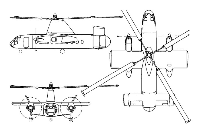
The Gyrodyne had rear clam-shell doors allowing the loading of large motor vehicles. A forward-located door permitted simultaneous entry and exit of passengers. The passenger compartment was 14m long, 2.4m wide, and 1.8m in height. The tail lower tail surfaces were oriented straight down, while the upper surfaces were canted at about a 45 degree angle. The final version, with two Elands driving propellers and/or auxiliary compressors, was outlined in 1953 and formed the subject of a Ministry of Supply research contract. This became the definitive prototype, leading later, without very fundamental changes, to the proposed production Rotodyne FA-1, or Type Z, of 1959-60, with planned seating for up to 70 passengers. For this, XH249 (F.9430), the Elands could not provide the power required, so two 5,250shp Rolls-Royce Tyne propeller-turbines were envisaged. But in hot/high conditions, even this power would have been only just adequate in the engine-failure on take-off case, and Rolls-Royce suggested separate air-producing engines to supply the tip-jets.
Fairey Rotodyne – Eland engines
The proposed solution was to install, at the rear of each nacelle, an RB.176 in which a lightweight gas-turbine drove an auxiliary compressor. By this use of separate propulsion and lift power there would be a considerable increase in weight, but the arrangement gave worthwhile gains in off-design conditions. The Fairey pressure-jet unit for the prototype consisted of a circular-section flame-tube fed by three air pipes and one fuel pipe. This was faired within a streamlined nacelle and terminated in a simple propulsive nozzle. The BEA type specification for the production Rotodyne stipulated an initial climb, at zero forward speed and maximum weight, of not less than 1823m/min, and a noise level, at a distance of 183m, of not more than 96 decibels. With the power planned for the production Rotodyne the noise level for the existing tip-jets would have been about 113 db. To achieve the necessary 17-db reduction in noise level a complete redesign of the pressure-jet was planned. This would have been in two-dimensional form, occupying the last 1.2 metres of each blade, with nine circular flame-tubes in a combustion chamber submerged within the blade profile. Much work was done on silencers, but it was never reduced to the 96 decibels that the authorities demanded.
New test facilities were set up at White Waltham in 1951 for the development of the tip-jets. These consisted initially of a test stand and a rotating rig for chamber-spinning tests. A Rolls-Royce Dart engine, with air tapped from the combustion chambers, was used as a compressor plant for the rig; two other Dart compressor plants were used for the air supply to the rotating stand. On this, a balanced single-bladed rotor, with hingeless hub, was used to investigate tip-jet light-up, regulation, performance, cooling and loads during rotation. Prior to installation on the Jet Gyrodyne, a complete rotor, including hub, blades, jet units and controls, was installed. By the end of 1953 the chamber and rotor had been developed, and the Jet Gyrodyne flew untethered for the first time in January 1954.
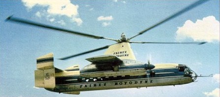
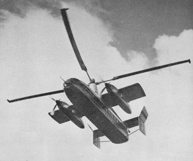
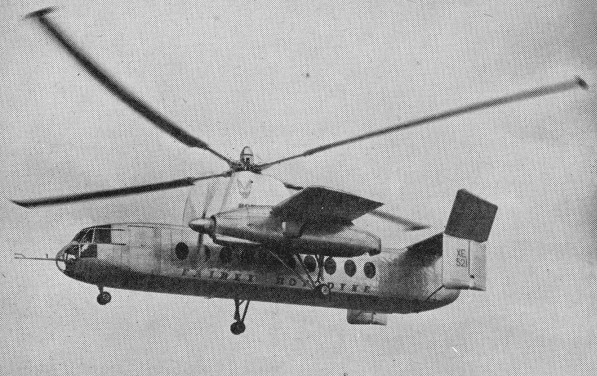
The Rotodyne was a square-section fuselage with untapered 14.17m stub wings on which were mounted two 3000shp Napier Eland turboprops for forward propulsion. The main wheels of the tricycle landing gear retracted forwards into the nacelles, and the nosewheel forwards below the cockpit. Twin fins and rudders, later joined by a central fin, were mounted on an untapered tailplane set on top of the rear fuselage. A large four-bladed rotor for vertical take-off and landing was driven by tip jets which received compressed air from the Eland engines via a compressor. To provide compressed air for the jets the two 2,800shp Napier Eland N.E1.7s operated as dual-purpose powerplants – acting either as normal propeller-turbines or as pressure-generators according to requirements. They were virtually normal Elands up to the rear of the turbine casing, where there was a nine-stage axial compressor driven by the power turbine through an hydraulic clutch. For take-off and landing most of the engine power was absorbed by the compressor, which delivered air to the internal duct system of the rotor. The small amount of remaining power of the engines went to the propellers for yaw control. In cruising flight all the power went to the propellers, with the rotor autorotating. Each engine fed air to two opposing blades so that, in the case of failure of one engine, there would be adequate pressure to keep two jets burning efficiently and giving maximum thrust.
All the earlier flying was completed with the fixed undercarriage while a revised form of retractable undercarriage, with special dampers, was designed and manufactured. This was fitted to the prototype soon after mid-year 1958 when the initial transition trials had been completed and the Rotodyne was being flown faster and for longer periods in the ‘winged autogyro’ mode.
Following the resonance and running tests, the first untethered flight of the Rotodyne, XE521 (F.9429), was made by W. R. Gellatly and J. G. P. Morton at White Waltham on 6 November, 1957, and two further flights, carrying a flight observer, were made on the first day. Originally it had been intended to keep within the ground cushion during the early flights, but the prototype was taken on a circuit of the aerodrome, well above cushion height, on one of the first three flights which were made at a weight close to the 15,000kg maximum.
Until 10 April, 1958, all flights were made in the helicopter mode. On that day, at 1220m, the first transitions were made to and from the autogyro mode and thereafter a stage-by-stage transition technique was further evolved to ensure complete safety at all moments during the manoeuvres. During the 70 earlier helicopter flights, speed had been built up to 250km/h and altitude to 2072m before transition tests were started.
In its original form the control system followed that of the Jet Gyrodyne, with direct roll and fore-and-aft control through the cyclic pitch-change of the rotor-blades; with a trimming ‘elevator’ used to select fuselage attitude (and consequently wing lift) in cruising flight; and with yaw control by differential propeller-pitch at low speeds or when hovering, and by rudders at higher cruise speeds. Early in the test programme it was found that the fore-and-aft attitude control, using the separate functions of cyclic rotor-control and elevator trim, produced some difficulties. The solution was to link the elevator to the longitudinal cyclic control for both slow and high-speed flight and to disconnect the cyclic control when cruising.
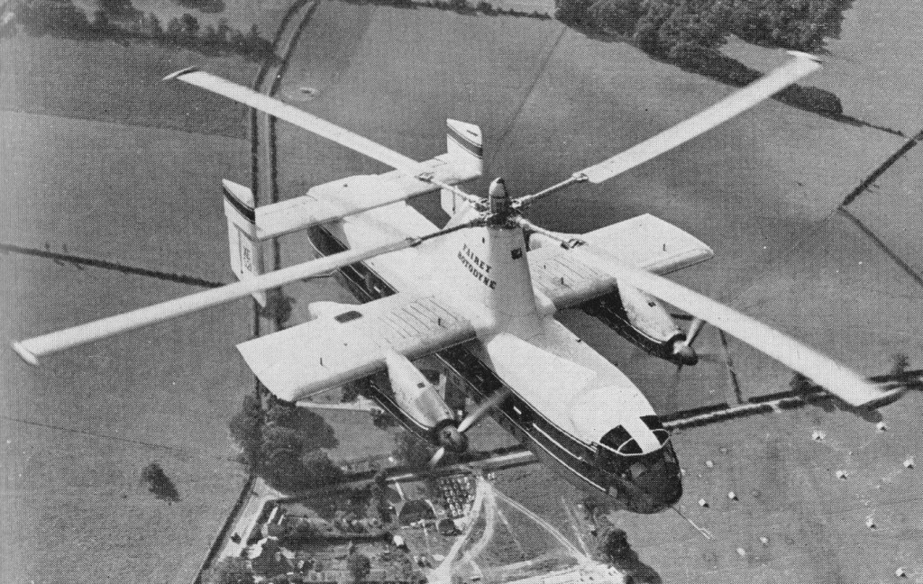
Later, when it was found that the economical cruising speed was more like 273km/h than the originally planned 209km/h, it was found that, at higher speeds, the wing was doing too much work and the rotor too little, so that the blades were flapping and the control margins were inadequate. The wing, originally set at an incidence of 4°, was re-set at 0° and fitted with ailerons, the operation of which was linked directly to the cyclic lateral control of the rotor. The outward-sloping upper fins were also moved to the vertical so as to reduce the rolling tendency with yaw. These changes produced a normal ‘aeroplane-type’ rolling control for the pilot, and the situation was further improved later by the fitting of a third upper fin.
Towards the end of 1958 a decision was made to establish a speed record with the Rotodyne. The 100km closed-circuit category was considered to be the most usefully representative of the kind of operation for which the Rotodyne was designed and that in the new convertiplane class (E.2) was chosen. On 5 January, 1959, the Rotodyne was flown by Gellatly and Morton, with Dr D. B. Leason, Fairey powerplant flight observer, and E. J. Blackburn, strain-gauge operator, as ‘passengers’, over a measured circuit between White Waltham and Hungerford, Berkshire. The flight was completed at an average speed of 307km/h – which was 79km/h higher than the equivalent record for a helicopter and nearly 48km/h higher than that for absolute speed in a straight line. At that time the Rotodyne had not yet been modified with the reduced wing-incidence and the fitting of ailerons to improve control at higher speeds. The record, which was confirmed in March, stood until October 1961, when it was beaten by the Russian twin-rotor Kamov Ka-22 Vintokryl convertiplane.
On 16 June, 1959, the Rotodyne was taken outside the United Kingdom for the first time when it was flown to Paris for the 23rd Aeronautical Salon from London’s Heathrow Airport, via the Allee Verte heliport at Brussels and the Issy heliport in Paris before landing at Le Bourget. After demonstrations there, and at Versailles for officers of the North Atlantic Treaty Organization, the Rotodyne was flown back to Heathrow.
During 1959 the wings were given ailerons and increased incidence, and the vertical tail surfaces were also revised. On 7 February 1960, XE521 resumed trials with an added central fin, shortened exhausts and a fully-faired rotor pylon.
Budgetary problems of the time saw the RAF and British Army withdraw their interest and the Rotodyne became a wholly civil project.
During 1958 the Kaman Aircraft Corporation secured a licensing agreement for sales and service in the USA with a possibility of manufacture there. Okanagan Helicopters of Vancouver was interested in three and Japan Air Lines was considering the type for domestic routes. However, the biggest potential customer was New York Airways, which joined with Kaman in a letter of intent for five, plus options on 10, for delivery in 1964. The provisional order from NYA was for the bigger-capacity, 54/65-seat Rotodyne powered with Rolls-Royce Tyne propeller-turbines and with a gross weight of 22680kg. There had been earlier references to the use of Tynes in the production version, but this order led to the first fuller statements about this version, for the development of which an additional GBP8-10 million was needed. The Government had offered to contribute half this sum, up to a certain fixed maximum, with repayment through a sales levy, but this was conditional on a firm order from BEA. Confirmation of the NYA order depended on several factors — including one that the first ‘Mk.2’ Rotodyne should be flying on test by the autumn of 1961 and another that the noise-level should be acceptable to the airline and airport authorities.
At the Paris Salon in June 1959 a model of the production version had been exhibited in the markings of New York Airways.
Fairey needed up to GBP 10 million to develop this version and was offered 50% of this by the government if BEA would place a firm order. The government contribution was to be a loan, repayable by a sales levy. In 1960 Fairey merged with Westland and although initially the Rotodyne project looked secure, it was not. In April 1960 Okanagan cancelled its order because of the long delivery dates, and five months later New York Airways expressed concern over the delay in production plans. Westland was then involved in taking over Bristol’s helicopter programme as well as with other work in hand. This, together with the ever-increasing weight of the Rotodyne, which reached a stage where the Eland could no longer be developed and the Tyne could not be afforded, led to withdrawal of government support, and the project was cancelled on 26 February 1962. On that date the British Minister of Aviation, Mr Peter Thorneycroft, said that, because of the costs involved, it was necessary to ‘forego the operational advantages’ offered by the military version, and that British European Airways, then its only potential British civil operator, had regretfully concluded that ‘the commercial prospects on their routes were not sufficiently assured to justify the heavy liabilities involved’ in placing a production order. In the absence of any firm order, Westland Aircraft did not feel justified in proceeding with the project. GBP11 million was spent during the nine years or so following the placing of the original research contract in July 1953. During the final three years of the period, however, financial support had been uncertain and the project suffered from continuing political and other indecisions which made costly forward planning impossible. The Rotodyne was subjected to a vigorous flight test program of over 350 flights, more than half of them demonstrating 200 hover-to-vertical flight transitions.
The original Fokker F-27 Friendship was built in Holland. Fairchild has built the F-27 under license from Fokker since 1958. The first F-27 models had a maximum gross weight of 40,500 pounds and seated 44 passengers. Power was supplied by twin 1,720 shp Dart turboprops. When Fairchild merged with Hiller Aircraft, the designation of the airplane was changed to FH-227 and the fuselage was stretched by six feet, giving increased cabin space for passengers and freight. The stretched airliner will accommodate up to 52 passengers. In 1960, power was increased to 2,105 shp. The stretched version was fitted with 2,250 shp engines, and ultimately the FH-227 received a redesigned windshield, stronger landing gear, strengthened rear fuselage, heavier wing skin, propellers of increased diameter and a more powerful 2,300 shp Dart turboprop. Fairchild discontinued building the FH-227 under license from Fokker in 1975.
Engines; 2 x Rolls-Royce RDa-7 Dart Mk.532, 1655kW / 2,300 shp Wingspan; 29.0 m / 95 ft 2 in Length; 25.5 m / 83 ft 8 in Height; 8.4 m / 27 ft 7 in Wing area; 70.0 sq.m / 753.47 sq ft Take-off weight; 20640 kg / 45504 lb Empty weight; 12478 kg / 27509 lb Fuel capacity: 1,364 lb Max. Speed; 483 km/h / 300 mph Top cruise: 270 mph Stall speed: 87 mph Initial climb rate: 1,560 fpm Service ceiling: 28,000 ft Takeoff run: 3,950 ft Landing roll: 4,100 ft Range w/max.fuel; 2500 km / 1553 miles Range w/max.payload; 800 km / 497 miles Seats: 44-52 Crew; 2-3
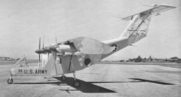
Another deflected slipstream type, similar in principle to the Ryan VZ 3, the Fairchild M 224 achieved less success. It was a two seat high-wing monoplane with a single 1,024 hp General Electric YT58 GE 2 turboshaft engine driving four propellers each of 8 ft 5 in diameter. The wing had 50 per cent chord flaps and endplates. For vertical take off, it was intended to operate at a ground angle of 30 degrees. Control in the hover was by means of small tail fans above the T tailplane for pitch and yaw, and by differential pitch on the outer propellers for roll. Tethered trials with the VZ 5 (56 6940) began on November 18th, 1959, but no free flights were made.
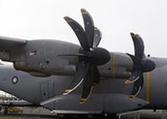
The Europrop International TP400-D6 is an 11,000 shp (8,203 kW) powerplant for the Airbus A400M military transport aircraft, developed and produced by Europrop International. It supersedes the now defunct Aero Propulsion Alliance TP400-D1 M88 derivative proposed earlier. It is the third most powerful turboprop after the contra-rotating Kuznetsov NK-12 and Progress D-27, making the TP400 the most powerful single-rotation turboprop.
The engine has a twin-spool gas generator, with a third coaxial shaft connecting the low pressure power turbine to the 5.3 m diameter, eight bladed, composite propeller, via an offset reduction gearbox. Gas generator configuration is as follows: Five-stage intermediate pressure (IP) compressor, driven by a single-stage IP turbine; contra-rotating six-stage high pressure (HP) compressor driven by a single-stage, air-cooled, HP turbine.
A three shaft configuration (i.e. 2 spool gas generator) was chosen to maximize overall pressure ratio, whilst retaining a free power turbine. An earlier proposal, designated the TP400-D1, based on the core size of the SNECMA M88-2 military turbofan was considered by Airbus to be too heavy and not sufficiently fuel efficient, so an all-new, smaller, core was chosen for the -D4.
Maximum power output is 11,000 shp installed, with an Overall Pressure Ratio of about 25:1 and a Rotor Inlet Temperature of roughly 1,500 K. With Gearbox, output can be up to 100 kNm (6840 Ft-Lb) of torque. The IP compressor has a pressure ratio of 3.5, whereas the HP compressor develops a pressure ratio of about 7.2.
The engine first ran on 28 October 2005 using a water brake as the load. During subsequent testing, the engine reached full power. On 28 February 2006 the engine was tested for the first time with the propeller installed.
Certification was scheduled for October 2007, with the A400M first flight scheduled shortly afterwards. However continued technical problems have delayed the certification test program and pushed the entire A400M aircraft program into further delays. Two milestones were reached in June 2008: its first ground run on a flight testbed, and completing integration with the first production aircraft.
The engine delays were primarily due to problems with completing the FADEC software to the satisfaction of the civil authorities. Flight trials of a single TP400-D6 engine, mounted on the port wing of a C130K flying test bed, were completed only on 30 September 2009. On 11 December 2009, the maiden flight of the A400M took place.
TP400-D6 Type: Turboprop Length: 138 in (3.5 m) Diameter: 36.4 in (0.92 m) Dry weight: 1,890 kilograms (4,167 lb) Compressor: Five stage intermediate pressure unit, with no variable stators and a six stage high pressure unit with two rows of variables Turbine: Single stage high pressure and intermediate pressure units, three stage power turbine Maximum power output: 11,000 horsepower (8,203 kW) Overall pressure ratio: 25 Turbine inlet temperature: 1500K approx Specific fuel consumption: 0.39 lb/shp-hr (0.238 kg/kW-hr) approx Power-to-weight ratio: 4.41 kW/kg (2.68 hp/lb)
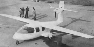
An eight place, high wing, fiberglass am¬phibious single with a 400 hp Allison 250 turbo¬prop mounted near the top of the vertical stabilizer. Intended to be amphibious, the main gear retracts into sponsons that stabilise the hull on water.
Epic Aircraft completed the successful maiden flight of its first conforming prototype E1000 single-engine turboprop, code-named FT1, putting the manufacturer on track to achieve certification later in 2016.
FT1 made its successful first flight on December 19 2015 from the Bend Municipal Airport. After the 20-minute test hop, Epic chief pilot David Robinson reported, “The aircraft handled extremely well and performed just as expected,” according to an Epic statement.
FT1 testing was assessing general handling qualities, operational performance, systems operations in normal mode, failure scenarios, extreme conditions and Flight Into Known Icing (FIKI) requirements.
The second and final flight test article, FT2, was scheduled to fly that spring, and will reflect as closely as possible the E1000 production aircraft, both in equipment and manufacturing process.
FT2 testing will focus on assessing interior and cabin functionality, including fuel, hydraulic, avionics, navigational and environmental systems.
Priced at $2.95 million the E1000 is powered by the single 1,200-horsepower Pratt & Whitney PT6A-67A turbine engine, giving is a top speed of better than 325 ktas, a max range of 1,650 nautical miles, climb rate over 4,000 feet per minute, ceiling of 34,000 feet, and full-fuel payload of 1,120 pounds.
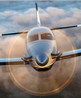
The carbon fiber Epic Escape is a pressurized single-engine turboprop that is a 92% scaled down version of the Epic LT. The pressurized, carbon-composite fuselage carrys 4-5 passengers, and the slight reduction in size allows the Escape to fly even faster than the Epic LT. The high tech airframe design with the Honeywell Garrett-10 1000 horsepower engine gives 360 KTAS. The four or five-place cabin has reclining leather seats, and exotic wood trim. The Escape VLJ turboprop was to be available as an experimental aircraft.
Seats; 4 or 5 Pressurization; 6.5 psi Engine; 1,000 hp Length; 33.4 ft. Wingspan; 36.3 ft. Height; 11.7 ft. Cabin length; 14.5 ft. Cabin width; 4.7 ft. Cabin height; 4.4 ft. Empty weight; 2,750 lbs. Maximum take-off weight; 5,500 lbs. Maximum payload with full fuel; 855 lbs. Maximum cruise; 365 KTAS Economy cruise; 300 KTAS Ceiling; 28,000 ft. Time to climb; 28,000 ft., 8 min. Range economy cruise (res / max pax); 1,800 NM
The carbon fibre Epic LT was designed and built by Rick Schameck in 14 months to 2004. The Epic Dynasty is the certified version of the Epic LT. With nearly 2000 hours logged toward certification, the Dynasty was undergoing testing mandated by Transport Canada towards Transport Canada Certification, enabling Part 135 on demand charter and air taxi services.
The Dynasty has all the features of the Epic LT, plus some extras. Available long range tanks extend the Dynasty to an estimated range of almost 1900nm. The carbon fiber fuselage paired with a PT-6 engine delivers 340 knots of true air speed. Like the Epic LT, the Dynasty carries six passengers with full fuel and baggage.
Epic LT Engine: P&W PT6-67A, 1200 hp HP range: 750-1200 Cruise: 402 mph Stall: 68 mph Range: 1840 sm Rate of climb: 4800 fpm Takeoff dist: 1500 ft Landing dist: 1500 ft Fuel capacity: 289 USG Empty weight: 4200 lb Gross weight: 7329 lb Length: 36.7 ft Wing span: 43 ft Wing area: 203.5 sq.ft Seats: 6 Landing gear: nose
Epic Dynasty Engine: Pratt & Whitney PT6-67A Wingspan: 43 ft Height: 12.5 ft Length: 35.8 ft Wing area: 203.6 sq. ft Empty weight: 4,000 lb Maximum take-off weight: 7,300 lb Usable load with standard fuel: 1,350 lb Maximum cruise: 340 KTAS Economy cruise: 288 KTAS Certified ceiling: 31,000 ft Time to climb: 9 minutes to 25,000 ft Range max cruise (w/ IFR res @ MTOW /opt LR tanks: 1,874 NM Range maximum cruise (with IFR reserves @ MTOW): 1,200 NM Take-off distance (over 50′ obstacle): 1,600 ft. Landing distance (over 50′ obstacle): 1,840 ft. Fuel capacity: 288 gallons usable Fuel capacity (optional long range tanks): 350 gallons usable Seats: 6 Cabin length: 15 ft Cabin width: 4.6 ft Cabin height: 4.9 ft Pressurization: 6.5 psi