Westland P.10 / W.34 Wyvern / W.35 Wyvern

Wyvern

Under the project designation P.10, Westland began to study early in 1944 a long-range shipboard day fighter for Naval use, with the added capability of carrying a torpedo, rockets or bombs for anti-shipping strikes. Around this proposal, Specification N. 11/44 was written, and, in November 1944, a contract was confirmed for six prototypes (including two in land-based RAF configuration to Spec F.13/44). Redesignated W.34, and subsequently named the Wyvern TF Mk 1, the Westland aircraft was a low-wing monoplane of relatively conventional layout, but larger and heavier than any previous British single-seat Naval fighter. It had upward-folding outer wing panels with hinged tips, and a 3500hp Rolls-Royce Eagle 24-cylinder liquid-cooled H-type engine driving eight-blade contraprops. Provision was made in the design for the later introduction of a turboprop engine, such as the Rolls-Royce Clyde. Basic armament comprised four 20-mm Hispano Mk V cannon in the wings, with the possibility of carrying a 46cm Mk VIII torpedo under the fuselage three 464kg bombs or eight 27kg rocket projectiles.

Westland Wyvern TF1, pre production aircraft

Only 15 aircraft were built with the Rolls Royce Eagle (2700 hp) fitted.

Westland Wyvern TF1, pre production aircraft

In August 1946, an order for 20 pre-series Wyverns with Eagle engines was confirmed, but a planned batch of 10 for the RAF was dropped, together with the F.13/44 prototypes. Subsequently, the pre-production batch was halved.

The first of six prototypes flew on 16 December 1946. However, a turboprop version with the Armstrong Siddeley Python had meanwhile been given the go-ahead and the Wyvern TF Mk 1s were assigned to various development tasks, never becoming operational. All six prototypes were flown, as were six pre-series TF Mk 1s, but the final four of the latter, although built, remained unflown as all development effort switched to the TF Mk 2.

Following the RAF’s decision to pro¬ceed no further with this project the Royal Navy opted to concentrate all future development around the Arm¬strong Siddeley Python turboprop en¬gine.

The Naval Air Staff ordered three prototypes of the (W.35) Wyvern TF Mk 2, to Specification N.12/45. Two were to be powered by the Armstrong Siddeley Python and the third by a 4500hp Rolls-Royce Clyde. In the event, the former engine was to be preferred for production aircraft. In overall configuration and armament the Wyvern TF Mk 2 closely resembled the Mk 1, although there were differences in detail, and the first flight of the Clyde-engined prototype was made on 18 January 1949, followed by the first with a Python on 22 March 1949.

Flight testing soon showed the need for modifications, noticeably to the tail unit with the progressive introduction of a larger tailplane, more fin area, dihedral on the tailplane and, eventually, finlets. Prolonged testing and development also proved necessary to achieve a satisfactory engine/propeller/throttle response system for the special demands of carrier landings, involving the two Python prototypes and most of 20 pre-series TF Mk 2s ordered in 1948 (together with a single W.38 Wyvern T Mk 3 two-seat training version).

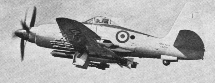
The first pre-series TF Mk 2, with a Python 2, flew on 16 February 1950, and, in June that year, became the first British turboprop aircraft to engage in carrier deck landings, aboard HMS Illustrious. Carrying a belly torpedo and 16 RPs it was a single seat strike/intruder fighter.

The final seven pre-series aircraft were completed as Wyvern S Mk 4s, this being the designation of the definitive variant with all the handling and engine modifications, and the primary mission changed to strike. The S Mk 4 was powered by a Python 3 rated at 3670hp plus 535kg residual thrust.

The principal production model was the Wyvern S.Mk 4, 94 being built in the early to mid-1950s, and these were augmented by a number of Wyvern TFMk 2 aircraft modified to Wyvern S.Mk 4 standard. Deliveries to the first FAA squadron (No 813) began during 1953. In addition, a solitary Wyvern T.Mk. 3 trainer was also completed although no production orders were forthcoming.

Westland Wyvern S.4

In September 1954, 813 embarked with their Wyverns on HMS Albion for carrier-based service in the Mediterranean. The Wyvern soon showed a worrying habit for flameout on catapult launch; the high G forces resulting in fuel starvation. A number of aircraft were lost off Albion’s bows and Lt. B. D. Macfarlane made history when he successfully ejected from under water after his aircraft had ditched on launch and been cut in two by the carrier. 813 did not return to Albion until March 1955 when the problems had been resolved.

830 Squadron was re-equipped with new aircraft before embarking in HMS Eagle on April 19, 1956. These aircraft were still designated Wyvern S.Mk4 and differed slightly in external appearance. The modifications which were visible from external inspection were:
(i) A modified cockpit canopy. This was the same shape as the previous canopy but it was a completely clear hood and did not have the metal bracing strut just aft of the pilot’s head.
(ii) The airbrake was re-designed and this can be seen from an underside view of the aircraft.
(iii) The folding wingtip facility was modded out.

Three other squadrons subsequently flew the Wyvern S Mk 4, front-line service continuing until March 1958. Operational use of the Wyvern during the Suez campaign in 1956 marked the only occasion on which British turboprop-powered aircraft saw combat use.

830 Squadron aircraft were flown ashore to Stretton and to Lee-on-Solent on January 3, 1957, and the squadron was officially disbanded from HMS Eagle in Devonport dockyard on January 5 1957.

Gallery

Wyvern TF Mk 1
Max take-off weight: 9924 kg / 21879 lb
Empty weight: 7005 kg / 15443 lb
Wingspan: 13.42 m / 44 ft 0 in
Length: 11.96 m / 39 ft 3 in
Height: 4.72 m / 16 ft 6 in
Wing area: 32.98 sq.m / 354.99 sq ft
Max. speed: 734 km/h / 456 mph
Ceiling: 9785 m / 32100 ft
Range: 1908 km / 1186 miles

Wyvern S.Mk 4
Engine: one 4,110-eshp (3065-ekW) Armstrong Siddeley Python ASP3 turboprop
Maximum speed 616 km/h (383 mph) at sea level
Service ceiling 8535 m (28,000 ft)
Range 1455 km (904 miles) with auxiliary fuel
Weight empty 7080 kg (15,608 lb)
MTOW 11113 kg (24,500 lb)
Wing span 13,41 m (44 ft 0 in)
Length 12.88 m (42 ft 3 in)
Height 4.80 (15 ft9 in)
Wing area 32.98 sq.m (355 sq ft)
Armament: four 20-mm cannon
Bombload: 1361 kg (3,000 lb)

Westland Wyvern TF Mk 1
Westland Wyvern S Mk.4

Weatherly W620 / W620TP

W620B

Built in Hollister, California and first built and certified in 1979 (TC A26WE). The 620, the first of which, N9245W, first flew in 1979 and was powered by the 450-hp R-985. The next aircraft, N9259W, was fitted with a PT6A-11AG. One similar aircraft was manufactured in 1960 but Weatherly remained faithful to the radial.

Production waned in the mid-eighties but with the introduction of the model 620A sales picked up again. The 620A wingspan was further extended another five feet to 40 ft 8 in (the wing is now 277 sq.ft) with longer ailerons and a new wingtip design but still retaining the vanes. The 620A also featured a new tail. The empty weight of the 620A is 2,840 lbs and the maximum all-up weight is 5,900 lbs, the hopper capacity being 335 US gallons.

In 1991 the 620A was upgraded to the 620B with major improvements to the cockpit and the addition of two auxiliary fuel tanks providing extra range on ferry flights. Put into production in 1992, this has by far been the most popular model with over one hundred been built and sales not only in the United States but Canada, Central and South America and Australia.

The 620B was then offered with a turbine, this time an Allied Signal TPE331-1, which Weatherly Aviation market as the 620BTG.

W620
Engine: 1 x P&W R-985, 450 hp
TBO: 1000 hrs
Prop: Hartzell, 3 blade, constant speed 95.5 in
Seats: 1
Length: 27.2 ft
Height: 8.1 ft
Wingspan: 41 ft (with wingtip vanes 47’0″)
Wing area: 264 sq.ft
Wing aspect ratio: 6.1
Max take off wt: 5600 lbs
Standard empty wt: 2760 lbs
Max useful load: 2840 lbs
Max landing wt: 4000 lbs
Wing loading: 21.2 lbs/sq.ft
Power loading: 12.4 lbs/hp
Max useable fuel: 390 lbs
Hopper capacity: 335 USG
Max climb rate: 700 fpm
Service ceiling; 15,000 ft
Max speed: 130 kts
Working speed: 78-100 kts
Stall speed flaps down: 57 kts
Turbulent air penetration speed: 122 kts
Fixed tail wheel undercarriage

W620A

W620B

W620TP
Engine: 1 x P&W PT6-11AG, 500 hp turboprop
TBO: 3500 hrs
Prop: Hartzell 3 blade constant speed 96 in
Seats: 1
Length: 30.5 ft
Height: 8.3 ft
Wingspan: 41 ft
Wing area: 264 sq.ft
Wing aspect ratio: 6.1
Max take off wt: 5600 lbs
Standard empty wt: 2700 lbs
Max useful load: 2900 lbs
Max landing wt: 4000 lbs
Wing loading: 21.2 lbs/sq.ft
Power loading: 11.2 lbs/hp
Hopper capacity: 340 USG
Service ceiling; 15,000 ft
Max speed: 153 kts
Working speed: 78-122 kts
Stall speed flaps down: 57 kts
Turbulent air penetration speed: 122 kts
Fixed tail wheel undercarriage

Walter M601

Originally the Walter turbo prop was designed for the harsh Russian environment with limited field maintenance. The engine does not require a hot section inspection, and requires only an inspection every 300 hours.
First run in 1967, the Walter M601 is a turboprop aircraft engine produced by Walter Aircraft Engines of the Czech Republic. The company’s first turboprop, the M601 is used in business, agricultural and military training aircraft.

The turboprop was designed for use on the Let L-410 and the M601 first ran in 1967. It was not suitable for the prototype L-410 and the company developed an upgraded version, the M601A, with a slightly wider diameter.

Variants:
M601A
Initial production variant for early version of the Let L410.

M601B
Production variant for the Let L410UVP.

M601D
Developed for the Let L410UVP.

M601D-1
Agricultural variant for high-cycle operation, used on the PZL Kruk and Ayres Thrush.

M601D-2
Special variant for paradrop aircraft, used on the Do 28 and some Finist conversions.

M601D-11
Agricultural and paradrop variant with a higher Time Between Overhaul of up to 1800 hours.

M601D-11NZ
Downrated variant for use in the FU-24 Fletcher.

M601E
Developed for the Let L410UVP-E.

M601E-11
General use engine with sub-variants of differing TBO.

M601E-11A
Variant of the 11 for use at higher operating altitudes and modified with a low pressure bleed air system for pressurised aircraft.

M601E-21
Variant for the L410-UVP-E used for hot and high operations.

M601F
Variant intended for use on the L420-UVP.

M601FS

M601F-11

M601F-22

M601F-32

M601FS

M601T
Aerobatic variant for use on the PZL Orlik.

M601H-80
now the GE Aviation Czech H80

M601Z
Agricultural variant for use on the Z-37T.

Applications:
Aerocomp Comp Air 10 XL
Aerocomp Comp Air 7
Ayres Thrush
Dornier Do 28
Lancair Propjet
Let Z-37T – TurboČmelák (AgroTurbo)
Let L-410 Turbolet
Let L-420
Myasishchev/SOKOL M-101T
PAC FU-24 Fletcher
Progress Rysachok
PZL-106 Kruk
PZL-130 Orlik

Specifications:
Take off rating: 690 shp / 515 kW
Prop speed: 2080 rpm
Interturbine temp: 710 deg C
Max continuous: 606 shp / 452 kW
Gas generator speed: 36,080 rpm
Prop speed: 1800-2000 rpm
Interturbine temp: 690 deg C
Max reversing rating: 413 shp / 308 kW
Weight: 420 lb / 190.5 kg

M601D-1
Type: Turboprop
Length: 1675 mm
Diameter: 590 mm
Dry weight: 197 kg
Compressor: 2-stage axial compressor and 1-stage centrifugal compressor
Combustors: annular
Turbine: 1-stage high-pressure and 1-stage free
Maximum power output: 544 kW, 490 kW continuous (740 hp, 657 hp continuous)
Turbine inlet temperature: 690°C
Specific fuel consumption: 0.62 lbs/shph
Power-to-weight ratio: 2.76:1 (kW:kg)

Vulcanair VF600W Mission

Vulcanair was the owner of the former Partenavia group and at Paris 2003 exhibited its VF600W Mission, a utility design which resembles Cessna’s Caravan. The prototype, I-VAVF, first flew in Januarv 2001 and had accumulated 30hr flying to date. Powered by a single Czech built 777shp Walter M601F 11 turboprop driving a five blad¬ed propeller, the design was aiming for cer¬tification in March 2004. This cargo/passenger aircraft has a fuselage shape which allows palletised cargo.

Engine: 1 x Walter M601 turboprop, 777 shp
Payload: 1600 kg or 11 pax
Crew: 1

Vickers Viscount

Viscount 806

The origin of the Viscount can be traced back to the war-time Brabazon Committee, which was charged with the task of steering Britain’s aircraft industry in the right direction in the immediate post-war years. One of its recommendations was the development of a turboprop-powered short/medium-range airliner (identified originally as the Brabazon IIB), and in April 1945 Vickers were instructed to proceed with its design and development, then identified by the company as the VC2 project.

Vickers Viscount Article

Discussions between the committee, liased with B.E.A., and Vickers designers resulted in the developing of the Type 609. Construction of two prototypes began in December 1946, modified to a 32-seat capacity at the request of British European Airways, renumbered Type 630 and named Viceroy. The name was changed to Viscount in 1947. This was the first of the company’s designs to be brought to fruition under the leadership of George (later Sir George) Edwards, following the death of Rex Pierson.

As finalised, a circular-section pressurised fuselage was chosen with low-set monoplane wings, a Vickers-style tail unit, retractable tricycle-type landing gear and four of Rolls-Royce’s new Dart turboprops.
Despite the efforts of Edwards, his design team and Vickers’ engineers, interest in the project waned when BEA had doubts about the aircraft’s economics in the autumn of 1947.

Prototype Model 630 Viscount (G-AHRF) powered by Rolls-Royce Darts engines was flown first on 16 July 1948. The second prototype (G-AHRG; VX217), completed with Rolls-Royce Tay turbojets was used as an engine test-bed. The design was considered as to small and slow, went back to the drawing board and re-emerged as the larger Type 700 with a 53-seat capacity. The new prototype (G-AMAV) flew for the first time on August 28, 1950. By this time, BEA had already bolstered Vickers’ enthusiasm by ordering 20 (later 26) Viscount 701s on 3 August.

Flying the Vickers Viscount

The Viscount prototype was loaded to British European Airways and operated the world’s first turboprop service on 29 July 1950. An order for 30 Viscounts was signed by BEA in August 1950 with BEA operating the first commercial flights on 18 April 1953.

A C.A.A. team arrived on May 16th 1954 to evaluate the Viscount. Their visit, the first step towards American certification of the Viscount, resulted from negotiations between Vickers-Armstrongs and TransCaribbean Airways, an American independent airline.

The Italian journal Alata reported in May 1954: “The Viscounts destined for the R.A.F., probably three in number – two to replace the present Royal Vikings – will be 700Ds, and will be powered by the new Dart RDa.6.”

The Viscount 700 had a fuselage 80 inches longer, albeit bringing a 7,500 lb weight increase. The proto-type had a fuel load of 1,620 gallons whereas pro¬duction Type 701s would carry 1,920 gallons. A total of 287 of the Viscount 700 Srs. were built.

The 800 series had more powerful engines and a longer fuselage seating up to 75 pas¬sengers and flew on 27 July 1956, sixty-seven being produced, followed by 84 Viscount 810 Srs. aircraft.

The prototype Viscount 802, G-AOJA, was the first production aircraft and destined for service with BEA. BEA had 24 Viscount on order.
The BEA Viscount 802 featured an altered instrument panel to fit a Smiths Flight System direction indicator and beam compass and Decca Flight Log.

KLM began receiving the first of nine Viscount 803s at the end of 1957. By the middle of 1958 40 airlines had ordered the Viscount 400 had been sold so far at over £150 million.

Viscount 803

One development, flown but not continued, was a RR Tay powered version.
Between 1953 and 1959 438 were sold and orders from Capital Airlines of Washington totalled 60 aircraft.

Gallery

700
Engines: 4 x 1,530 h.p. Rolls Royce Dart 506 turboprop
Length 81.2 ft. (24.75 m)
Wing span 94 ft. (28.65 m)
Weight, loaded 56,000 lb. (2,540 kg)
Seats: 3 to 4 crew; 40 to 48 passengers
Max cruise speed: 300 mph (480 kph)
Ceiling 28,500 ft. (8,700 km) fully loaded
Range: 750 miles (1,200 km) 13,000 lb payload

Viscount 700D
Engines: 4 x RR Dart 510
Span 93 ft 8.5 in
Length 81 ft 2 in
MAUW 60,000 lb
Cruise speed 320 mph

Vickers V 800 Viscount
Engines: 4 x Rolls Royce Dart 510, 1989 shp
Length : 85 ft 7 in / 26.11 m
Height : 26.739 ft / 8.15 m
Wingspan : 93 ft 8.5 in / 28.65 m
Max. speed : 297 kts / 550 km/h
Cruise speed: 315 mph
Service ceiling : 25098 ft / 7650 m
Crew : 3+60
MAUW: 62,000 lb

807
Engines: 4 x Rolls-Royce Dart

810 Viscount
Crew: 2
Passengers: 75
Engines: 4 x Rolls-Royce Dart RDa. 7/1 Mk 525 turbo-prop, 1566kW
Max take-off weight: 32885 kg / 72499 lb
Empty weight: 18854 kg / 41566 lb
Wingspan: 28.56 m / 94 ft 8 in
Length: 26.11 m / 86 ft 8 in
Height: 8.15 m / 27 ft 9 in
Cruise speed: 563 km/h / 350 mph
Ceiling: 7620 m / 25000 ft
Range w/max.payload: 2776 km / 1725 miles

Vickers Viscount

Vickers 952 / 953 Vanguard / Merchantman

In early 1953, not long after the Viscount entered service with British European Airways (BEA), discussions began to initiate the design of a successor. Both BEA and Trans-Canada Airlines were interested in a generally similar aircraft; compromise in design to satisfy the views of these two operators resulted in the low-wing configuration and ‘double-bubble’ fuselage to provide a large underfloor cargo hold beneath the main cabin.
The power plant considered originally for inclusion in the design was the Rolls-Royce Dart. But Rolls-Royce intimated that development of a new engine, the RB.109, was then well under way and it (later known as the Tyne) was chosen to power this new transport. Construction was entirely conventional except for the wing, which introduced integrally machined skins of light alloy to provide spanwise stiffening at low cost, and three shear webs instead of the single spar in the Viscount wing. When tied together by closely spaced ribs it produced a rigid box structure and outboard of the centre-section it was sealed to form integral fuel tanks.

First flight of the prototype Vanguard, as the new aircraft had been named, was made on 20 January 1959. But because of the normal development programme of a new civil airliner – coupled with delays caused by problems with the new power plant – it was not until 1 February 1961 and 1 March 1961 that these aircraft began regular service with Trans-Canada Airlines and BEA respectively. The Vanguard made its first public appearance flying London-Hamburg-London (940 sm) in 2 hr 33 min. The flight was made by the second prototype G-APEA. By then this and other second-generation turboprop-powered airliners had been deposed by the development and introduction into service of economical turbojet-powered airliners such as the Boeing Model 707. Consequently production ended after the original orders had been completed: 20 for BEA and 23 for Trans-Canada Airlines.

Trans-Canada Airlines increased its order for Vickers Vanguards to 23 during 1960.

On 10 October 1969 the first of nine freighter conversions of the Vanguard by Aviation Traders (Engineering) Ltd, called Merchantman, was flown for BEA.

Gallery

Type 952 Vanguard
Engines: 4 x Rolls-Royce Tyne RTy.11 Mk 512 turbo-prop, 4135kW / 5545 shp
Props: 4 blade, 14.5ft dia
MTOW: 146,500 lb (66451 kg)
Empty weight: 37421 kg / 82500 lb
Wingspan: 36.14 m / 118 ft 7 in
Length: 37.45 m / 122 ft 10 in
Height: 10.64 m / 35 ft 11 in
Wing area: 141.86 sq.m / 1526.97 sq ft
Cruise speed: 684 km/h / 425 mph at 20,000ft
Ceiling: 9145 m / 30000 ft
Range w/max.payload: 2945 km / 1830 miles with max payload (37000lb/16,783kg) at 420 mph
Typical range: 1830 miles (2945 km)
Crew: 2-3
Passengers: 97-139

Type 953C Merchantman

Vickers Vanguard

Vertol 76 / VZ-2

Vertol began involvement with Tilt-Wing investigations in the 1950s with work on its company-designated Model 76 program. The research would be affirmed with a joint Army/Navy contract, signed on April 15, 1956, for a tilt wing convertiplane, defined as the VZ-2A program. The design and development contract was for $850,000.

This VTOL configuration had not previously been tested in flight and the object of the programme was to build a test bed as quickly and as simply as possible. This was achieved by using available parts for several components – ¬a Bell helicopter canopy, wing actuators from the Piasecki XH 16, Piasecki HUP helicopter tail oleo struts as main undercarriage legs on the test bed and a number of parts from the Piasecki H 21. The Vertol Model 76, as the VZ 2 was known, was ready for flight in less than a year from the contract being placed.

The principal advantage of the tilt wing type of convertiplane is that it can be in most respects a conventional aircraft for cruising flight and therefore has good performance. In this respect it is similar to the tilting rotor type such as the Bell XV 3, there being some advantage in having the rotor/propeller assembly solid with the wing and tilting the whole component.

The vehicle, with much of the fuselage being of open-tubular construction, had a cockpit located far forward of the wing pivot point and featuring side-by-side seating for the two-man crew.

There were dual controls which could move control surfaces on the vertical stabilizer topped with a flat horizontal “T” configuration. The complexity of the concept was increased with the addition of a pair of ducted fans for pitch and yaw control, both being located in the tail.

A 660 horsepower Lycoming YT53-L-1 turboshaft was mounted by struts above the fuselage. The exhaust was vented outward to the left side of the rear stabilizer. Since the propellers were not attached to actual engines, the units that transferred the power from the fuselage-mounted engine resulted in considerably smaller wing units.
A portion of the turbine power was also transmitted through shafting to two ducted fans, one in the vertical and the other in the horizontal stabilizer. These fans, through a pitch-changing mechanism, were used for pitch and yaw control of the craft during hovering and transition flight.

Through a complex system which incorporated a cross shaft arrangement, the power was transferred to the pair of wing-mounted rotors which were located close to the center point of each wing. The rotors were large in diameter, at nine and one-half feet in span, and each carried three blades. The variable-pitch rotors, in addition to their primary power requirement, also provided supplemental roll control.

The craft proved to be extremely maneuverable, but was extremely slow with a maximum speed of only 215km/h. For safety purposes, the propellers were interconnected.

For aerodynamic reasons, the rear fuselage of the plane would later be skinned for smoother air flow.

Vertol test pilot Leonard La Vassar made the first flight in the VZ 2 (single example produced 56 6943) on April 13th, 1957, with the wings fixed for vertical flight. On January 7th, 1958, he made the first flight with wings horizontal and then set about ‘closing the gap’ to achieve a full transition in flight. This he did on July 15th, 1958.

Between then and September 23rd, 1959, Vertol completed 30 hours’ flying and then delivered the VZ 2 to N.A.S.A. at Langley Research Center. The first stage of N.A.S.A. testing involved another 20 hours’ flying in the next year. In this period, several modifications were introduced. A Martin Baker ejection seat was fitted changing the contours of the cockpit the rear fuselage was covered in and additional dorsal and ventral fin area was fitted.

N.A.S.A. also fitted a droop snoot leading edge to the wing. This was designed to delay the stall of the wing, which occurred initially at an incidence of 25 30 degrees, causing buffeting and control difficulties. In May 1961, Vertol was granted a new contract covering further modifications, including fitting of trailing edge flaps on the wing, which was originally flapless. With flaps, the aircraft has some characteristics of the deflected slipstream types and the stalling characteristics of the wing are further improved.

Another modification in the 1961 programme was to increase the rating of the Lycoming to 700 h.p. After testing by Vertol, the VZ 2A was returned to Langley Field. At the time the contract was placed, 448 flights had been made in the 50 hours, and 34 full and 239 partial conversions had been made.

Upon its retirement, the VZ-2A was given a place at the Smithsonian Institution.

Gallery

VZ-2A
Engine: Lycoming YT-53-L-1, 630kW / 860-shp
Rotor diameter: 2.90m
Wingspan: 7.60m
Fuselage length: 8.2m
Height: 3.15m
Take-off weight: 1443kg
Empty weight: 1128kg