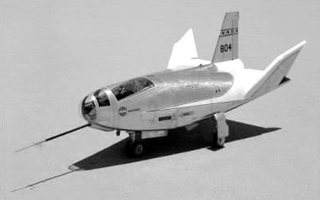
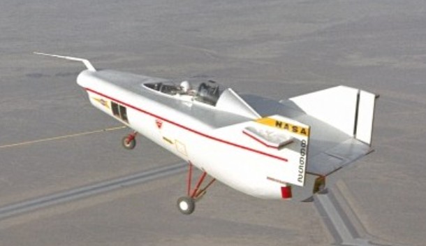
The USA also put considerable effort into the creation of lifting-body vehicles as the design precursors of manned re¬entry vehicles. These lifting-body vehicles were intended to prove the viability of wingless flying machines that could re-enter the atmosphere at hypersonic speed after orbital flight and fly back to their bases. The two main protagonists of such vehicles were Martin Marietta and Northrop, the former with the X-24, and the latter with the M2-F2 and HL-10. In mid-1964 the US National Aeronautics and Space Administration (NASA) contracted Northrop to produce the M2-F2 and HL-10. The HL-10 was similar to the M2-F2 in most respects other than the camber of its D-section lifting body. On the M2-F2 the flat and curved surfaces were on the top and bottom respectively, but on the HL-10 these positions were reversed.
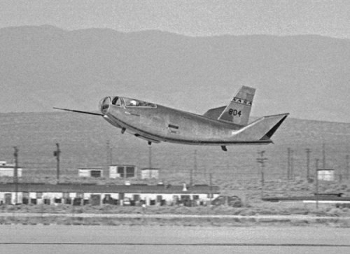
The HL-10, powered by the XLR-11 rocket engine, was dropped from beneath the wing of a Boeing B-52 on 22 December 1966. The first powered flight using rockets was made by the HL-10 from a B-52 on 13 November 1968.
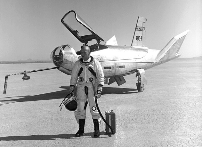
Major Jerauld Gentry standing in front of the HL-10
Engine: Thiokol (Reaction Motors) liquid-propellant rocket, 8,000 lb (3,630 kg) st Max width: 15 ft 1 in (4.60 m) between fin tips Length: 22 ft 2 in (6.76 m) Planform area: 162 sq ft (15.05 sq.m) Max launching wt: 9,400 lb (4,265 kg) Max landing wt: 8,000 lb (3,630 kg) Crew: 1 Max speed achieved: Mach 1.9 Max altitude achieved: 27430m
In mid-1964 Northrop was contracted by the US National Aeronautics and Space Administration (NASA) to produce two all-metal wingless lifting-body re-entry research vehicles, based on experience gained with the Northrop M2-F1 wooden glider, which made more than 500 flights in 1963-64. These lifting-body vehicles were intended to prove the viability of wingless flying machines that could re-enter the atmosphere at hypersonic speed after orbital flight and fly back to their bases.
The two new vehicles were designated M2-F2 and HL-10 and differed in under- and upper-surface fuselage shapes. First flight of the M2-F2 as a glider was made on 12 July 1966 when it was dropped from beneath the wing of a Boeing B-52 at 14235m to make a successful 306km/h landing four minutes later.
Bruce A. Peterson, NASA test pilot, piloted the M2F2 on 10 May 1967 landing accident that served as the opening footage for the television show ‘The six million dollar man’.
Wreck of NASA 803, 10 May 1967
The M2-F2 was badly damaged and, subsequently rebuilt as the M2-F3 made its first powered flight on 2 June 1970, attaining Mach 0.8 at 16155m on three of its four XLR11 rocket chambers. Later in the programme it recorded a height of nearly 27430m and speed of Mach 1.7. The M2-F3 had triple rather than double vertical tail surfaces.
When testing ended in 1973 these aircraft had provided much information which was to prove invaluable for NASA’s Space Shuttle programme.
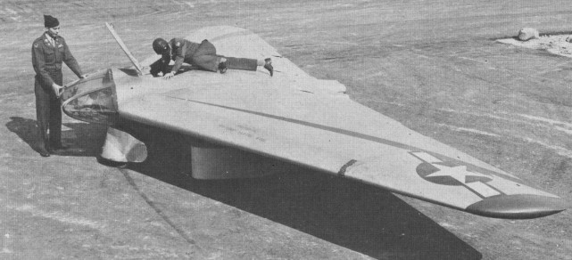
Northrop’s next flying wing project was the MX 324, planned as a research aircraft to pave the way for future flying wing fighters having jet propulsion. It was virtually a low speed glider at first, because no suitable jet power plant existed. It was also remarkably conventional, having ailerons, flaps /elevators, a minimal body and, later, a large wire braced fin. The first example had skids, and the towcar could not pull it off the ground. The second had a jettisonable trolley, which “was not a success.” The third had its own fixed tricycle landing gear, the main wheels having trousers and the nosewheel a spat. The nose leg was offset far to the left. This was because the centreline was occupied by the prone pilot, who had an interesting panel and control arrangement and rested his head in a cushioned sling inside the glass “bubble” nose. The span was about 28 feet.
Northrop went ahead with the project, under Don B Smith, in September 1942. An Army Air Force contract was awarded in January 1943 and John Myers flew the MX 324 as a glider on October 2, 1943.
By this time Northrop was talking with the infant Aerojet Engineering Corporation of Azusa, which had been formed to advance American rocketry. Their first engine planned for a manned aircraft was the XCAL 200. Though the single thrust chamber had but one thrust level, a mere 200 lb, the whole installation weighed 427 lb. This included a tank of monoethylaniline fuel, a tank of red fuming nitric acid oxidant, four gas bottles to feed the propellants, the thrust chamber and a lot of hydraulic and electric control systems. Most of it was still in bits during the first half of 1944. Early in June, the aircraft was trucked to Harper Dry Lake and static-fired on June 20. On June 22 the staked down machine was fired for the full burn time of five minutes. The next day company pilot Harry Crosby taxied under the thrust of the rocket, bringing out the need for “mods”. Finally, at dawn on July 5 Crosby smoothly rose into the cool sky on tow behind a P 38 Lightning. He cast off at 8,000 feet, paused for the tug to clear and then pressed the fire trigger on his miniature control column. It went perfectly.
The MX-334 flew under power for 3 minutes 30 seconds on 22 June 1944. On July 11 Crosby dived under power at about 350 mph to very low level before zooming up almost vertically to 6,000 feet. But the MX 324 was a bit of a dead end until new propulsion systems emerged.
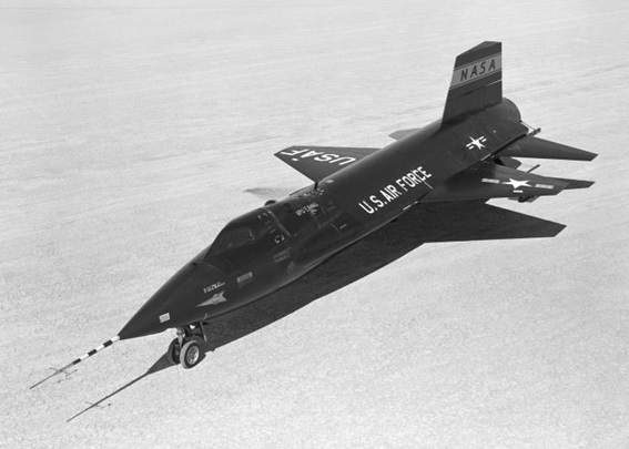
The X-15 was a hypersonic research aeroplane, a rocket-powered type air-launched by an adapted B-52 bomber within a programme that yielded important results in flight at very high speed and extreme altitudes. The objective was an aeroplane capable of flying at 4,500 mph (7,240 km/h; nearly Mach 7) and reaching an altitude of 250,000 ft (76,200 m). North American Aviation won the design contest and was awarded a development contract on 30 September 1955.
The aircraft was designated X 15 and was designed around a Thiokol (Reaction Motors) XLR99-RM-2 single-chamber throttleable XLR99 liquid-¬fuel rocket engine capable of delivering a thrust of more than 60,000 lb (27,215kg) for a period of several minutes. Like X 1, the X 15 was to be air launched, since fuel could not be expended in getting the X 15 off the ground and up to operating altitudes.
The X-15 was built largely of titanium and stainless steel, covered mostly with a so-called ‘armour skin’ of Inconel X nickel steel alloy to withstand temperatures ranging from 1200 deg F to –300 deg F, with heating rates of 30 BTU per sq ft of surface area per second. Far higher temperatures were recorded by the X-15A-2 after this type had been fitted with Emerson Electric T-500 ablative material to provide a capability for comparatively steep (and therefore high ¬friction) angles of re-entry after apogee in the interface between the troposphere and space. This capability to operate on the edges of space demanded a reaction control system for orientation of the aeroplane in these virtually airless regions: a rocket system was used for this stem, with four nozzles in the wingtips and eight more nozzles in the nose to provide three-dimensional manoeuvre capability.
Two Boeing B 52s were modified as carriers for the X 15s, three of which were ordered. With a span of only 22 ft (6.70 m) for the slightly swept¬back trapezoidal wings the X 15 had a gross weight at launch of over 31,000 lb (14,060 kg), of which more than 18,000 lb (8,165 kg) was accounted for by the liquid oxygen and anhydrous ammonia rocket propellants.
In September 1957, the first one rolled out of the factory. Six months later, in March 1959, the X-15 made its first captive flight and, three months after that, its first glide flight.
When the first X 15 free flight was made on 8 June 1959 the aircraft was fitted with lower powered engines, as the XLR99 was not then ready. Carried aloft by an NB-52, the X-15 was piloted by Scott Crossfield. With two XLR11 RM 5s, giving a combined thrust of about 33,000 lb (15,000 kg), the first powered flight was made by the second X 15 prototype (56-6671) on 17 September 1959, a speed of Mach 2.11 and altitude of 52,341 ft being achieved. From that point on, both the speed and the altitude reached by the X 15s climbed steadily, with Mach 3 being reached in November 1961 after the XLR99 engine had been fitted in the second prototype. By December 1963 the X 15s had reached a speed of Mach 6.06, had encountered a skin temperature of 1,320 degrees F and reached an altitude of 314,750 ft (95,936 m).
In June 1959, in the X-15s very first free flight, Crossfield’s landing was a little touchy due to the pitch damper failure and pilot-induced oscillation.
On 17 September 1959, Scott Crossfield took the X-15 through the paces of its first powered flight. In its second powered flight three months later, also flown by Crossfield, the vehicle’s nose gear door failed due to a rough landing on Rogers Dry Lake. According to the official report, the structural failure occurred on landing “due to design flaw and excessive propellant weight,” but the NASA engineers at Edwards knew otherwise and North American then adopted the special approach theory for landing. This involved a 360 degree spiralling descent starting at about 40,000 ft, right above the desired touchdown point on the runway. From that ‘high key’ position, the pilot moved into a 35 degree bank (usually to the left) while maintaining an airspeed of 285-345 mph. At roughly 20,000 ft after some 180 degrees of the spiral had been completed, the X-15 reached the ’low key’. At this point, the aircraft was headed in the opposite direction of the landing runway and was about four miles abeam of the touchdown point. From the low key, the turn continued through the other 180 degrees until X-15 lined up with the runway at about a five mile distance. The rate of descent through the spiral averaged over two miles per minute, which meant it took on average about three minutes to go from high key to that point where the X-15 was ready to head straight for landing.
Neil Armstrong’s second X-15 flight, and his first for research purposes, came just before noon on Friday 9 December 1960, also in the number one airplane. Flight 1-19-32 first tested the X-15’s newly installed ‘ball nose’. Until this flight, the X-15 had a front mounted boom with vanes to sense airspeed, altitude, angle of attack, and angle of sideslip in a free aerodynamic flow field. At such high altitudes and high speeds, the X-15 would melt its nose boom, destroying measurement data. The ball nose sphere could be cooled from the inside by liquid nitrogen.
Equidistant from the circumference were sensor ports in the middle of the ball as well as on the top and bottom. The ball moved automatically in pitch and yaw to keep the pressure equal on both of the ports, pointing the centre hole directly into the free flow. The angle of the ball movement amounted to the airplane’s angle of attack. Similarly, the ball nose received precise indications of angle of sideslip and dynamic pressure, which then gave airspeed.
Flight 3-4-7 piloted by Neil Armstrong on 5 April 1962, reached Mach 4.12 and 180,000 ft to test the MH96 reaction controls. The test flight spanned 181.7 miles in a little over 11 minutes before landing at Rogers Dry Lake. Flight 3-4-8, on Friday 20 April 1962, by Neil Armstrong, was to test the MH-96 system limit, or ‘g limiter’, to prevent the pilot from exceeding 5g. The flight reached 207,500 ft. Ballooning creates some control problems at the altitude and made an extended trip back. Neil Armstrong’s X-15 flight on 27 June 1962 resulted in the highest Mach number every attained in the X-15 program – Mach 5.74 or 3989 mph.
North American X-15 No.2, damaged in November 1962 in a hard landing at Mud Lake, Nevada, was completely rebuilt, ready to fly in May 1964. Most noticeable difference in X-15-2 from other models is the addition of two 22 ft fuel tanks of 38in diameter on the lower sides of the fuselage. Carrying liquid hydrogen and anhydrous ammonia, they extend burning time of the Thiokol 58,000 lb thrust YLR-99 rocket engine from 88 seconds to 146 seconds. With additional length of powered flight X-15-2 should top previous marks of 4104 mph and 354,200 ft altitude. Both set by NASA Chief Test Pilot Joe Walker.
The tanks drop off when the plane reaches Mach 2, are recoverable by parachute. Extra fuel, weighing 13,500 lb, plus other modifications, bring X-15-2’s take-off weight to 25 ton, eight ton more than the others.
The outer half of the right wing is detachable so that various structural material can be tested in flight. The plane will carry a ramjet engine slung from the tail to test hypersonic airbreathing propulsion. Liquid hydrogen ramjet fuel is stored in two internal tanks.
Cameras have been installed for ultra-violet star photography at altitude above 40 miles, beyond the ozone layer which filters out most ultra-violet rays.
The fuselage is 29in longer than other X-15’s, nose and main landing gear has been lengthened to 39.5in ground clearance, oval windshields installed to withstand higher temperatures, and ablative material added to skin surfaces to suppress heating of the basic structure.
Projects to be performed by all three X-15’s were expected to require another 100 flights running well into 1968.
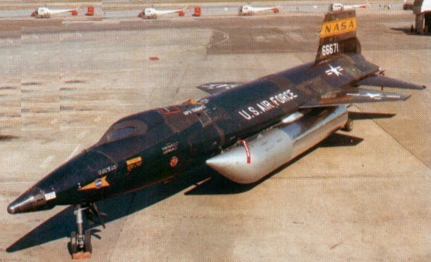
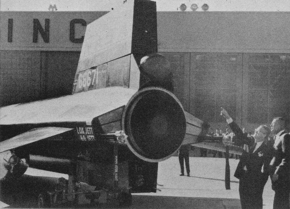
The X-15A-2 propulsion system is Thiokol Chemical’s Reaction Motors Division’s YLR99 rocket engine. Even its 58,000 lb thrust can be upped through externally-mounted ramjet engines. The YLR99 operates on liquid oxygen and anhydrous ammonia which is fed into the thrust chamber by a turbopump driven by hydrogen peroxide. The ball above the engine exhaust chamber (tail slot) will contain pressurised helium which will be used to expel liquid hydrogen fuel in testing of the ramjet engines.
X-15A-2
In an experiment in 1964, an X-15 attempted a photo mission from 100,000 ft while speeding at 3290 mph over Edwards AFB (Calif). The purpose was to determine effect on camera and film of extremely high temperatures encountered at that speed, and clarity of photos for reconnaissance use.
With Major William J. “Pete” Knight at the controls, the modified X-15A-2 set an unofficial speed record of 4,520 mph (Mach 6.70) on 3 October 1967. This would be the fastest flight of the X-15 program.
X-15A-2
Before the end of 1961, the X-15 had attained its Mach 6 design goal and flown well above 200,000 feet; by the end of 1962 the X-15 was routinely flying above 300,000 feet. The X-15 had already extended the range of winged aircraft flight speeds from Mach 3.2 to Mach 6.04, the latter achieved by Bob White on 9 November 1961.
On 9 November 1962, the second X-15 crashed while executing an emergency landing on Mud Lake near Edwards AFB. Pilot Jack McKay was seriously injured but later returned to flight status. The X-15 itself was nearly a write-off, but eventually the Air Force and NASA decided to rebuild it to a slightly different configuration. The fuselage was lengthened 29 inches and external drop tanks were added to accommodate additional propellants. It was hoped this would allow the X-15A-2 to achieve at least Mach 7 while testing experimental scramjet engines. This first flew on 28 June 1964. On 22 August 1963 Joseph A. Walker, NASA test pilot, took the o.3 X-15 for a world altitude record of 351,000 ft. It was the fifth flight into space for the plane and the third for Walker. He covered 315 miles in 10 minutes. Walker released a 30-inch balloon from the plane’s tail then towed it 100 yards behind to measure air density in space. The aircraft reached a speed of 3614 mph and a climb angle of 48 degrees, the steepest yet. It used 18,000 lb of fuel in 83 seconds. Walker and the X-15 then held the world speed record of 4104 mph for winged aircraft.
In 1965 Joe Engle flew an X-15 to 78,000 ft and 3511 mph on an 8 min flight to simulate surface heating characteristics. A sheet of brown silicon rubber glued on the lower tail was expected to reduce temperature at that point from 800deg to 400 deg F.
Using an ablative coating to provide additional heat protection, Major Pete Knight took the X-15A-2 to Mach 6.72 (4,520 mph) and an altitude of 354,200 ft / 107,960m on 3 October 1967, the fastest piloted flight of the X-Plane program. This is the highest recorded speed yet achieved by man in an aeroplane capable of being controlled in normal flight. Due to damage resulting from this flight, the aircraft was retired and subsequently transferred to the Air Force Museum.
The aircraft proved remarkably flexible as a research tool. In fact, most of the later flights used the X-15 as a carrier vehicle for other experiments rather than as a research aircraft in its own right. An assortment of experiments were carried, including micrometeorite collection pods, missile detection systems, samples of insulation destined for the Saturn launch vehicle, and a wide variety of others.
After 177 flights (some report 199), the last on 24 October 1968, the X-15 programme was terminated in 1968. Of the three X-15s manufactured, one crashed while returning from space, killing test pilot Major Michael J. Adams, and one survives in the National Air and Space Museum.
Crossfield flew the X-15 a total of 13 times before North American turned it over to NASA-Air Force-Navy partnership. Two of Crossfield’s flights were in the number one airplane, the rest in number two. The highest speed he reached in any of them was Mach 2.9, the highest altitude 88.116 ft, and the furthest distance was 114.4 miles.
The NASA and other pilots were Joe Walker, Jack McKay, Robert White USAF, Neil Armstrong USN, Cmdr Forrest Petersen USN.
Engine: 1 x Reaction Motors XLR-99 rocket engine, 253.7kN Max take-off weight: 15422 kg / 34000 lb Wingspan: 6.7 m / 22 ft 0 in Length: 15.8 m / 51 ft 10 in Height: 4.1 m / 13 ft 5 in Wing area: 18.6 sq.m / 200.21 sq ft Max. speed: 7297 km/h / 4534 mph Ceiling: 107960 m / 354200 ft Crew: 1
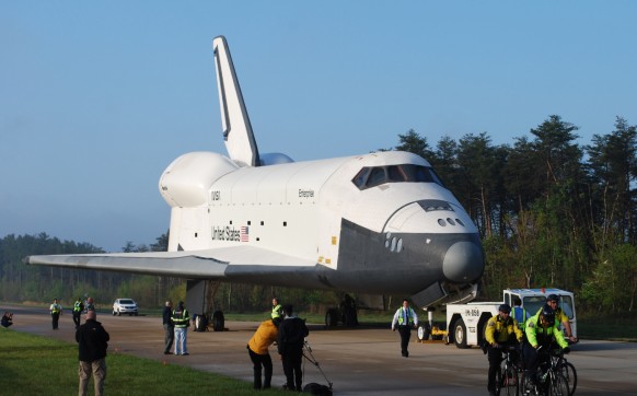
There had long been the desire to have a reusable vehicle that could be launched into Earth orbit, have the ability to manoeuvre in space, re enter Earth’s atmosphere and land conventionally on an airfield. The first step in this direction was made with lifting body research aircraft which, in turn, led to design of the Space Shuttle Orbiter, for which Rockwell International became prime contractor in July 1972.
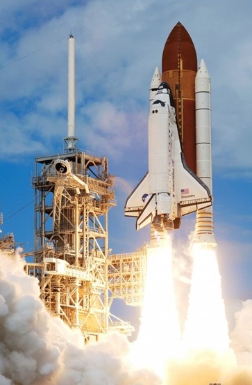
A large vehicle with a thick section wing of double delta planform, the SSO has a fuselage which conforms to lifting body outlines. Mounted in the rear fuselage are three Rocketdyne SSME rocket engines, each developing 417,300 lb (189287 kg) thrust for launch, at which time the SSO has mounted beneath it a large external fuel tank for the SSME rocket engines, and at each side of the tank a solid propellant rocket booster. The whole assembly is launched with the main engines and the boosters firing; after burn¬out the boosters are jettisoned and recovered by parachute, the main engines then being fed from the external fuel tank, which is jettisoned just before entry into orbit. Having completed its orbital mission, during which the SSO is controlled by orbit manoeuvring and reaction control engines, a de orbiting manoeuvre is initiated and, at a high angle of attack, the SSO re enters Earth’s atmosphere to make an unpowered but otherwise conventional aircraft type landing.
It was not until 13 August 1977 that the Enterprise and its crew were launched in free flight from the SCA at a height of 22,800 ft (6950 m), to make a gliding and unpowered flight to a conventional landing at Edwards AFB, California.
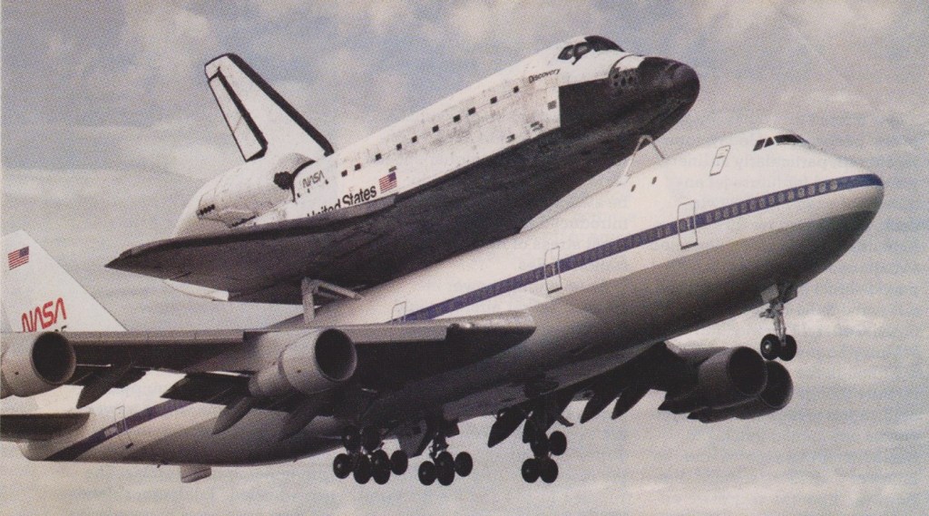
Boeing 747 123 Shuttle Carrier Aircraft (SCA) (NASA 905)
Almost four years later, on 12 April 1981, the spacecraft OV 102 Columbia, crewed by astronauts John Young and Robert Crippen, lifted off from Cape Canaveral on the first orbital mission. It then completed 37 orbits of the earth in 54 hours and on 14 April made a near perfect unpowered 200 mph (322 km/h) landing on Runway 23 at Rogers Dry Lake, Edwards AFB, California. The first ever “soft” return from space in a re-usable craft that is part spaceship and part aeroplane.
The Columbia was subsequently flown back to Cape Canaveral on the back of its Boeing 747 mother-plane for full examination and preparation for the next mission.
The Napier Scorpion was a British liquid-fuelled rocket aircraft booster engine developed and manufactured by Napier. It used hydrogen peroxide / kerosene propellant.
The first Scorpion NSc.1 was successfully flight-tested in a Canberra.
From 1956 the Double Scorpion NScD.1 was fitted experimentally to two Canberra light bombers, to improve high altitude performance. A world altitude record of 70,300 feet (21,427 m) was set by Canberra WK163 on 28 August 1957.
This was on the eve of cancellation of manned aircraft programmes by the 1957 Defence White Paper.
The Scorpion project was cancelled in February 1959, at a reported total cost of £1.25 million.
This, the first rotorcraft (1952) which Nagler designed after his arrival in the United States, was of the ‘strap-on’ variety. Its intended use was to cross rivers or other obstacles. The required height was to be reached by power from six solid-propellant rockets, fired in pairs and providing a 9kg thrust for about twenty seconds. Slow descent was ensured by the auto-rotation of the rotor. The six rockets could be replaced for later use. The wearer’s legs were to be the landing gear.
With the addition of a 2 cylinder opposed engine driving a pusher prop also in 1952, the XNH-1 was re-designated XNH-2 Heligyro.
XNH-I Heliglider Engine: 6 x 9 kg rockets Weight empty: 29.5kg / 67 b Crew: 1
In July 1944, the Imperial Navy issued a l9-Shi specification for a rocket-propelled target defence interceptor to be based on the Messcrschmitt Me 163B. The task of developing this aircraft was assigned to Mitsubishi under the Navy designation J8M1, but as it was a joint Navy-Army venture it received the designation Ki-200 from the latter service and the name Shusui (Sword Stroke) was also adopted. Development of the Messerschmitt Me 163B rocket-powered fighter in Germany prompted Japan to acquire rights to build this aircraft and its Walter rocket engine.
A complete Me 163B plus an example of the Walter HWK 109 509A engine and detailed blueprints were shipped to Japan in mid-1944 but the submarine carrying this precious cargo was sunk en route. A second submarine managed to get through but this only brought a rocket engine and an Me 163 instruction manual, no detailed plans or blueprints.
While work on the Walter HWK 109-509 rocket motor (as the Toku Ro.2) was largely confined to its adaptation for Japanese manufacturing techniques. Yokosuzka Naval Aeronautical Engineering Arsenal was given the task of constructing the eng¬ine. Mitsubishi Jukogyo KK was instructed to build the fighter though inadequate German data on the airframe dictated considerable original structural design work.
With J8M1 prototype design finalised, the 1st Naval Air Arsenal began construction of a full-scale training glider version at Yokosuka under the designation MXY8 Akigusa (Autumn Grass), and this was towed into the air and flown for the first time in December 1944.
A heavier glider, with ballast tanks to approximate the weight of the operational aircraft, was also built under the designation Ku-13 Shusui (sword stroke). Design of the rocket engine resulted in the 1500kg thrust Toko Ro.2, and this powerplant was installed in the first of the J8M1 Navy Experimental Rocket-Powered Interceptor Fighter Shusui prototypes completed by Mitsubishi.
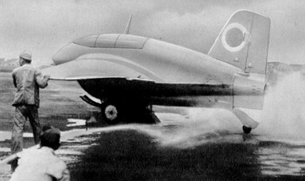
The first Shusui made an unpowered test flight on 8 January 1945. The first powered flight test took place six months later, on 7 July, but the aircraft was destroyed and no further flight testing was undertaken before the termination of hostilities. Four more Shusui interceptors had been completed by this time, and six more were virtually complete.
J8M Power Plant: One Toku Ro.2 (KR-20) bi-fuel rocket motor with a maximum thrust of 3,307 lb (1 500 kg) Endurance: 50-55 min. Fuel capacity totalled 255 Imp gal (1159 lt) of Ko-liquid and 118 Imp gal (536 lt) of Otsu-liquid Max speed, 559 mph (900 km/h) at 32,810 ft (10000 m) Time to 19,685 ft (6000 m), 2.26 min Time to 32,810 ft (10000 m), 3.5 min Time to 39,370 ft (12 000 m), 3.83 min Service ceiling, 39,370 ft (12000 m) Empty weight equipped, 3,318 lb (1 505 kg) Max loaded weight, 8,565 lb (3885 kg) Span, 31 ft 2 in (9,50m) Length, 19 ft 10 ¼ in (6,05 m) Height (on dolly), 8 ft l0 ¼ in (2,70 m) Wing area, 190.84 sq ft (17,73 sq.m) Armament: Two 30-mm Type 5 cannon with 50 rpg Crew: 1
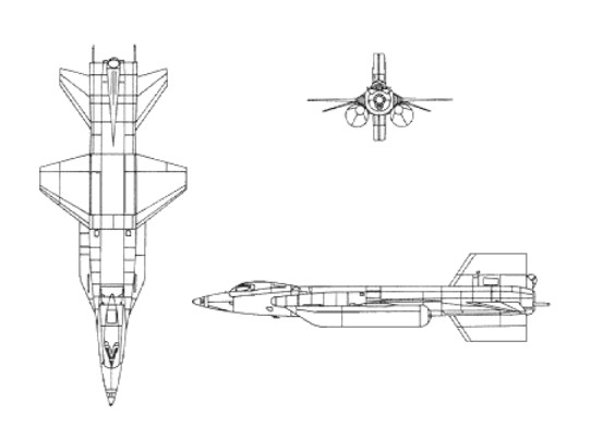
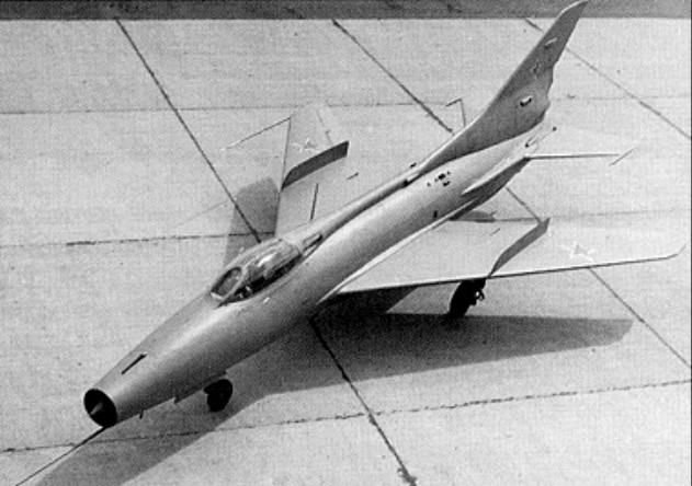
In 1953 the Soviet authorities issued a requirement for a Mach 2 clear-weather interceptor with limited ground-attack capability. At this time the USSR’s Central Aerodynamics and Hydrodynamics Institute had arrived at two basic configurations for aircraft of the required performance level. Both were based on a cylindrical fuselage with a swept all-moving tailplane and a wing in the low mid-set position, but the difference came in the wing itself. One was a conventional type with a leading-edge sweep of between 580 and 620, and other a delta with 570 or 580 leading-edge sweep. The MiG bureau produced prototypes in both configurations. The Ye-50 and Ye-4. Designed around a Tumansky AM-9Ye (RD-9Ye) turbojet with an afterburning thrust of 3800kg and a Dushkin S-155 bi-fuel rocket motor of 1300kg, the first of three prototypes, the Ye-50/1, flew on 9 January 1956. It began trials with the rocket motor on 8 June 1956.
The original Ye-50 can be regarded as a pre-prototype, for in the absence of the planned Tumanskii R-11 turbojet it was fitted with an interim composite powerplant comprising an RD-9Ye afterburning turbojet and an S-155 rocket engine; the aeroplane had swept conventional wings based on those of the MiG-19.
A year later, on 17 June 1957, the second prototype, the Ye-50/2, attained a speed of Mach=2.33 and an altitude of 25600m. The Ye-50/2 introduced some modifications to the rear fuselage and vertical tail, and the Ye-50/3 featured a lengthened fuselage nose and increased internal fuel. This last prototype was lost during flight test when its vertical tail detached. The Gor’kiy factory was ordered to build a batch of 20 aircraft, which, powered by the AM-11 engine and S-155 rocket, were to be designated Ye-50A. These were intended for operational evaluation, but none of them was built owing to a lack of rocket motors, the Dushkin OKB having meanwhile closed down.
Ye-50/1 Max take-off weight: 8500 kg / 18739 lb Wingspan: 8.11 m / 26 ft 7 in Length: 13.62 m / 44 ft 8 in Height: 21.00 m / 68 ft 11 in Max. speed: 2460 km/h / 1529 mph Ceiling: 23000 m / 75450 ft Range: 450 km / 280 miles
In February 1944, the MiG OKB initiated the design of a mixed-power single-seat fighter with the Izdeliye designation N. Conceived to use the so-called “accelerator”, or VRDK (Vozdushno-reaktivny dvigatyel kompressorny, or Air-reaction engine compressor), which had been developed at the TsIAM under the leadership of K V Kholshchevnikov, the N preliminary design was finished on 28 March 1944. Drawings were completed by 30 November 1944, by which time the official designation I-250 had been applied to the project, and three months later, on 26 February 1945, the first of two prototypes, the N-1, left the factory.
Primary power was provided by a Klimov M-107A (VK-107A) 12-cylinder Vee-type engine rated at 1650hp for take-off and armament was three 20mm G-20 cannon, one between the engine cylinder banks and the others flanking the engine. The VRDK consisted of an engine-driven compressor which fed compressed air via a water radiator to a mixing chamber in which fuel was introduced under pressure, the mixture being ignited in a double-walled combustion chamber and then ejected through a variable orifice. This provided 300kg of thrust for up to 10 minutes, boosting speed by 100km/h.
The first flight took place on 3 March 1945, and the VRDK was fired for the first time during the third test flight. N-1 crashed during mid-May when the permissible load factor was exceeded and the horizontal tail collapsed at low altitude, but a second prototype, the N-2, was rolled out on 26 May 1945. This lacked armament and the vertical tail was enlarged to rectify some longitudinal instability, but this prototype, too, was destroyed in an accident. In July 1945, the OKB received instructions to supervise the construction of 10 I-250 aircraft to participate in the Air Parade that was planned for 7 November 1945, barely four months later. Nine I-250s were ready on time, but inclement weather resulted in cancellation of the Parade. These aircraft, together with a further seven, were subsequently delivered to the Navy as MiG-13s, equipping an evaluation unit based at Skultye airfield, near Riga. Several of the pre-series MiG-13s were experimentally fitted with sabre-shaped propeller blades, and official NII VVS trials were conducted between 9 October 1947 and 8 April 1948. Production of the I-250 / MiG-13 had totalled 16 pre-series aircraft, and although the fighter was essentially successful, it had been overtaken by pure jet fighters and surviving examples were retired by the Navy in May 1948.
N-1 Engine: 1 x Klimov M-107A (VK-107A) 12-cylinder, 1650hp & 1 x VRDK, 300kg thrust Max. speed: 825 km/h / 513 mph Ceiling: 11960 m / 39250 ft Range: 1380 km / 858 miles Armament: 3 x 20mm G-20 cannon
N-2 Engine: 1 x Klimov M-107A (VK-107A) 12-cylinder, 1650hp & 1 x VRDK, 300kg thrust Max take-off weight: 3931 kg / 8666 lb Empty weight: 3028 kg / 6676 lb Wingspan: 9.50 m / 31 ft 2 in Length: 8.18 m / 26 ft 10 in Wing area: 15.00 sq.m / 161.46 sq ft