By 1952 Saunders-Roe produced the SR.53 design for a single-seat target defence interceptor combining a liquid-fuel rocket motor with an auxiliary turbojet. Submitted to the Ministry of Supply (MoS) the design based on the pairing of the de Havilland Engines DGJ.1OR Gyron junior turbojet and Spectre rocket motor, to meet the requirements of Specification F.124T. This was accepted with high regard, and Specification F.177D was written around it to meet Operational Requirement (OR) 337. Furthermore, naval requirement NR/AA7 was combined in the specification, the designation SR.177R being applied to the RAF aircraft and SR. 177N to those for the Fleet Air Arm (FAA). The SR.53 was recipient of a three-prototype contract in October 1952. Armament proposed was a Red Top missile on each wingtip.
On September 4, 1956, Saro received an initial order for nine aircraft, and West Germany expressed enough interest for the eventual figure of 600 production aircraft to be mooted. Production was to be shared among Saro and other companies, and German companies were to manufacture that nation’s variant, so the whole programme would benefit a large European workforce.
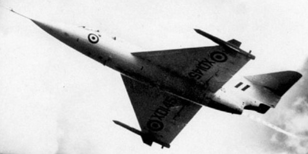
With one 8,0001b-thrust de Havilland Spectre rocket engine and one 1,6401b-thrust Armstrong Siddeley Viper turbojet. Of clipped delta wing configuration with a specified armament of two wingtip-mounted Blue Jay (de Havilland Firestreak) AAMs, the SR.53 was powered by an 3629kg de Havilland Spectre HTP rocket and a 744kg Armstrong Siddeley Viper turbojet superimposed one above the other in the rear fuselage.
In the event, only two of the SR.53s were to be completed (XD145 and XD151), these making their initial flights on 16 May and 8 December 1957, prior to which, in April 1957, all rocket-powered fighter development in the UK had been cancelled.
Duncan Sandys’ Defence the White Paper of 1957 resulted in the cancellation of the whole project. When a British request to the USA for funding under the Mutual Weapons Development Program (MWDP) was turned down, West Germany dropped out and turned to the Lockheed F-104 Starfighter.
Nonetheless, the two SR.53s performed 42 test flights before, on 15 June 1958, the second aircraft crashed, the surviving aircraft then being permanently grounded.
SR.53 Max take-off weight: 8618 kg / 19000 lb Empty weight: 3357 kg / 7401 lb Wingspan: 7.65 m / 25 ft 1 in Length: 13.72 m / 45 ft 0 in Height: 3.29 m / 11 ft 10 in Wing area: 25.45 sq.m / 273.94 sq ft Max. speed: 2135 km/h / 1327 mph
The six passenger SpaceShipTwo is carried aloft by WhiteKnightTwo.
Virgin Galactic’s SpaceShipTwo made its second successful powered flight on 5 September 2013 from Mojave Air and Space Port in California.
SpaceShipTwo, funded by billionaire Richard Branson, was carried to an altitude of 42,000 feet attached to the “mothership” and then climbed to 69,000 feet under its own power before descending back to Mojave.
“In addition to achieving the highest altitude and greatest speed to date, the test flight demonstrated the vehicle’s full technical mission profile in a single flight for the first time … All of the test objectives were successfully completed,” the company said.
Burt Rutan leads one of 27 teams from seven countries competing for the US$10 million (NZ$16 million) X Prize, to be given to the first private entrepreneur who can put three people into sub-orbital space and do it again with the same equipment within two weeks by the end of 2004.
The team is funded by Microsoft co founder Paul Allen.
SpaceShipOne will piggyback aboard a mother aircraft known as the White Knight, to an altitude of 48,000 feet (14,600 metres). On release, SpaceShipOne’s 18,000 lb thrust rocket engine burns for 80 seconds, accelerating the aircraft at three times the force of gravity to reach Mach 3.2 (3860kph) by the time the engine burns out at 160,000 ft (48,700m). Coasting the rest of the way, losing power and slowing down. At 200,000ft, the pilot and passengers in the future experience weightlessness, which lasts three to four minutes as the spacecraft attains its maximum altitude of 340,000ft, virtually stops, then falls back to 200,000ft (60,000m), when it begins to feel the atmosphere once again. The key is to decelerate gently in the upper atmosphere by controlling the angle during descent and maximising drag, making for a much safer and more comfortable ride.
SpaceShipOne, the rocket plane funded by Microsoft cofounder Paul G Allen, appeared to top its required altitude within minutes of firing its rockets in 2004. The plane took, off from a desert runway slung to the belly of a carrier plane with a test pilot at the controls. It was released at about 13,800m and fired its rockets to climb to an altitude of 100km.
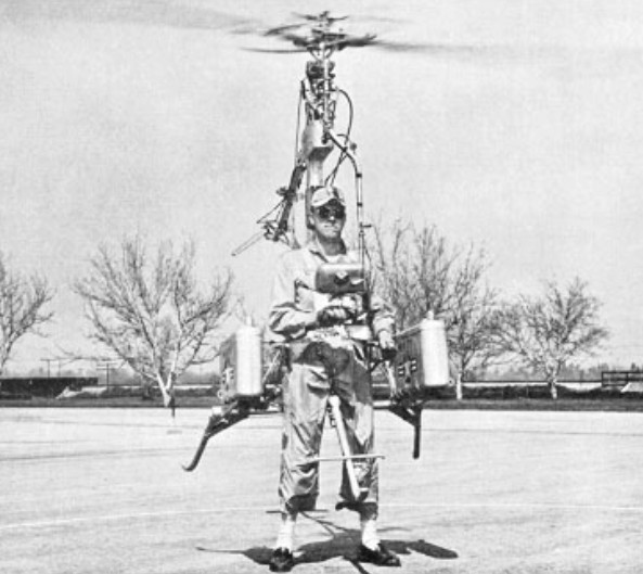
Little more heard of Gilbert Magill until the mid-1950s, when the RH-1 Pinwheel ‘strap-on’ personal helicopter appeared in 1954. The Rotorcraft RF-1 Pinwheel one-man helicopter was designed in 1954 to provide military personnel with a simple go-anywhere vehicle. Basically a strap-on device, it relied upon liquid propellants to power a tipjet at the end of each rotor blade, there thus being no rotor torque effect. The Pinwheel had a ‘quadripod’ frame layout, with the pilot sitting in the centre of the structure with a pair of liquid nitrogen tanks positioned behind him to feed Reaction Motors XLR-32RM rocket motors mounted at the rotor tips. A belt-driven rail rotor was incorporated in the simple and limited structure to provide steering capability.
Designed and built under US Navy contract, the RH-1 was extensively tested and made public demonstrations in 1955, leading to development of a similar Sky Hook military version. The capability of the Pinwheel can be measured by a maximum speed of 161km/h and ceiling of 4570m.
The Rocketdyne AR-2 is fitted above and aft of the J79 engine in the Lockheed NF-104A. To attain a 25 mile altitude the 6000 lb thrust engine burns a mixture of JP-4 jet fuel and hydrogen peroxide.
The AR-2 is throttleable from 50 to 100% power. The NF-104A provides spaceflight experience at a fraction of X-15 operating costs.
The RS-25, otherwise known as the Space Shuttle Main Engine (SSME), is a liquid-fuel cryogenic rocket engine that was used on NASA’s Space Shuttle. Built in the United States by Rocketdyne, the RS-25 burns cryogenic liquid hydrogen & liquid oxygen propellants, with each engine producing 1,859 kN (418,000 lbf) of thrust at liftoff. Although the RS-25 can trace its heritage back to the 1960s, concerted development of the engine began in the 1970s, with the first flight, STS-1, occurring on April 12, 1981. The RS-25 has undergone several upgrades over its operational history to improve the engine’s reliability, safety and maintenance load.
The engine produces a specific impulse (Isp) of 453 seconds (4.44 km/s) in a vacuum, or 363 seconds (3.56 km/s) at sea level, consumes 1,340 L (350 US gal) of propellant per second, has a mass of approximately 3.5 tonnes (7,700 pounds) and is capable of throttling between 67% and 111% of its rated power level in one-percent increments. The RS-25 operates at extreme temperatures, with the liquid hydrogen fuel being stored at −250 °C (−418 °F) while the temperature in the combustion chamber reaches 3,315 °C (6,000 °F), higher than the boiling point of iron.
On the Space Shuttle, the RS-25 was used in clusters of three engines mounted in the aft structure of the Orbiter, with fuel being drawn from the external tank. The engines were used for propulsion during the entirety of the spacecraft’s ascent, with additional thrust being provided by two solid rocket boosters and the orbiter’s two AJ-10-190 Orbital Maneuvering System engines. Following each flight, the engines were removed from the orbiter, inspected and refurbished before being reused on another mission.
The RS-25 engine consists of various pumps, valves and other components which work in concert to produce thrust. Fuel (liquid hydrogen) and oxidizer (liquid oxygen) from the Space Shuttle external tank entered the orbiter at the umbilical disconnect valves, and from there flowed through the orbiter’s main propulsion system (MPS) feed lines; whereas in the Space Launch System (SLS), fuel and oxidizer from the rocket’s core stage will flow directly into the MPS lines. Once in the MPS lines, the fuel and oxidizer each branch out into separate paths to each engine (three on the Space Shuttle, up to five on the SLS). In each branch, prevalves then allow the propellants to enter the engine.
Once in the engine, the propellants flow through low-pressure fuel and oxidizer turbopumps (LPFTP and LPOTP), and from there into high-pressure turbopumps (HPFTP and HPOTP). From these HPTPs the propellants take different routes through the engine. The oxidizer is split into four separate paths: to the oxidizer heat exchanger, which then splits into the oxidizer tank pressurization and pogo suppression systems; to the low pressure oxidiser turbopump (LPOTP); to the high pressure oxidizer preburner, from which it is split into the HPFTP turbine and HPOTP before being reunited in the hot gas manifold and sent on to the main combustion chamber (MCC); or directly into the main combustion chamber (MCC) injectors.
Meanwhile, fuel flows through the main fuel valve into regenerative cooling systems for the nozzle and MCC, or through the chamber coolant valve. Fuel passing through the MCC cooling system then passes back through the LPFTP turbine before being routed either to the fuel tank pressurization system or to the hot gas manifold cooling system (from where it passes into the MCC). Fuel in the nozzle cooling and chamber coolant valve systems is then sent via preburners into the HPFTP turbine and HPOTP before being reunited again in the hot gas manifold, from where it passes into the MCC injectors. Once in the injectors, the propellants are mixed and injected into the main combustion chamber where they are ignited. The burning propellant mixture is then ejected through the throat and bell of the engine’s nozzle, the pressure of which creates the thrust.
The Low Pressure Oxidizer Turbopump (LPOTP) is an axial-flow pump driven by a six-stage turbine powered by liquid oxygen which operates at approximately 5,150 rpm. It boosts the liquid oxygen’s pressure from 0.7 to 2.9 MPa (100 to 420 psi), with the flow from the LPOTP then being supplied to the high-pressure oxidizer turbopump (HPOTP). During engine operation, the pressure boost permits the high-pressure oxidizer turbine to operate at high speeds without cavitating. The LPOTP, which measures approximately 450 by 450 mm (18 by 18 in), is connected to the vehicle propellant ducting and supported in a fixed position by being mounted on the launch vehicle’s structure.
The HPOTP consists of two single-stage centrifugal pumps (a main pump and a preburner pump) mounted on a common shaft and driven by a two-stage, hot-gas turbine. The main pump boosts the liquid oxygen’s pressure from 2.9 to 30 MPa (420 to 4,400 psi) while operating at approximately 28,120 rpm, giving a power output of 23,260 hp. The HPOTP discharge flow splits into several paths, one of which drives the LPOTP turbine. Another path is to, and through, the main oxidizer valve and enters the main combustion chamber. Another small flow path is tapped off and sent to the oxidizer heat exchanger. The liquid oxygen flows through an anti-flood valve that prevents it from entering the heat exchanger until sufficient heat is present for the heat exchanger to utilize the heat contained in the gases discharged from the HPOTP turbine, converting the liquid oxygen to gas. The gas is sent to a manifold and then routed to pressurize the liquid oxygen tank. Another path enters the HPOTP second-stage preburner pump to boost the liquid oxygen’s pressure from 30 to 51 MPa (4,300 psia to 7,400 psia). It passes through the oxidizer preburner oxidizer valve into the oxidizer preburner, and through the fuel preburner oxidizer valve into the fuel preburner. The HPOTP measures approximately 600 by 900 mm (24 by 35 in). It is attached by flanges to the hot-gas manifold.
The HPOTP turbine and HPOTP pumps are mounted on a common shaft. Mixing of the fuel-rich hot gases in the turbine section and the liquid oxygen in the main pump can create a hazard and, to prevent this, the two sections are separated by a cavity that is continuously purged by the engine’s helium supply during engine operation. Two seals minimize leakage into the cavity; one seal is located between the turbine section and the cavity, while the other is between the pump section and cavity. Loss of helium pressure in this cavity results in automatic engine shutdown.
The low-pressure fuel turbopump (LPFTP) is an axial-flow pump driven by a two-stage turbine powered by gaseous hydrogen. It boosts the pressure of the liquid hydrogen from 30 to 276 psia (0.2 to 1.9 MPa) and supplies it to the high-pressure fuel turbopump (HPFTP). During engine operation, the pressure boost provided by the LPFTP permits the HPFTP to operate at high speeds without cavitating. The LPFTP operates at around 16,185 rpm, and is approximately 450 by 600 mm (18 by 24 in) in size. It is connected to the vehicle propellant ducting and is supported in a fixed position by being mounted to the launch vehicle’s structure.
The HPFTP is a three-stage centrifugal pump driven by a two-stage hot-gas turbine. It boosts the pressure of the liquid hydrogen from 1.9 to 45 MPa (276 to 6,515 psia), and operates at approximately 35,360 rpm with a power of 71,140 hp. The discharge flow from the turbopump is routed to, and through, the main valve and is then split into three flow paths. One path is through the jacket of the main combustion chamber, where the hydrogen is used to cool the chamber walls. It is then routed from the main combustion chamber to the LPFTP, where it is used to drive the LPFTP turbine. A small portion of the flow from the LPFTP is then directed to a common manifold from all three engines to form a single path to the liquid hydrogen tank to maintain pressurization. The remaining hydrogen passes between the inner and outer walls of the hot-gas manifold to cool it and is then discharged into the main combustion chamber. A second hydrogen flow path from the main fuel valve is through the engine nozzle (to cool the nozzle). It then joins the third flow path from the chamber coolant valve. This combined flow is then directed to the fuel and oxidizer preburners. The HPFTP is approximately 550 by 1,100 mm (22 by 43 in) in size and is attached to the hot-gas manifold by flanges.
The oxidizer and fuel preburners are welded to the hot-gas manifold. The fuel and oxidizer enter the preburners and are mixed so that efficient combustion can occur. The augmented spark igniter is a small combination chamber located in the center of the injector of each preburner. The two dual-redundant spark igniters, which are activated by the engine controller, are used during the engine start sequence to initiate combustion in each preburner. They are turned off after approximately three seconds because the combustion process is then self-sustaining. The preburners produce the fuel-rich hot gases that pass through the turbines to generate the power needed to operate the high-pressure turbopumps. The oxidizer preburner’s outflow drives a turbine that is connected to the HPOTP and to the oxidizer preburner pump. The fuel preburner’s outflow drives a turbine that is connected to the HPFTP.
The speed of the HPOTP and HPFTP turbines depends on the position of the corresponding oxidizer and fuel preburner oxidizer valves. These valves are positioned by the engine controller, which uses them to throttle the flow of liquid oxygen to the preburners and, thus, control engine thrust. The oxidizer and fuel preburner oxidizer valves increase or decrease the liquid oxygen flow, thus increasing or decreasing preburner chamber pressure, HPOTP and HPFTP turbine speed, and liquid oxygen and gaseous hydrogen flow into the main combustion chamber, which increases or decreases engine thrust. The oxidizer and fuel preburner valves operate together to throttle the engine and maintain a constant 6.03:1 propellant mixture ratio.
The main oxidizer and main fuel valves control the flow of liquid oxygen and liquid hydrogen into the engine and are controlled by each engine controller. When an engine is operating, the main valves are fully open.
Each engine main combustion chamber (MCC) receives fuel-rich hot gas from a hot-gas manifold cooling circuit. The gaseous hydrogen and liquid oxygen enter the chamber at the injector, which mixes the propellants. A small augmented-spark igniter-chamber is located in the center of the injector, and this dual-redundant igniter is used during the engine start sequence to initiate combustion. The igniters are turned off after approximately three seconds because the combustion process is self-sustaining. The main injector and dome assembly is welded to the hot-gas manifold, and the MCC is also bolted to the hot-gas manifold. The MCC comprises a structural shell made of Inconel 718 which is lined with a copper-silver-zirconium alloy called NARloy-Z, developed specifically for the RS-25 in the 1970s. Around 390 channels are machined into the liner wall to carry liquid hydrogen through the liner to provide MCC cooling, as the temperature in the combustion chamber reaches 3,315 °C (5,999 °F) during flight – higher than the boiling point of iron.
The engine’s nozzle is 121 in (3.1 m) long with a diameter of 10.3 in (0.26 m) at its throat and 90.7 in (2.30 m) at its exit. The nozzle is a bell-shaped extension bolted to the main combustion chamber, referred to as a de Laval nozzle. The RS-25 nozzle has an unusually large expansion ratio (about 77.5:1) for the chamber pressure. A nozzle of this ratio would normally undergo flow separation of the jet from the nozzle, which would cause control difficulties and could even mechanically damage the vehicle. To aid the engine’s operation at sea level, however, Rocketdyne engineers varied the angle of the nozzle walls, reducing it near the exit. This raises the pressure just around the rim to between 4.6 and 5.7 psi (32 and 39 kPa), and prevents flow separation. The inner part of the flow is at much lower pressure, around 2 psi (14 kPa) or less. The inner surface of each nozzle is cooled by liquid hydrogen flowing through brazed stainless steel tube wall coolant passages. On the Space Shuttle, a support ring welded to the forward end of the nozzle was the engine attach point to the orbiter-supplied heat shield. Thermal protection was necessary because of the exposure portions of the nozzles experience during the launch, ascent, on-orbit and entry phases of a mission. The insulation consisted of four layers of metallic batting covered with a metallic foil and screening.
Each engine is equipped with a Main Engine Controller (MEC), an integrated computer which controls all of the engine’s functions (through the use of valves) and monitors its performance. Built by Honeywell Aerospace, each MEC originally comprised two redundant Honeywell HDC-601 computers, later upgraded to a system composed of two doubly redundant Motorola 68000 (M68000) processors (for a total of 4 M68000s per controller). Having the controller installed on the engine itself greatly simplifies the wiring between the engine and the launch vehicle, because all the sensors and actuators are connected directly to only the controller, each MEC then being connected to the orbiter’s General Purpose Computers (GPCs) or the SLS’s avionics suite via its own Engine Interface Unit (EIU). Using a dedicated system also simplifies the software and thus improves its reliability.
Two independent dual-CPU computers, A and B, form the controller; giving redundancy to the system. The failure of controller system A automatically leads to a switch-over to controller system B without impeding operational capabilities; the subsequent failure of controller system B would provide a graceful shutdown of the engine. Within each system (A and B), the two M68000s operate in “lock-step”, thereby enabling each system to detect failures by comparing the signal levels on the buses of the two M68000 processors within that system. If differences are encountered between the two buses, then an interrupt is generated and control turned over to the other system. Because of subtle differences between M68000s from Motorola and the second source manufacturer TRW, each system uses M68000s from the same manufacturer (for instance system A would have two Motorola CPUs while system B would have two CPUs manufactured by TRW). Memory for Block I controllers were of the plated-wire type, which functions in a manner similar to magnetic core memory and retains data even after power is turned off. Block II controllers used conventional CMOS static RAM.
The controllers were designed to be tough enough to survive the forces of launch, and proved to be extremely resilient to damage. During the investigation of the Challenger accident the two MECs (from engines 2020 and 2021), recovered from the seafloor, were delivered to Honeywell Aerospace for examination and analysis. One controller was broken open on one side, and both were severely corroded and damaged by marine life. Both units were disassembled and the memory units flushed with deionized water. After they were dried and vacuum baked, data from these units was retrieved for forensic examination.
To control the engine’s output, the MEC operates five hydraulically actuated propellant valves on each engine; the oxidizer preburner oxidizer, fuel preburner oxidizer, main oxidizer, main fuel, and chamber coolant valves. In an emergency, the valves can be fully closed by using the engine’s helium supply system as a backup actuation system.
In the Space Shuttle the main oxidizer and fuel bleed valves were used after shutdown to dump any residual propellant, with residual liquid oxygen venting through the engine and residual liquid hydrogen venting through the liquid hydrogen fill and drain valves. After the dump was completed, the valves closed and remain closed for the remainder of the mission.
A coolant control valve is mounted on the combustion chamber coolant bypass duct of each engine. The engine controller regulates the amount of gaseous hydrogen allowed to bypass the nozzle coolant loop, thus controlling its temperature. The chamber coolant valve is 100% open before engine start. During engine operation, it is 100% open for throttle settings of 100 to 109% for maximum cooling. For throttle settings between 65 to 100%, its position ranged from 66.4 to 100% open for reduced cooling.
Each engine is installed with a gimbal bearing, a universal ball and socket joint which is bolted to the launch vehicle by its upper flange and to the engine by its lower flange. It represents the thrust interface between the engine and the launch vehicle, supporting 7,480 lb (3,390 kg) of engine weight and withstanding over 500,000 lb (230,000 kg) of thrust. As well as providing a means to attach the engine to the launch vehicle, the gimbal bearing allows the engine to be pivoted (or ‘gimballed’) around two axes of freedom with a range of ±10.5°. This motion allows the engine’s thrust vector to be altered, thus steering the vehicle into the correct orientation. The bearing assembly is approximately 290 by 360 mm (11 by 14 in), has a mass of 105 lb (48 kg), and is made of titanium alloy.
The low-pressure oxygen and low-pressure fuel turbopumps were mounted 180 degrees apart on the orbiter’s aft fuselage thrust structure. The lines from the low-pressure turbopumps to the high-pressure turbopumps contain flexible bellows that enable the low-pressure turbopumps to remain stationary while the rest of the engine is gimbaled for thrust vector control, and also to prevent damage to the pumps when loads were applied to them. The liquid hydrogen line from the LPFTP to the HPFTP is insulated to prevent the formation of liquid air.
In addition to fuel and oxidizer systems, the launch vehicle’s Main Propulsion System is also equipped with a helium system consisting of ten storage tanks in addition to various regulators, check valves, distribution lines, and control valves. The system is used in-flight to purge the engine, and it provides pressure for actuating engine valves within the propellant management system and during emergency shutdowns. During entry, on the Space Shuttle, any remaining helium was used to purge the engines during reentry and for repressurization.
The history of the RS-25 traces back to the 1960s when NASA’s Marshall Space Flight Center and Rocketdyne were conducting a series of studies on high-pressure engines, developed from the successful J-2 engine used on the S-II and S-IVB upper stages of the Saturn V rocket during the Apollo program. The studies were conducted under a program to upgrade the Saturn V engines, which produced a design for a 350,000 lbf upper-stage engine known as the HG-3. As funding levels for Apollo wound down the HG-3 was cancelled as well as the replacement for the F-1 engine, the M-1 (the development for which ended in 1968). It was the design for the HG-3 that would form the basis for the RS-25. Meanwhile, in 1967, the US Air Force funded a study into advanced rocket propulsion systems for use during Project Isinglass, with Rocketdyne asked to investigate aerospike engines and Pratt & Whitney (P&W) to research more efficient conventional de Laval nozzle-type engines. At the conclusion of the study, P&W put forward a proposal for a 250,000 lbf engine called the XLR-129. In January 1969 NASA awarded contracts to General Dynamics, Lockheed, McDonnell Douglas and North American Rockwell to initiate early development of the Space Shuttle. As part of these ‘Phase A’ studies, the involved companies selected an upgraded version of the XLR-129, developing 415,000 lbf, as the baseline engine for their designs.
Development of the RS-25 itself began in 1970, when NASA released a request for proposal for ‘Phase B’ main engine concept studies, requiring development of a throttleable, staged combustion, de Laval-type engine, with a high chamber pressure (of around 3000 psi) to “force an advancement of rocket engine technology”. Rocketdyne, P&W and Aerojet General were selected to receive funding although, given P&W’s already-advanced development (demonstrating a working 350,000 lbf concept engine during the year) and Aerojet General’s prior experience in developing the 1,500,000 lbf M-1 engine, Rocketdyne was forced to put a large amount of private money into the design process to allow the company to catch up to its competitors. The request was based on the then-current design of the Space Shuttle which featured two reusable stages, the orbiter and a manned fly-back booster, and required one engine which would be able to power both vehicles via two different nozzles (12 booster engines with 550,000 lbf sea level thrust each and 3 orbiter engines with 632,000 lbf vacuum thrust each). By the time the contract was awarded, budgetary pressures meant that the shuttle’s design had changed to its final orbiter, external tank and two boosters configuration, and so the engine was only required to power the orbiter during ascent. During the year-long ‘Phase B’ study period, Rocketdyne were able to make use of their experience developing the HG-3 engine to design their SSME proposal, producing a prototype by January 1971. The engine made use of a new Rocketdyne-developed copper-zirconium alloy (called NARloy-Z), and was tested on February 12, 1971, producing a chamber pressure of 3172 psi. The three participating companies submitted their engine development bids in April 1971, with Rocketdyne being awarded the contract on July 13, 1971—although work did not begin on engine development until March 31, 1972, due to a legal challenge from P&W.
Following the awarding of the contract, a Preliminary Design Review was carried out in September 1972, followed by a Critical Design Review in September 1976 after which the engine’s design was set and construction of the first set of flight-capable engines began. Final review of all the Space Shuttle’s components, including the engines, was conducted in 1979. The design reviews operated in parallel with several test milestones, initial tests consisting of individual engine components which identified shortcomings with various areas of the design, including the HPFTP, HPOTP, valves, nozzle and fuel preburners. The individual engine component tests were followed by the first test of a complete engine (0002) on March 16, 1977. NASA specified that, prior to the Shuttle’s first flight, the engines must have undergone at least 65,000 seconds of testing, a milestone that was reached on March 23, 1980, with the engine having undergone 110,253 seconds of testing by the time of STS-1 both on test stands at Stennis Space Center and installed on the Main Propulsion Test Article (MPTA). The first set of engines (2005, 2006 and 2007) were delivered to Kennedy Space Center in 1979 and installed on Columbia, before being removed in 1980 for further testing and reinstalled on the orbiter. The engines, which were of the First Manned Orbital Flight (FMOF) configuration and certified for operation at 100% Rated Power Level (RPL), were operated in a twenty-second Flight Readiness Firing on February 20, 1981, and, after inspection, declared ready for flight.
Each Space Shuttle had three RS-25 engines, installed in the aft structure of the Space Shuttle orbiter in the Orbiter Processing Facility prior to the orbiter being transferred to the Vehicle Assembly Building. If necessary the engines could be changed on the pad. The engines, drawing propellant from the Space Shuttle external tank (ET) via the orbiter’s Main Propulsion System (MPS), were ignited at T-6.6 seconds prior to liftoff (with each ignition staggered by 120 ms), which allowed their performance to be checked prior to ignition of the Space Shuttle Solid Rocket Boosters (SRBs), which committed the shuttle to the launch. At launch, the engines would be operating at 100% RPL, throttling up to 104.5% immediately following liftoff. The engines would maintain this power level until around T+40 seconds, where they would be throttled back to around 70% to reduce the loads on the shuttle stack as it passed through the sound barrier (and in the case of the shuttle the point of maximum dynamic pressure, or Max-Q). The engines would then be throttled back up until around T+8 minutes, at which point they would be gradually throttled back down to 65% to prevent the stack exceeding 3 g of acceleration as it become progressively lighter due to propellant consumption. The engines were then shut down, a procedure known as Main Engine Cutoff (MECO), at around T+8.5 minutes. Any propellant left remaining in the ET would then be vented through the engine nozzles.
After each flight the engines would be removed from the orbiter and transferred to the Space Shuttle Main Engine Processing Facility (SSMEPF), where they would be inspected and refurbished in preparation for reuse on a subsequent flight. A total of 46 reusable RS-25 engines, each costing around US$40 million, were flown during the Space Shuttle program, with each new or overhauled engine entering the flight inventory requiring flight qualification on one of the test stands at Stennis Space Center prior to flight.
Over the course of the Space Shuttle program, the RS-25 went through a series of upgrades, including combustion chamber changes, improved welds and turbopump changes in an effort to improve the engine’s performance and reliability and so reduce the amount of maintenance required after use. As a result, several versions of the RS-25 were used during the program:
FMOF (First Manned Orbital Flight) – Certified for 100% Rated Power Level (RPL). Used for the Orbital Flight Test missions STS-1—STS-5 (engines 2005, 2006 and 2007). Phase I – Used for missions STS-6—STS-51-L, the Phase I engine offered increased service life and was certified for 104% RPL. Phase II (RS-25A) – First flown on STS-26, the Phase II engine offered a number of safety upgrades and was certified for 104% RPL & 109% Full Power Level (FPL) in the event of a contingency. Block I (RS-25B) – First flown on STS-70, the Block I engines offered improved turbopumps featuring ceramic bearings, half as many rotating parts and a new casting process reducing the number of welds. Block I improvements also included a new, two-duct powerhead (rather than the original design, which featured three ducts connected to the HPFTP and two to the HPOTP), which helped improve hot gas flow, and an improved engine heat exchanger. Block IA (RS-25B) – First flown on STS-73, the Block IA engine offered main injector improvements. Block IIA (RS-25C) – First flown on STS-89, the Block IIA engine was an interim model used whilst certain components of the Block II engine completed development. Changes included a new Large Throat Main Combustion Chamber (which had originally been recommended by Rocketdyne in 1980), improved low pressure turbopumps and certification for 104.5% RPL to compensate for a 2 seconds (0.020 km/s) reduction in specific impulse (original plans called for the engine to be certified to 106% for heavy International Space Station payloads, but this was not required and would have reduced engine service life). A slightly modified version first flew on STS-96. Block II (RS-25D) – First flown on STS-104, the Block II upgrade included all of the Block IIA improvements plus a new high pressure fuel turbopump. This model was ground-tested to 111% FPL in the event of a contingency abort, and certified for 109% FPL for use during an intact abort. The most obvious effects of the upgrades the RS-25 received through the Space Shuttle program were the improvements in engine throttle. Whilst the FMOF engine had a maximum output of 100% RPL, Block II engines could throttle as high as 109% or 111% in an emergency, with usual flight performance being 104.5%. These increases in throttle level made a significant difference to the thrust produced by the engine:
Specifying power levels over 100% may seem nonsensical, but there was a logic behind it. The 100% level does not mean the maximum physical power level attainable, rather it was a specification decided on during engine development—the expected rated power level. When later studies indicated the engine could operate safely at levels above 100%, these higher levels became standard. Maintaining the original relationship of power level to physical thrust helps reduce confusion, as it created an unvarying fixed relationship so that test data (or operational data from past or future missions) can be easily compared. If the power level was increased, and that new value was said to be 100%, then all previous data and documentation would either require changing, or cross-checking against what physical thrust corresponded to 100% power level on that date. Engine power level affects engine reliability, with studies indicating the probability of an engine failure increasing rapidly with power levels over 104.5%, which was why power levels above 104.5% were retained for contingency use only.
During the course of the Space Shuttle program, a total of 46 RS-25 engines were used (with one extra RS-25D being built but never used). During the 135 missions, for a total of 405 individual ‘engine missions’, Pratt & Whitney Rocketdyne reports a 99.95% reliability rate, with the only in-flight SSME failure occurring during Space Shuttle Challenger’s STS-51-F mission. The engines, however, did suffer from a number of pad failures (Redundant Set Launch Sequencer aborts, or RSLS) and other issues during the course of the program:
STS-41-D (Discovery) – No. 3 engine caused an RSLS shut down at T-4 seconds due to loss of redundant control on main engine valve, stack rolled back and engine replaced. STS-51-F (Challenger) – No. 2 engine caused an RSLS shut down at T-3 seconds due to a coolant valve malfunction. STS-51-F (Challenger) – No. 1 engine (2023) shut down at T+5:43 due to faulty temperature sensors, leading to an Abort To Orbit (although the mission objectives and length were not compromised by the ATO). STS-55 (Columbia) – No. 3 engine caused an RSLS shut down at T-3 seconds due to a leak in its liquid oxygen preburner check valve. STS-51 (Discovery) – No. 2 engine caused an RSLS shut down at T-3 seconds due to a faulty hydrogen fuel sensor. STS-68 (Endeavour) – No. 3 engine (2032) caused an RSLS shut down at T-1.9 seconds when a temperature sensor in its HPOTP exceeded its redline. STS-93 (Columbia) – At T+5 seconds, an electrical short disabled one primary and one secondary controller on two of the three engines. In addition, an 0.1-inch-diameter, 1-inch-long gold-plated pin, used to plug an oxidizer post orifice, came loose inside an engine’s main injector and impacted the engine nozzle inner surface, rupturing a hydrogen cooling line. The resulting three breaches in the line caused a leak resulting in a premature engine shutdown due to increased propellant consumption.
During the period preceding final Space Shuttle retirement, various plans for the remaining engines were proposed, ranging from them all being kept by NASA, to them all being given away (or sold for US$400,000–800,000 each) to various institutions such as museums and universities. This policy followed changes to the planned configurations of the Constellation program’s Ares V cargo-launch vehicle and Ares I crew-launch vehicle rockets, which had been planned to use the RS-25 in their first and second stages respectively. Whilst these configurations had initially seemed worthwhile, as they would use then-current technology following the shuttle’s retirement in 2010, the plan had several drawbacks.
First flight April 12, 1981 (STS-1) Status Inactive since STS-135
The XLR-99 powering the X-15 produced 60,000 lb of thrust and Scott Crossfield flew the new engine on contractor flights in November and December 2960, but the engine was not ready for government flights until March 1961.
The engine powering the X-15-1 was the XLR-11, built by Reaction Motors. The XLR-11 was comprised of two rocket motors, an upper and a lower. Each motor had four chambers and each chamber gave 1500 lb thrust; a total of 12,000 lb thrust.
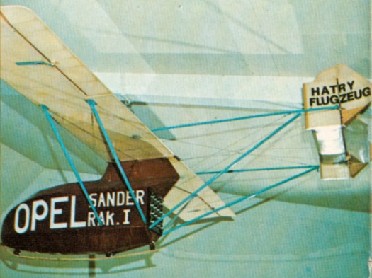
A number of designs were built with money provided to the VfR (Society for Space Travel) in Germany in the late 1920s, by the publicity ¬seeking automobile tycoon Fritz von Opel. First to fly was the tail-first Ente (duck) designed by Professor A M Lippisch, pilotd by Fitz Starrier, it made a rocket propelled flight of about 4,000 ft (1220 m) lasting some 70 seconds, on 11 June 1928. However, it was virtually uncontrollabe and made only two further tests.
Fritz von Opel had performed a number of publicity stunts involving rocket-powered cars for his Opel motor car company. Along with Friedrich Sander, a pyrotechnics manufacturer and Max Valier, a rocketry advocate, Opel concocted a scheme to attach two rockets to an Alexander Lippisch designed tail-less glider. In the summer of 1928, the three men brought the glider, called “Ente” to Wasserkuppe and hired Fritz Stammer to test it.
Two black powder rockets were attached to the skids on the underside of the fuselage. They were to be electronically fired from a switch in the cockpit. In order to adjust the center of gravity as the powder burned, a counterweight system was positioned under the floor. The rockets were timed to be fired one after the other to provide continuous thrust. Each rocket was intended to burn for about thirty seconds.
The Rak.1, designed by Hatry and flown by von Opel, took off from a raised track on 30 September 1929. After one false start, the rocket fired and the aircraft roared across the grassy field and into the air. Stammer reached an altitude of 1,500 meters (4,900 ft.), circled the mountain and landed safely. On the second flight, the team decided to fire both rockets simultaneously thereby doubling the thrust for a 30 seconds burn. At the instant of launch, one rocket fired, but the other one appeared to sputter and as the plane left the ground, it exploded. The blast tore holes in both wings and set them on fire. Amazingly, Stammer brought the burning aircraft back to ground from an altitude of about 65 feet and quickly abandoned it. The aircraft was a total loss, as was Fritz von Opel’s dream of rocket-powered gliders.
Powered by: Sixteen Sander solid fuel (powder) rockets, each of 55 lb (25 kg) thrust, mounted in four banks of four and fired in stages. Attained speed: 95 mph (153 kph). Distance flown: approx 5,000 ft (1,525m). Accommodation: Crew of 1.
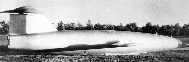
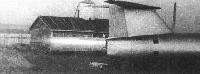
The “346-3” with the ski gear unfolded and the stabilization straps under the wings
In October 1946, a group of aeronautical specialists from Junkers and Siebel firms was transferred to the USSR and located on the territory of Factory No. 458.
The OKB-2 was created in order to design and study experimental aircraft with liquid reactive rockets (ZhRD).
The OKB-2’s first task was the study, construction and development of the tests of the aircraft “346” with a two-chamber liquid reactive engine.
The “346” was a development of the German DFS-346. A single copy of this model, almost in the final phase of construction, was destroyed by the fascists in 1945 so that it would not fall into the hands of the Soviets, but a large number of components and mechanisms were preserved that facilitated the construction work. The working group under the leadership of Hans Rössing, on September 29, 1946 completed the construction of a DFS-346 in the workshops of the Siebel aeronautical factory in Halle. After some tests on the ground the plane was shown and sent to the USSR. In a joint work of OKB-2 – TsAGI, a program was developed to use the Soviet development “346” as a flying test bed, with the aim of achieving speeds close to those of sound and studying the behavior of the aircraft in this environment, defining the loads and their distribution throughout the fuselage and the wings of the aircraft.
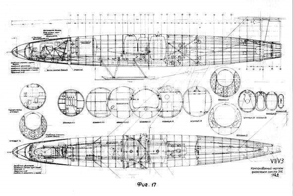
The “346” was designed as a monoplane with aerodynamically clean lines, with a mid-wing and a 45° sweep at the leading edge.
The main notable features of the “346” were: Removable hermetic cockpit conceived in such a way that it did not protrude in the line of the fuselage; Integral stabilizer with variation of the angle of incidence by + 2 °; Retractable ski undercarriage.
The entire aircraft was built in metal with a light sheet coating, except for the removable airtight cabin, which featured a wooden structure. The fuselage was made up of three sections. The front section, with a circular section, was obtained by rotating the NACA 00121-0.66-50 profile, with the entire glazed nose movable to allow access for the pilot. The central portion had a cylindrical shape that became a vertical oval towards the tail.
Detail of the opening of the nose to allow access to the pilot.
The wings had a NACA-012 profile of 12% thickness. The flaps and landing gear retraction were operated by a pneumatic system using gas balloons. The ailerons featured double section. At low speeds the inclination of both sections was the same, but at high speeds only the outer sections moved.
The tail was T-shaped with integral movable stabilizers with angles from -2º40 ‘to + 2º. The elevator had two sections, which, like the ailerons, were inclined at different angles depending on the flight regime.
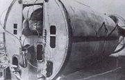
The cockpit was attached to the fuselage by means of a hermetic gasket and featured a transparent plexiglass cover that moved to allow access for the pilot. This one was located lying down, with the look forward and in case of emergencies he could activate a system to detach the sealed cabin from the fuselage (with the help of explosive screws) and descend by parachute. This emergency system worked even in case the pilot had lost consciousness. Faced with certain uncontrolled reactions of the plane, a rescue system was activated that made the cabin detach from the rest of the aircraft and amortized its fall. For this purpose, the cabin featured a stabilization parachute fixed to its rear wall. Upon reaching 3,000 meters, the pilot was catapulted out of the cockpit by means of an automatic system that detached the cover. About 1,500 meters above the ground, the pilot’s parachute opened.
The decision to use a ski gear instead of a wheeled one was based on the fact that the “346” was designed to be launched from mother aircraft, so it did not need a landing gear to guarantee take-off. In all versions (except for the “346-P”) the undercarriage, once retracted, was covered by two panels to reduce aerodynamic resistance. A small steel skid was located under the tail. In the “346-3” version, curved metal skis were used under the wings to maintain the balance of the aircraft after landing.
In the ” 346” there were two Walter 509-109 reactive engines mounted on a common structure. This powerplant consisted of two superimposed chambers, one of which turned on whenever the engine was started. The other camera could be activated for short periods of time when maximum motive power was required. The cruise chamber developed 300 kg of thrust at sea level and the main chamber 1700 kg. The combined power at high altitude was approximately 2250 kg. Due to the high consumption this fuel guaranteed the work of the engine only for a few minutes. Just behind the cockpit was located the 1,100 kg tank with concentrated hydrogen peroxide (called T-Stoff in Germany) and in the central fuselage the methanol / hydrazine hydrate tanks (called C-Stoff) with capacity were interconnected for 552 liters of fuel. A system of pumps working with calcium permanganate injected the components into the combustion chambers.
In the USSR preparation of the flight of the “346” was carried out. Taking into account that the pilot had to steer the aircraft in a lying position, several experiments were carried out in the LII related to the particularities of this position. For this purpose, a DFS Kranich glider was specially prepared so that it could be piloted lying down. This glider was tested by a group of German and Soviet pilots, including Mark L. Galai, who described the position as “extremely uncomfortable.” Despite these assessments, it was impossible to change the cabin configuration, as it practically meant making it new and, on the other hand, it would significantly spoil the performance of the aircraft.
In the LII the detachment tests of the cabin and the catapult system were also carried out for emergency situations. For these tests, a “346” cockpit was prepared with a life-size mannequin. This cockpit was attached to the belly of a B-25J and tested successfully.
The emergency capsule tested from a B-25
The TsAGI played a major role during these preparations. Aerodynamic tests carried out in the T-101 tunnel of the TsAGI from March 1947, showed that at large angles of attack there was great turbulence at the wingtips. With the increase in speed, this turbulence spread through the wing, causing the loss of stability. It was concluded that this turbulence expanded because the wing had the same profile over its entire span. In order to combat this problem in the second example, four aerodynamic blades were added in the upper wing designed to break the flow along the entire length of the wingspan. This solution was later applied to virtually all Soviet swept wing aircraft developments of the 1950s – 1960s
Tests of the “346” in the T-101 tunnel of the TsAGI.
A model of the “346” was prepared and tested in the first high-speed wind tunnel in the USSR: the T-106 of the TsAGI. Testing at this facility demonstrated the loss of effectiveness of control surfaces as speed approached that of sound. This led to the decision not to exceed Mach 0.8 speed in manned flights.
Finally, after completing the aerodynamic tests, the example brought from Germany in 1946 was destined to carry out static resistance tests, until it was destroyed.
In the second half of 1948 the OKB-2 finished the construction of the glider version of the plane, designated “346-P”. Unlike the original model, this glider was built as a simplified version, lacking the sealed cabin, engine, and fuel tanks. Another detail was the removal of the panels from the undercarriage aerodynamic fairing. With the help of ballast, it was possible to modify the aircraft’s center of gravity in an operative way. The weight of the aircraft reached 1180-2180 kg.
The main objective of the “346-P” was to develop the launch system from the mother plane, the stability tests in flight and the control of the aircraft with different positions of the center of gravity. Another no less important objective was to test the piloting from the lying position and landing on the ski. The test pilot for the “346-P” was Wolfgang Ziese, formerly chief test pilot for the German firm Siebel Flugzeugwerke and with 20 years of experience flying different aircraft. As lead engineer for the tests, V. Ya. Malochayev was selected.
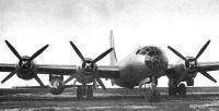
The first flight of the “346” in glider configuration was made on May 10, 1951. Between 1949 and 1949 the “346-P” made four flights using as mother ship one of the Boeing B-29 Superfortress (ex-USAAF 42 -6256) held in the USSR (and used as a material basis for studies to build the Soviet copy as Tupolev Tu-4). The “346” was fixed on a beam located under the right wing, between the two engines.
The B-29 mother plane prepares for flight.
The B-29 rose to the height set for the test, releasing the glider that began the descent towards the ground. Three of the flights went smoothly and in the fourth, Ziese, at the time of detachment, could not control the ailerons, so the plane turned over. With great work it was finally possible to stabilize the aircraft and land without further complications.
On 5 May 1949 the factory handed the “346-1” for testing. This model fully corresponded to the project except for the installation of a model instead of the reactive engine. The weight without fuel reached 3125 Kg.
The “346-1” under the wing of the B-29 mother plane.
Throughout the summer the preparatory work for the flight of the “346-1” was carried out at the Tiopli Stan airfield. The first flight of this model took place on September 30, 1949. The 3145 kg aircraft was lifted under the wing of the B-29 piloted by AA Efimov and NA Zamyatin to 9,700 meters. Following the detachment of the mother plane, Wolfgang Ziese began the descent. Upon reaching a height between 2,500 and 3,000 meters, it deployed the landing gear and began the approach. The calculation during the landing was not correct and the aircraft approached the runway with a high landing speed close to 310 km / h. The plane touched down and bounced to a height of 3-4 meters, covering a distance of close to 800 meters. During the second landing, the ski was picked up and the plane began to roll down the runway, moving on its belly. The pilot’s seatbelt system proved unsafe, so Ziese was thrown forward, his head hitting the cockpit deck structure and he lost consciousness. Luckily the traumas were not serious and after some time in the hospital Wolfgang Ziese was able to rejoin the tests.
The investigation commission, led by test pilot NS Rybko, concluded that the accident was caused by an error by the pilot, who, concentrating on controlling the aircraft, failed to fully deploy the landing gear. This flight showed that the behavior of the plane was still not very predictable, so it was decided to postpone the powered flight until the pilots had control of the flight, which required more test flights in a glider configuration.
The ” 346-2 ” or ” D ” was the ” 346-1 ” itself after repairs, but with the mock-up replaced by the actual powerplant. During Ziese’s time at the hospital the tests were continued by LII test pilot PI Kazmin. On its first flight, in October 1950, the ski could not be fixed after being extended, so it was also picked up when the airplane landed, but in this case the runway was covered with snow, so there was no considerable damage to the aircraft.
The “346-2” damaged after Kazmin’s landing on the belly in October 1950.
A short time later Kazmin made a second flight, this time towed by a Tupolev Tu-2, which released him at an altitude of 2000 meters. After being released, he made a free flight downhill, which also culminated in a bad landing due to the pilot landing before the start of the runway. Again, the plane had to be sent for repair.
Despite the landing accidents, it was concluded that the aircraft was controllable in flight and for this reason it was decided to move on to the main segment of the test program: flight with the reactive engine activated. For this purpose, a third example with an engine known as “346-3” was prepared.
The assembly of the “346-3″ culminated in May 1950. It differed from the “346-1” in the shape of the tail planes with greater sagging and thinner profile. As a result of these changes the calculated speed of the ” 346-3 ” grew to Mach 0.9.
Reactive engine tests on the ground before the first powered flight.
The reactive engine was tested on the ground on this model. The results obtained allow obtaining approval to carry out the powered flight tests. During the preparation for these flights, a high deterioration of the tanks, pipes and structure was observed, due to the action of the acid used as an oxidant. The OKB-2 carried out important works aimed at studying the causes of the corrosion of the ZhRD and the search for technological solutions.
For the tests of the “346-3” about 100 km southwest of Moscow, near the city Lujovits, the construction of a new factory airfield began. The preparation of this new aerodrome and the transfer of the necessary technology there took several months.
The tests of the “346” were carried out in extremely difficult conditions due to the fact that the new industrial aerodrome in Tretyakov (Lujovits) lacked the most basic services: there were no hangars or workshops, there was no electricity or water supply. The runway lacked surface and was extremely short (despite being somewhat longer than the one previously used).
At the beginning of 1951 and after returning from the hospital, Ziese began to conduct flight training in the glider “346-P” and on April 6 made a first flight in the “346-3” without starting the engine from the B-29.
The 346 during the approach to the runway.
On 15 August 1951 the first flight was performed with the engine running. Due to the limitations imposed by the TsAGI in relation to the maximum speed, only one of the combustion chambers was activated, so the maximum thrust reached only 1570 kg. The reactive engine was activated at the altitude of 7000 meters, one minute and 40 seconds after the detachment, and worked for 1 minute and a half, then the glide flight and landing was performed.
The flight was extremely difficult. When the engine started, there was marked lateral instability. Ziese was forced to keep a tight grip on the ailerons. The situation became more unbearable due to the poor performance of the cabin temperature regulation system, which caused it to rise above 40ºC.
After the flight, work was done on the cabin ventilation system. The second powered flight was carried out without major complications on September 2, 1951.
On 14 September 1951, the third planned flight ended in an accident. Ziese detached from the mother plane at an altitude of 9300 meters. After starting the engine, the plane continued its climb with increased speed. After two minutes of engine work, the speed exceeded 900 km / h, a moment later Ziese reported by radio that the plane lost control and began to fall. By order of the ground control, he was directed to leave the plane. The emergency system worked perfectly. The cockpit was detached from the rest of the aircraft at an altitude of 6500 meters and the stabilization parachute opened without problems. The automatic system allowed Ziese to evacuate upon reaching 3,000 m and landed, damaging one leg. The plane fell to the ground and caught fire near the Smolenskie Borki village.Shortly afterwards Ziese became seriously ill and died, being buried in Ivankovo village. Later his mother requested the transfer of his remains to Germany.
The “346” preparing for flight.
The specialists who participated in the investigation of the accident did not reach a single conclusion. One group of specialists concluded that the aircraft went into a spin due to human error by the pilot, while another group considered that Ziese reached the maximum allowable speed for the design, thus considerably increasing the pressure on the wing and tail, caused the loss of control of the aircraft.
Since the speed of 900 km / h had been reached, using less than half of the motive power, it could be assumed without margin of error that the speed of sound could be exceeded, but the structural and aerodynamic limitations did not allow these values to be achieved.
Despite the accident, it was considered that the investigative tasks posed to ” 346 ” were fulfilled. When reaching speeds close to Mach 0.9 it was shown: The working effectiveness of reactive engines both on the ground and in flight. The excellent response of the emergency system. The possibility of piloting the aircraft from the prone position, allowing it to better withstand large overloads on the pilot’s body, in relation to the normal position. The possibility of landing the plane at speeds of up to 330 km / h using a ski gear and on the runway of unprepared airfields. The excellent rate of climb with the use of the ZhRD at all flight heights.
In the course of the tests, the values of 12000 – 13000 meters were reached as a ceiling and a maximum speed of 950 km / h. The maximum flow velocity reached was 100 m / s. The dive speed during the accident was calculated to be higher than the speed of sound.
After the accident the testing program continued, but was soon closed. Despite the positive results and still having one (“346-1”) with flight capacity, it was decided not to continue the tests because it was considered that they would not yield any additional relevant results. All possible results (given the technological limitations of the TsAGI at the time) had been obtained.
The development of the “346” was the most expensive experimental program ever developed at Factory No.1. In the period from April 1946 to September 1951, 55 million rubles were spent on this project.
Various parts and components of the ” 346 ” were donated to the Moscow Aviation Institute. The OKB-2 in April 1951 was transferred to Factory No. 492 in Savielov. At the end of 1953 the OKB-2 was closed. All German specialists were repatriated to the GDR.
Versions
DFS-346 – First prototype built in the facilities of the Siebel firm in Halle by a group of specialists led by Hans Rössing and transferred to the USSR in 1946. It was used for a set of tests by the LII and the TsAGI and finally destroyed during the development of the static resistance tests.
346-P – Unpowered model built on the OKB-2 and used for motherboard launch and flight behavior tests. Externally it was identical to the DFS-346 except for the aerodynamic undercarriage fairing, removed in order to reduce weight. It lacked a pressurized cabin, fuel tanks, and powerplant.
346-1 (A) – Version with minor modifications to the rudder and tail design and a mock-up of the reactive engine. It was damaged on its first flight.
346-2 (D) – 346-1 after repair with reactive motor installed. It was never engine tested.
346-3 – The only specimen tested in flights with a reactive engine. It was destroyed during the third flight after exceeding 950 km / h.