Wiseman 1910 Biplane

Fred J. Wiseman and Jean Peters working on their aircraft at the Laughlin ranch, 1910

Fred J. Wiseman attendance at the Los Angeles air meet that January cemented his ambitions to take up flying and to build an aircraft with his long-time racing partner and mechanic, Jean Peters (AKA J. W. Peters, Julian Pierre and John Peters). Funding the venture was a $10,000 investment by Ben Noonan, an old Santa Rosa friend and former business partner of Wiseman’s.

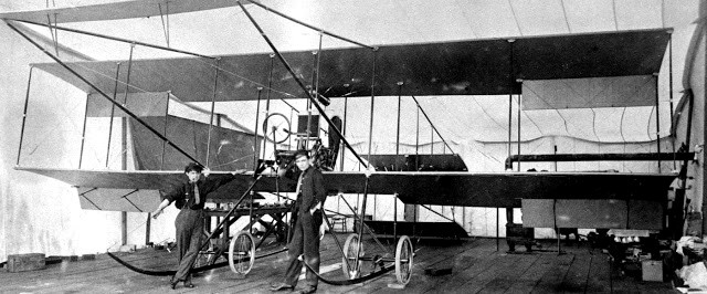
Working under a tent in a pasture – appropriately, about a mile northeast of today’s Sonoma County Airport – they began assembling the flying machine the pair had started designing in San Francisco. About six weeks later their first test flight occurred.

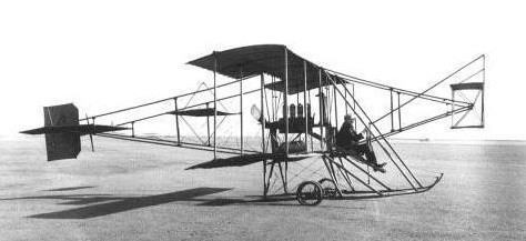
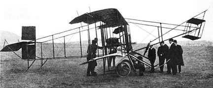
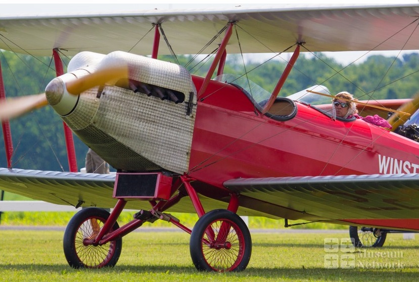
The Press Democrat printed a lengthy description of that version of their aircraft that will probably be of interest to historians (although not without mistakes; what they called “macadamite” was probably phenolic, for example, and poor Jean Peters was cleaved in twain, ID’ed simultaneously as “Julian Pierre and M. W. Peters”). The Press Democrat erred in writing they were building a “Farman biplane.” Today it’s recognized that they ended up mixing features from Farman, Curtiss, and the Wright brother’s designs. Given that the Wrights were already suing Curtiss for patent infringement, the hybrid Peters-Wiseman plane had the potential to win any competition for Aeroplane Most Likely To End Up In Court.

Events followed breathlessly by both of the town’s newspapers. Over forty articles about his doings appeared in one year alone. Reporter Tom Gregory flew one morning with Fred Wiseman and thus entered the record books himself as the world’s first terrified passenger.

“I had assured Wiseman that there was no limit to my nerve,” Gregory wrote in his Press Democrat essay, “but when I saw him monkeying around the engine of his bi-plane, and I looked aloft and saw the emptiness of things up there, I begin to get skreeky.”

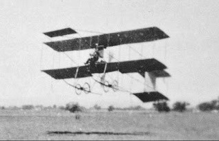
“How shall I describe it? Just as soon as the wheels left the ground we seemed to stand still, and every object around us and below us seemed to hurry past. There wasn’t a bump or jar, though occasionally a swinging sensation when Wiseman tipped his plane the fraction of an inch–infinitesimal things count for much up in the air–and we were pulling higher against gravitation…I didn’t do any talking or anything else except gasp and catch breath, but I noted that Wiseman was exceedingly busy. He would elevate and depress his altitude planes as we would strike a warmer body of air which would drop us–or a colder, which, being heavier, would buoy us up to a greater elevation. Of course we would fall first on one side and then the other, and Fred’s shoulders woud work the tilting planes in his almost-agony to get her level again. Once when we went over until I almost quit breathing he attempted a jest by saying our starboard wing had passed over somebody’s hot chimney…He picked a “soft place to fall on,” and killed the engine, and in the silence which seemed doubly silent after the boom of the motor and propeller, we glided softly down; the wide planes parachuting us in safety, to the old earth.”

Wiseman Biplane / Wiseman-Cooke biplane

The Wiseman Biplane, built by Frederick J. Wiseman and also known as the Wiseman-Cooke biplane, from 1910/1911, was a pusher that combined the designs of Wright, Farman and Curtiss. Claimed to be the first biplane to be flown in California, it was fitted with an overbored 4-cylinder engine from a “San Francisco engine company” by Frederick J. Wiseman, who increased the power output to 50 hp.

First flying on 23 April 1910, which makes puts this among the earliest California-built aircraft to fly, auto racer Wiseman and his mechanic, Peters, used their race winnings to construct this pusher (aka Wiseman-Peters)—admitted by Wiseman to have incorporated design features of Curtiss, Farman and Wright from notes, photos, and sketches of these planes seen at air meets, with innovations like laminated wing ribs, front and rear elevators, and trailing-edge ailerons on all wings.

First flown in Sonoma County, piloted by Wiseman, then, with a 60hp Hall-Scott A-2, at Petaluma on 24 July 1910 piloted by Peters.

Today it is displayed in the Smithsonian’s National Postal Museum in Washington, D.C. after being restored in 1983-1985 by NASM.

Engine: 50hp Wiseman-modified local-make auto engine
Wingspan: 24’0″
Length: 25’0″
Seats: 1

Winton Sportsman

The Sportsman is the latest release from Col Winton on the Gold Coast who has been designing and building ultralights over the last nine years. The mid wing pusher comes either in kit form with or without the engine or complete and ready to fly. The sleek fibreglass body can be removed for maintenance or for those who like that airy feel, and the cantilevered mid wing unbolts for trailering a channel section aluminium boom supports the tail “feathers”. This aircraft can use a Rotax engine in lieu of the VW unit.

Gallery

Engine: VW 1400cc
Prop: 137cm x 71 cm pitch
Wing span: 7.6 m, 10.7 sq m
Length: 4.6m
Weight: 150 kg
Cruise speed: 70 kts
Stall: 30 kt

Winton Jackaroo

Since designing the Grasshopper, Col has produced the Jackeroo. The aircraft uses composite construction wings and a fuselage based on a 6 x 4 inch (152 x 102 mm) tube of rectangular section. The Mk2 version of the Jackeroo uses a deep section wing, with depth 20% of chord, which Col chose to lower the landing and take off speeds. However, to his surprise, it also improved the Jackeroo’s cruising speed.
Assembly time for the Mk2 Jackeroo from a trailer is 10min, and the aircraft weighs some 250lb (113kg) empty.

Winton Grasshopper

Single seat single engined mid wing mono¬plane with conventional three axis control. Wing has swept back leading and trailing edges, and tapering chord; cruciform tail. Pitch control by fully flying tail; yaw control by fin mounted rudder; control inputs through stick for pitch/roll and pedals for yaw. Wing braced from above by cables; wing profile Karman; 100% double¬ surface. Undercarriage has three wheels in tricycle formation. Push right go right nosewheel steering connected to yaw control. Aluminium tube/glass¬fibre fuselage, partially enclosed. Engine mounted above wing driving pusher propeller.

Col Winton’s Grasshopper won an award for the best foreign ultralight at the 1981 Oshkosh being a sophisti¬cated design, even by 1983 standards. Using Karman aerodynamics for both fuselage and wings, this machine was original¬ly powered by a 432 cc two stroke developing 23 hp. However, following its win at Oshkosh, Pterodactyl Ltd agreed to market the aircraft in the US, using a 30hp Cuyuna, while Col himself had plans to re engine the machine with a 440 cc Robin.

In concept the Grasshopper is a mixture of composite and tube and Dacron construc¬tion. The fuselage is principally made from glass fibre, while the wings are tube and Dacron with glass fibre leading edges and tips. Wings can be removed for transport and storage. The undercarriage has suspension on all three wheels and sometimes wheel spats are fitted.

Tolhurst purchased the moulds and rights from Colin Winton and produced an updated model at Camden, Sydney, Australia.

In 1978 the aircraft was purchased by Mr Juan Humberto Burnett of Perth and used for recreational flying mainly in the Rockingham area from 1978 to 1979. During this time, Burnett made a forced landing on a dry saltlake at Rockingham, due to a blocked fuel line.

Burnett moved to Mt Newman in 1979, and made several long distance flights from that town. One such flight was to Lake Disappointment and return (during which extra fuel was carried), and another flight was made to Port Hedland. The machine crashed on two occasions whilst based at Mt Newman. Once at Newman itself, and once at Marble Bar. In both incidents, damage to the machine was minimal and Burnett was unhurt.

In May 1981 Burnett returned to Perth, and did not get the opportunity to fly the Grasshopper again. The slightly damaged machine was donated to the RAAF Assn. Aviation Museum, where a rebuild was undertaken to bring the machine up to display condition.

On 25 April 2008 it was purchased from the Aviation Heritage Museum, Bull Creek by Greg Ackman who loaned the aircraft to the Queensland Aviation Museum. On 17 July 2008 it arrived at QAM, Caloundra by road. The aircraft was later donated to QAM.

Have acquired and earlier model grasshopper and am seeking to identify what model and year it was constructed, i also wish to get my hands on a construction manual as i want to restore this aircraft back to its original flying state,
Will White
ima224ru12@yahoo.com.au

Engine: Robin EC44PM
Prop: VAC 36 x 50
Wingspan: 27 ft 11.5 in / 8.52 m
Length: 16 ft 4.75 in / 5.0 m
Empty wt: 122 kg
AUW: 249 kg
Cruise: 60 kts
Max level speed: 75 mph, 120 kph
Initial Climb: 192m/min / 630ft/min
Service Ceiling: 3 962m / 13 000ft
Range: 483km / 300mile

Winstead Special

A one off, the Winstead Special was built by Carl Winstead in 1926, and flown in the Flying Aces Air Circus in the late 1920s. It was a hybrid with a Travel Air fuselage and Swallow wings used for sport racing competition as N2297, piloted by J J Davis. The fuselage is believed to be the steel tube fuselage Walter Beech and Lloyd Stearman built while working for Swallow, but their idea of steel tubing was shot down by Jake Moellendick, president of Swallow at that time. The fuselage was set aside, then sold.

Carl flew it with the Flying Aces Air Circus, Jessie Woods walked its wings. Carl also raced it and barnstormed with it. The next owners, the Marvin Mara family, used it for racing and barnstorming. It changed hands several times until the Davis Family of Ary NB purchased it in 1935 and took it apart for a rework in 1937. It was never reassembled until the remains were found c.1975 in storage and purchased by Paul Dougherty Jr in 1994.

The aircraft was still flying at the Golden Age Air Museum in Bethel, PA, in 2018.

Courtesy David Eckert, Golden Age Air Museum

Engine: Curtiss OX-5, 90h
Wingspan 29’6″
Length: 23’0″
Empty weight: 1281 lb
Gross weight: 1800 lb
Seats: 3

Wings of Freedom Flitplane

A very low cost, tube and fabric ultralight which was available as plans, kit, or ready to fly. The plans did cost US$100, and ready to fly US$10,500.

Doug Widmar / Dwidmar@comcast.net
Jan 2014
I have one and wonder how many are out there and flying. So Far I’ve just got all three wheels off the ground high speed taxi. Ran out of summer 2013. Looking forward to 2014 actually flying it.

Top speed: 63 mph
Cruise: 45 mph
Stall: 27 mph
Range: 120 sm
Rate of climb: 400 fpm
Takeoff dist: 300 ft
Landing dist: 300 ft
Service ceiling: 8000 ft
Engine: 2si (LAPS), 32 hp
HP range: 25-40
Fuel capacity: 5 USG
Empty weight: 245 lb
Gross weight: 500 lb
Height: 5 ft
Length: 15.8 ft
Wing span: 27 ft
Wing area: 145 sq.ft
Seats: 1
Landing gear: tailwheel

Wing D-1 Derringer

By 1962, George Wing had moved on to the development of John Thorp’s little twin, which eventually became the Wing Derringer. George Wing hired John Thorp to design a high performance two seat twin. Thorp, who had been toying with the idea of hanging two engines on his Sky Skooter (one of which Wing owned), was already primed for the idea. They started with a clean sheet of paper and, using two Continental O 200 engines and fixed pitch props, came up with an airplane that was, for its operating costs, a wonderful performer, first built in 1978. John E Robey designed the major assembly tooling for the Wing Derringer at Olin-Dixon in Coffeyville Ks in the late 1960’s. Derringer project leader was Larry Heuberger.

The prototype carried two special Continental 115 hp IO-200 engines with fuel injection. The cowling was 21.5 inches deep. The prototype N3261G first flew on 1 May 1962, kept throwing prop blades, however, its engine out performance was inadequate, and the tweaked engines were not a realistic choice for a production airplane; and so eventually, production prototypes were equipped with 160 hp Lycoming engines. Originally, the Derringer was equipped with very thin, narrow bladed racing props.

While testing the prototype, the next two units were nearing completion in Torrance, California.

The airplane was a compact two-seater with a huge baggage bay behind the seats, a simple rectangular wing and a fuselage that was all curves from nose to tail. Its structure used stretched chem milled skins throughout. With stretch-formed, chemically-etched skins, the number of metal pieces requied is greatly reduced and labour time is cut accordingly. The Derringer has eight fuselage pieces and there isn’t a flat surface on any of them. There are only 13 major skins in the entire plane with the wing a single wrap-around sheet .064 thich where ribs and attachments occur. Remaining metal is etched away to .032 where no stresses occur. The wing walk for instance is .064. Metal skins start out at .064 or .040, depending on their function, and are etched down to whatever thickness the specs call for.

The flight test and production models, under construction in 1964, were to be equipped with 150 hp Lycoming IO-320 engines that operate on 80/87 octane fuel. The production aircraft would have full-feathering, constant speed, two-blade Hartzell props.

Matched-hole tooling means the Derringer can be assembled with a minimum of jigs and fixtures. All holes were to be in a temperature-controlled room so that the parts for number 2 and 3 aircraft were interchangeable with any others, All skin assembly is butt-jointed and flush riveted.

Derringer no.2

The prototype had a fuselage two inches narrower than the production model and was fitted with a slide-back cover. The prototype had a hand brake while the production craft were to have toe brakes. A simple automotive window motor operates the Saginaw ball and screw system for gear retraction and flap movement.

The Derringer undercarriage is fitted with three oleo struts, each with 9 inches of travel.

It would cruise at 190 knots, climbing at 1,700 fpm and boasting a range of over 1,000 nm with reserves.

There is no steering on the ground except with the engines.

Pre-take off check list
Fuel on
Crossfeed off
Trim set
Mixture rich
Flaps 10 deg
Controls free
Canopy locked

Landing check list
Mixture rich
Gear down and locked
Flaps as desired

First deliveries were expected in the Spring of 1964, priced at $27,500.

Wing spent $3 million of his own money, $5 million all told, in developing and certificating the airplane.

Wing contracted with a Kansas manufacturing firm, Olin Dixon, to manufacture an initial production of five with 150hp, ATC A9WE, in 1966, and a second production with 160hp. Problems developed, which Olin blamed on Wing and Wing blamed on Olin. Litigation followed. The first 3 if the initial production were built by Wing’s Transland company

In 1979 Wing Aircraft’s two seat Derringer twin seemed to be on the verge of entering the general aviation marketplace at $40,500. Company President George Wing said that the first production Derringer were to be delivered in the fall. The aircraft, which is powered by two 160 horsepower Lycomings, has a book cruise speed of 182 knots at 65 percent power. Sea level rate of climb is 1,700 feet per minute, and the empty weight is 2,100 pounds. An IFR equipped Derringer was to sell for about $100,000.

Gallery

Prototype
Engine: Continental IO-200, 115 hp
Props: fixed pitch
Wingspan: 29 ft 2 in
Cabin height: 5 ft 7 in
Fin top: 8 ft
Fuel capacity: 2 x 44 USG
Wing loading: 22.15 lb/sq.ft
Liftoff speed: 90 mph
TO roll: 700 ft
Cruise climb: 130 mph / 1200 fpm
UC down max: 125 mph
Stall speed: 66 mph
SE critial speed: 77 mph
Cruise speed 75%: 250mph at 20,000 ft
Baggage compartment: 22 cu.ft
Baggage door is 10×30 in on thebleft side of the fuselage.
Cabin height: 48 in
Cabin width: 44 in
Cabin length: 98 in
Seats: 2
Gear cycling: approx 6 sec

Engine: 2 x Lycoming O-320-B1C, 160 hp
TBO: 2000 hrs
Prop: Hartzell, 2 blade, variable pitch 66 in
Seats: 2
Length: 23 ft
Height: 5.8 ft
Wingspan: 29.1 ft
Wing area: 121 sq.ft
Wing aspect ratio: 7
Max ramp wt: 3050 lbs
Max take off wt: 3050 lb
Standard empty wt: 2100 lb
Max useful load: 950 lb
Max landing wt: 2900 lb
Wing loading: 25.2 lbs/sq.ft
Power loading: 9.5 lbs/hp
Max useable fuel: 522 lb
Climb rate: 1700 fpm @ 104 kt
Climb gradient: 981 ft/nm
Rate of climb @ 8000 ft: 1015 fpm
Service ceiling; 19,600 ft
SE climb rate: 420 fpm @ 96 kts
SE climb gradient: 263 ft/nm
SE ceiling: 8,000 ft
Max speed: 202 kt
Cruise @ 65% power @ 8,000ft: 182 kt
Fuel flow @ 65% power @ 8,000ft: 95 pph
Endurance @ 65% power @ 8,000ft: 5.2 hr
Stalling speed clean: 70 kt
Stall speed gear/flaps down: 63 kt
Turbulent air penetration speed: 148 kt