The prototype Grob G-116 was a four seat, composite 200 hp Lycoming powered single. A four-seat version of the Grob G.115, the G 116 first flew on 29 April 1988 (D-EGRF), and was certificated in 1989.
The unit price was to be DM173,000.
The prototype Grob G-116 was a four seat, composite 200 hp Lycoming powered single. A four-seat version of the Grob G.115, the G 116 first flew on 29 April 1988 (D-EGRF), and was certificated in 1989.
The unit price was to be DM173,000.
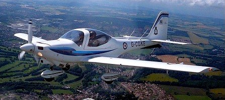
The Grob G 115 is an advanced general aviation fixed-wing aircraft, primarily used for flight training. The G 115 was first flown in November 1985.
Grob G-115 Heron / Tutor Article
By 1990 the G 115 had orders totalling more than 100 since production began in 1987. The two-seat, side-by-side light aircraft makes extensive use of composite materials in its construction and the resulting smooth finish gives low drag and high efficiency. The production G 115-C is powered by a single 150 hp (112 kW) Lycoming O-320-E2A piston engine driving a constant speed propeller.
The Royal Navy Flying Grading Flight operate the G.115D as the Heron.
Ninety-nine G.115E (at Tutors) were purchased for Air Cadets and University Air Squadrons in the UK. The E variant with a 3-blade variable pitch propeller is in Royal Air Force service as an elementary flying trainer.

G.115
Engine: Lycoming, 115hp.
Prop: fixed pitch.
Cruise: 121 kt.
Range: 621 miles.
ROC: 850 fpm.
G 115C
Engine: 150 hp (112 kW) Lycoming O-320-E2A
Propeller: constant speed
G.115D / Heron
G.115E
Engine: 1 x 134kW / 180 hp Textron Lycoming AEIO-360-B1F
Prop: Hoffman 3 blde CSU
Max take-off weight: 990 kg / 2183 lb
Empty weight: 690 kg / 1521 lb
Wingspan: 10,00 m / 33 ft 10 in
Length: 7,79 m / 23 ft 12 in
Height: 2,82 m / 7 ft 7 in
Wing area: 12,21 sq.m / 129.17 sq ft
Max. speed: 270 km/h / 168 mph
Cruise speed: 230 km/h / 143 mph
Initial climb rate : 1399.61 ft/min / 7.11 m/s
Service Ceiling: 4875 m / 16000 ft
Range: 1250 km / 777 miles
Crew: 2
G.115EG

The G110 got into an un-recoverable spin on its second spin flight. The pilot bailed out and the plane was destroyed. The pilot pulled the chute a bit early and some chute shrouds were cut by the prop. The pilot, a German TP, has no interest in flying any other Grob aircraft.
The program was cancelled two weeks later.

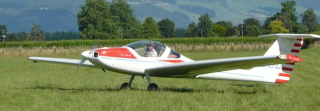
Designed by Burkhart Grob GmbH, the two seat Grob 109 motor glider features side by side seating and fixed tail dragger undercarriage with a steerable tail wheel. The fuselage and wings are made of industrial carbon fibre and glass fibre composites with air brakes. Glass Reinforced Plastic (GRP) is the main structural material with Carbon Fibre for the T-tailplane and rudder. Hard foam sandwiched between fibreglass cloth is used for stringers and formers in the fuselage as well as many other applications.
Grob’s G 109 has the ability to shed its wings, tailplane and elevators to enable it to be neatly packaged for transportation in a suitable road-borne trailer. Each wing has a tapered tongue that extends through the centre section to lock into the opposite wing root rib. The ailerons and air brakes are operated through push-pull control rods. The horizontal tailplane is fitted atop the fin and the quick connect fittings for the elevator and trim tab are fitted.
The Limbach L 2000 EB lA engine is rated at 59kw/80hp at 3,400 rpm. The engine has a single Slick magneto, twin Stromberg carbs with “pancake” sport air filters, Motorola alternator and a Hoffman feathering propeller with START (take-off and climb) and CRUISE pitch settings.
The 17.5 Imp gallon fuel tank is behind the cockpit and filled from above the left wing trailing edge. There are GRP skids/tie down points under each wing tip and the engine cooling air exits from fixed louvers in the bottom cowl.
The glassfibre monocoque fuselage has frames and longerons, while the low wing has a glassfibre roving main spar and a glassfibre/epoxy resin sandwich skin; there are aluminium air brakes in the upper wing surfaces. The fixed undercarriage has Scheibe hydraulic brakes on the spatted main wheels, and the tailwheel is steerable. The pilots sit under a one-piece forward-opening canopy and, after some flight testing, this was fitted with a central frame, while changes made to the undercarriage included moving the main wheels further back so as to unload the tailwheel, the main wheel struts being of steel. Wing span was increased from the original 15m (49ft 2.5in) to 54ft, the empty weight was increased and the motor cowling and wing roots were aerodynamically refined.
The prototype, D-KBGF, made its first flight on 14 March 1980, and the Grob G 109 was certified to JAR 22 in March 1980.
The prototype of the G.109B two-seat, side-by-side motorglider first flew in March 1983 as a version of the original G. 109, with increased span. The GROB G109B is a two-seat motor glider with T-type stabilizer, fixed landing gear and airbrakes. It is classified as a TMG (Touring Motor Glider). It was designed by Burkhart Grob GmbH and features side by side seating as well as a classical tail-dragger undercarriage with a steerable tail wheel. The fuselage and wings are made of industrial carbon-fibre and glass-fibre composites. The G109B’s engine was made by Grob (GR 2500) and is an aircooled 4-stroke flat engine.
In 1983 a Grob G109B motorglider extended the gliding world altitude record to 6,406m (21,018ft) and the gliding world altitude gain record to 5,042m (16,544ft).
Powered by a 75 hp (56 kW) Limbach engine, the G 109B in RAF service is known as the Vigilant T Mk 1 with the self-launching Volunteer Gliding Schools of the ATC and CCF. The Royal Air Force ordered the last 54.
Although production of this motorglider ceased in 1986, during 1990, Burkhart Grob Luft-und Raumfahrt was building between 70 and 100 more G.109Bs to meet a number of orders – including from the RAF.
A total of 322 of the G109 and 322 of the G109B aircraft were built from 1983 through to 1990.
In 1983 a Grob 109B extended the gliding world altitude record to 6406m / 21,018 ft and the gliding world altitude gain record to 5042 m / 16,544 ft.
G 109 / G 109B
Engine: 71 kW/ 95 bhp. Grob 2500
Wing span: 17.4m / 57.1ft
Wing area: 19sq.m / 204.5sq.ft
Empty Weight: 580kg / 1280lb
Payload: 245kg / 540lb
Gross Weight: 825kg / 1820lb
Wing Load: 40.44kg/sq.m / 8.28lb/sq.ft
Water Ballast: 0
L/DMax: 25 104 kph / 56 kt / 64 mph
MinSink: 1.10 m/s / 3.16 fps / 2.15 kt
Aspect ratio: 15.9
Airfoil: Eppler E580
Seats: 2
No. Built: 322
Engine: Limbach L 2000 EB 1A, 80hp @ 3,400 rpm.
Propeller: Hoffman HO-V62R/L 160T.
Span: 16.6m (54.45 ft).
Length: 7.9m (25.85 ft).
Height: 1.7m (5.51 ft).
Empty Wt: 606 kg (1336 lbs).
Useful load: 219 kg (484 lbs).
MTOW: 825 kg (1820 lbs).
Cruise @ 5,000 ft: 105 kts, 3,000 rpm, 16 litres/3/2 gals per hour.
Range (45 min res): 430 nm.
ROC: 530 fpm.
Best glide ratio: 1:30. Stall: 47 kts.
Min sink rate: 230 fpm at 51 kts.
Vne: 130 kts.
Load factor: Va (100 kts) +5.31-2.65,
Vne (130 kts) +4/-15.
Fuel cap: 80 lt.
Baggage cap: 20 kg (44lb).
Ldg dist: 223m (730 ft).
TO dist: 205m (673 feet).
Max X-wind: 11 kt.
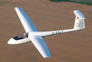
The G-102 Astir is a single seat glassfibre Standard Class sailplane, designed by Burkhart Grob. It was the first Grob-designed sailplane.
Construction of the prototype Astir CS began in March 1974. It features composite (fiberglass/resin) construction, a large wing area, a T-tail and water ballast. A Standard Class Sailplane, the large wing area gives good low speed handling characteristics. The main gear retracts. It first flew on 19 December 1974 and it went into production in July 1975 and soon proved to be popular, a total of 534 being delivered.
The cantilever mid wings have glassfibre roving main spars and a glassfibre/epoxy resin sandwich skin except for the ailerons, which are of glassfibre sandwich. There are Schempp-Hirth aluminium air brakes in the wing upper surfaces, but no flaps, and up to 220lb of water ballast can be carried in tanks in the wings, being jettisoned via a dump valve in the fuselage. Rigging is carried out without any separate removable parts as the wings and the tailplane are attached by a system of ‘snaplock’ connectors. The glassfibre semi-monocoque fuselage has a towing/launching hook, and the large one-piece cockpit canopy opens sideways to starboard.
Construction of the T-tail unit is the same as that of the wings.
This was followed by the Club II with similar fixed gear. A slightly improved version, the CS-77, was introduced in 1977. The CS-77 has a different rudder profile fuselage similar to that of the Speed Astir. The Astir CS 77 made its first flight on 26 March 1977; nearly 400 of the CS 77 and Club Astir had been built by the end of 1978.
The Club Astir II and the Standard Astir II featured the new fuselage of the Speed Astir II. with a one piece canopy, as well as the elasticated flaps of the Speed version and a new wing tip profile.
The Astir CS 77 has a retractable monowheel with an internally-expanding drum brake located ahead of the center of gravity, which folds up behind closed doors, and there is also a rubber-sprung tail wheel. The Astir CSM was a powered version under development in mid-1976 with a 25hp Fichtel & Sachs Wankel KM24 rotating piston engine on a retractable pylon aft of the pilot, driving a two-blade Hoffman tractor propeller. A 6.6 gal fuel tank is fitted.
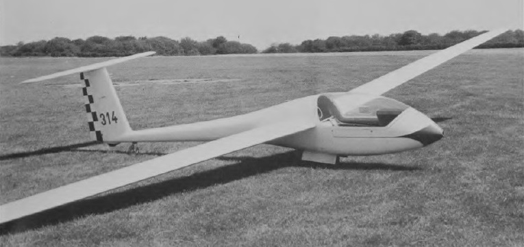
The Astir CS Jeans was of similar configuration to the CS 77, but with fixed wheel, and a tailskid.
The Standard III followed in the early 1980’s reverting to the higher profile fuselage and with reduced empty weight and increased payload. The Club III has a fixed main gear ahead of the center of gravity, and a tailwheel. The Club IIIB has a cockpit almost identical to the front seat of the two-place G 103 Twin II with a fixed main gear aft of the center of gravity and a nosewheel. Air Transport Certified (except Club II which is EXP). One, flown by R.R. Harris of the U.S., won the world absolute altitude record at 14.938 m/ 49.009 ft in 1986.
Production variants were the Club Astir III, IIIB and Standard Astir III, which have a roomier cockpit and reduced empty weight.
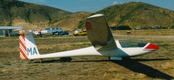
Grob 102
Wingspan: 15.00 m (49 ft 3 in)
Wing area: 12.4 sq.m (133 sq.ft)
Water ballast: 50 kg (110 lb)
Aspect ratio: 18.2
Empty weight: 255 kg (561 lb)
Gross weight: 450 kg (990 lb)
Maximum glide ratio: 38
Glide Ratio: 36 at 50 kt (92 km/h) / 5.9 nm (10.97 km) per 1000 ft
Sink rate: 141 ft/min (0.71 m/s) at 50 kt
Glide Ratio: 34 at 41 kt (76 km/h) / 5.6 nm (10.36 km) per 1000 ft
Sink rate: 122 ft/min (0.62 m/s) at 41 kt
At 90 knots (166 km/h)
Glide Ratio: 23 at 90 kt (166 km/h) / 3.8 nm (7.01 km) per 1000 ft
Sink rate: 393 ft/min (2.00 m/s) at 90 kt
Stall: (without airbrakes) 32 knots (60 km/h)
Stall: (with airbrakes) 35 knots (65 km/h)
Never Exceed: 135 knots (250 km/h)
In Rough Air: 135 knots (250 km/h)
Manoeuvering: 92 knots (170 km/h)
On Aerotow: 92 knots (170 km/h)
On Winch: 64 knots (120 km/h)
Airbrakes: 135 knots (250 km/h)
Gear Down: 135 knots (250 km/h)
Minimum Payload: 70 kg
Maximum Payload: 110 kg
Crew: One pilot
Astir CS Jeans
Wing span: 15m / 49.2ft
Wing area: 12.4sq.m / 133.5sq.ft
Empty Weight: 248kg / 547lb
Payload: 132kg / 291lb
Gross Weight: 380kg / 838lb
Wing Load: 30.64kg/sq.m / 6.27lb/sq.ft
Water Ballast: 0
Aspect ratio: 18.2
L/DMax: 33.3 93 kph / 50 kt / 58 mph
MinSink: 0.70 m/s / 2.3 fps / 1.36 kt
Airfoil: Eppler E 603
Seats: 1
No. Built: 337
G 102 Astir CS
Wing span: 15m / 49.2ft
Wing area: 12.4sq.m / 133.5sq.ft
Empty Weight: 255kg / 562lb
Payload: 195kg / 430lb
Gross Weight: 450kg / 992lb
Wing Load: 36.92kg/sq.m / 7.43lb/sq.ft
Water Ballast: 0
Aspect ratio: 18.2
Airfoil: Eppler E 603
L/DMax: 38 105 kph / 56 kt / 65 mph
MinSink: 0.70 m/s / 2.3 fps / 1.36 kt
Seats: 1
No. Built: 864
Grob G-102 Astir CS77
Span: 49 ft 2.5 in / 15.0 m
Length: 21 ft 11.25 in / 6.69 m
Height: 4 ft 7 in / 1.4 m
Wing area: 133.5 sq.ft / 12.4 sq.m
Aspect ratio: 18.2
Wing section: Eppler E603
Empty weight: 595 lb / 270 kg
Max weight: 992 lb / 450 kg
Water ballast: (220 lb / 100 kg
Max wing loading: 7.43 lb/sq ft /36.3 kg/sq.m
Max speed: 155 mph / 135 kt / 250 km/h
Stalling speed: 32.5 kt / 60 km/h
Max aero-tow speed: 105 mph
Max rough air speed: 135 kt / 250 km/h
Min sinking speed: 0.6 m/sec / 1.97 ft/sec at 47 mph / 40.5 kt / 75 km/h
Best glide ratio: 38:1 at 65 mph / 56.5 kt / 105 km/h
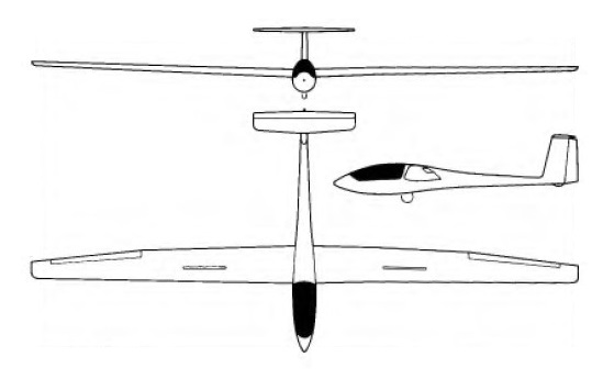
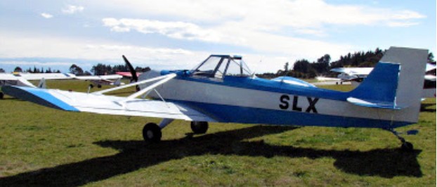
In New Zealand, Gavin Grimmer’s own design, the Grimmer Skylux (c/n 1005-2) is a single seat glider towplane powered by a converted Lexus V 8 engine. It was registered on 10/12/12, at Hastings, New Zealand, as an Amateur Built Aircraft. Gavin has had a lot of experience with automotive engine conversions in homebuilt aircraft with his Maranda ZK-JGR (which has the c/n 1005-1).
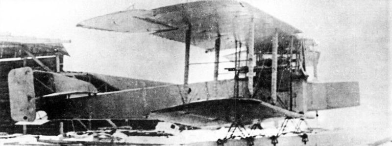
The bases of this project go back to an idea presented by Fleet Senior Lieutenant II Golenischev-Kutuzov, who proposed to build a special hovercraft capable of carrying out torpedo attacks on enemy ships. Little by little the idea of the hovercraft was derived from a specialized seaplane. This idea of Golenischev-Kutuzov was presented to PRTV for its implementation.
The plane began to be designed and built in 1916 at the Shchetinin Society. Co – engineered by Mikhail Mikhailovich Shishmariov, who headed the construction department at the Shchetinin factory. Shishmariov developed the entire technical project for the new aircraft, while Grigorovich was in charge only of the general conception of the model and the general direction during the preparation of the plans and technical documentation.
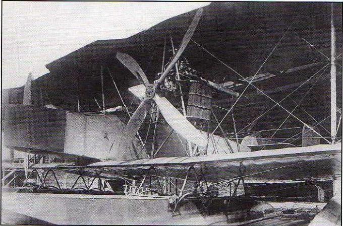
The GASN was designed as a huge twin-engine sesquiplane with a pair of floats and capable of carrying a 450-hp torpedo designed at the “Novi Lessner” factory in Petrograd. The power plant consisted of two 220 hp Renault engines located between both planes on steel tube supports and moving large four-blade propellers.
The initials GASN (Григорович/Шишмарев ГАСН) correspond to G idro Aeroplan S petsialnovo N aznachenia (Special Missions Hydroplane), although the model was also known as SON ( Samoliot O sobovo N aznachenia ) and in either of the two names it was considered to create an aircraft capable of carry and launch a naval torpedo, making this model the world’s first naval torpedo boat. We must add that this subject was considered highly secret, so in fleet documents references to the project are made as Type K.
The floats had a traditional construction similar to that used for the hull of submarines at the time and were fixed to the lower wing by means of uprights in an inverted V made of steel tubes with rubber attachment points.
The fuselage had a rectangular cross section secured by cables and covered with fabric.
The tail was of the biplane type with three rudders and a small keel on the central empennage.
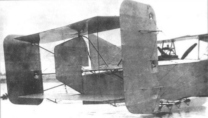
The large-span wing featured traditional wood-frame construction with fabric covering. The structure had three auxiliary spars to be able to fix the large ailerons. The shape in the plane of the wing was rectangular with a constant chord, but instead of being straight it presented a slight sagging.
The leading edge of the upper wing had indentations in the area of the propellers. The interplane supports were built with steel tubes on which they installed fabric-covered aerodynamic fairings and cable tensioners.
The GASN crew consisted of 3-4 people. In the bow area there was a position reinforced with sheets of plywood for an observer-gunner in charge of defending the forward hemisphere. Behind this position was the cockpit for two pilots and behind the wing box a third position for a gunner.
Even without completing the assembly of the first example, a request for the construction of 10 examples had been sent to Shchetinin.
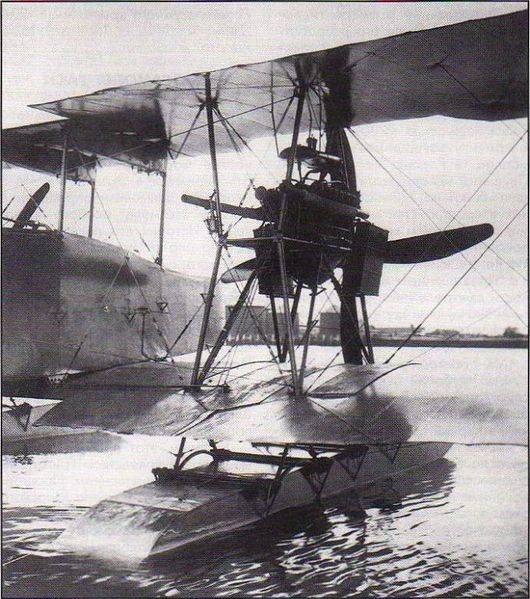
The first flight of the prototype took place on August 24, 1917 in Petrograd under the leadership of Senior Lieutenant A. Ye. Gruzinov. The first tests showed that the GASN had good behaviour in the water and was easily controllable, but it was necessary to modify the trim and improve the response of the rudders. It was proposed to advance the engines, locate certain weights and increase the wing’s rake angle to advance the center of gravity of the airplane. It was also proposed to increase the surface of the rudders.
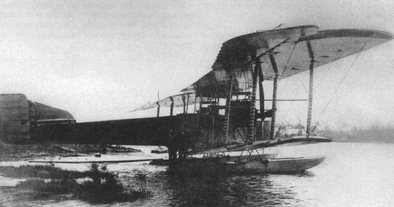
On September 24, during one of the flights, one of the floats was damaged, showing the need to reinforce its structure. After the repairs the plane began to fly again. These flights produced another series of problems, which is why the possibility of the Navy not continuing development and adapting the “Ilya Muromets” bomber or the Jioni twin-tailed plane for this role was considered.
The events of the revolution in Petrograd and the chaotic situation of the first years of the revolution prevented further development. Despite these factors, the GASN and an important set of construction elements of the started series of 10 copies were preserved intact, initially at the Shchetinin factory, which had changed its name to “Gamayún” and later at the “Krasni Liotchik” Factory.
The intention to continue the works would arrive in 1920. In that year Grigorovich traveled to Moscow and received an engineering post in Glavnoavia. His first task consisted of trying to continue the development of the projects stopped in the period 1917-1918. Grigorovich proposed to restore the work on the GASN torpedo bomber, knowing the state of conservation of the prototype and a good number of parts and components to assemble various aircraft of this type.
In November 1920 the GASN was made airworthy and the pilot LI Giks began carrying out the tests. Dmitri Pavolvich was on the shore supervising the process. On the 4th of that month, after long checks on the state of the engines, the mechanic Ozolin told Giks that the plane was ready for flight. The pilot stood in the cockpit and gave instructions to release the seaplane into the water.
During takeoff runs, tabs of fire began to come out of the exhaust pipes of one of the engines. Fearing a fire Giks decided to interrupt the test.
The engines were once more overhauled and the plane was finally cleared to take off, despite the fact that the weather conditions had deteriorated with a southerly wind that made take off difficult and the appearance of floating ice in the bay.
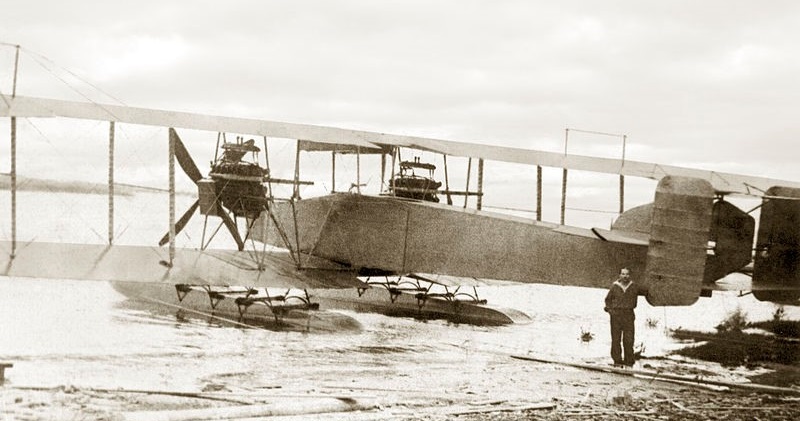
Steering the plane in the direction of Volni Island, Giks turned the plane upwind and took off. The plane was beginning to climb without difficulty when suddenly the engine on the right stopped working. The pilot turned for a landing near Krestovski Island. After gliding, the pilot managed to land and tried to steer the seaplane with a single engine. It was found that the seaplane’s rudder was ineffective and the aircraft only rotated around one axis. Giks directed the mechanic to go to the wing to try to compensate by sinking the float, but that didn’t help either. Waiting for help Giks switched off the engines. The plane began to drift freely.
The crew members removed the cushions from the seats, sprayed them with gasoline and lit them, throwing them near the plane as a signal for help, but help did not appear anyway.
For a whole day the plane drifted. At dawn the crew confirmed that they were about three kilometers from the shore and that the entire plane was surrounded by sheets of ice that made rescue difficult. Finally it was possible to bring the plane to the shore. The analysis of the accident showed that during the preparation of the flight, instead of oil, it was poured into the diluent tank.
With this the development came to an end.
GASN
Power plant: 2 x Renault, 220 hp
Upper plane wingspan: 28.0 m
Wing area: 150.0 m²
Length: 14.50m
Payload: 1450kg
Speed at sea level: 110-120 km/h
Accommodation: 3 – 4
Armament: two machine guns
Bombload: 450 kg torpedo or 480 kg of bombs

Between 1915 and 1916 at the Shchetinin Factory and based on a Grigorovich project, two “land” models were designed (in Russian Sujoputnie and hence the S in the name as opposed to the M for Morskoi or naval). The objetive of these models was to increase the performance of the Farman biplanes that the factory built under license.
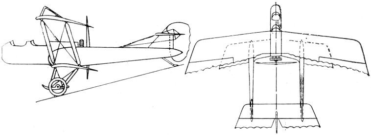
The first of these projects, known as S-1 (Григоровича С-1), was designed as a conventional biplane heavily influenced by Farman’s designs and equipped with a rotary engine. Construction was abandoned before the prototype was finished.
A second model, called S-2, was designed as a two-seater aerial observation and reconnaissance aircraft and generally repeated the successful scheme of the Farman biplanes with a central nacelle and a rotary engine. As a “novelty” it is worth noting the use of double tail cones that ended in individual empennages joined by the stabilizer with the elevators.
The selected powerplant was the 100 hp French Gnôme Monosoupape.
The entire construction was made of wood, covered with fabric. The wings had an Eifel-36 profile and were characterized by a large difference in span between both planes and the use of parallel uprights with cable tensioners.
The S-2 was built and its assembly was completed in January 1916. During flight tests, conducted by pilot Ya. I. Siedov, an accident occurred and the plane was not restored as it was considered that there was no point in trying to improve the outdated Farman designs

As early as 1915, a group of naval pilots had asked the Fleet for a long-range aircraft capable of carrying out long patrols, covering the entire Baltic Sea area. The start of the war increased the requests and increased when the conflicts with Turkey began.
On August 12, 1915, a meeting of the Aviation Committee of the Baltic Sea Liaison Service took place, in which once again the issue of the need for the provision of large seaplanes with a 6-hour patrol capacity was discussed. Based on these requirements, the builder DP Grigorovich proposed to build such a device.
The Marine Cruiser (Mosrkoi Kreiser or MK (Russian: Григорович МК-1 “Морской крейсер”)) was designed in 1916 to meet the requirements of the Naval General Staff (MGSh) and was conceived to serve with the Baltic and Black Sea fleets in long-range reconnaissance and bomber functions.
The MK-1 was the largest Russian seaplane ever designed and it only yielded to the Ilya Muromets bomber with floats.
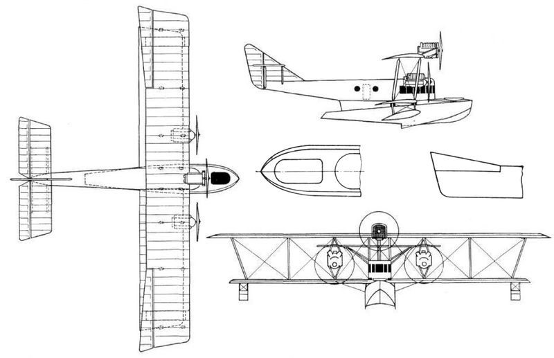
The MK-1 featured a center float, biplane configuration, three engines, and a four-crew capacity. From the technological and constructive point of view, the model maintained the characteristics of the designs developed in the Schetinin Factory.
A feature was that the float and fuselage were merged into a single structure, resulting in a general outline of combined features. This float had such dimensions that it could generally be considered a hull. In its lower region it presented a redentient with concave and lateral sides similar to those used in Grigorovich’s M flying boats. The construction of the internal structure of the float was made of ash with plywood covering.
In the forward region of the fuselage the closed cockpit was located, built with plywood and with good frontal glazing. At the rear, the fuselage appeared as a wooden frame braced by cables and covered with fabric.
The wing box was of the conventional type with three pairs of struts in each half plane and a certain offset. The upper plane was slightly larger than the lower plane and had trapezoidal-shaped ailerons. The wing structure was conventional, with two wooden spars and a rather slim profile. It should be noted that this wing box was fixed to the upper part of the float body by means of rubber shock absorbers with a travel of 180 mm.
In the tail section there was a wide triangular keel on which the horizontal planes were fixed, braced by uprights and the large-area rudder.
Originally it was thought to equip the MK-1 with only two 220 hp Renault engines located between the planes. Later, when construction began, the designers realized that the weight of the model exceeded that calculated and the center of gravity was located a little behind, so it was decided to locate on the upper plane and on the line of the longitudinal axis a third engine. A 150 hp Sunbeam motor was first tested, but was later replaced by a 140 hp Hispano-Suiza V-cylinder motor, which was found at the factory. In this way the MK-1 became the world’s first three-engined seaplane.
The cockpit of the pilots in the MK-1 was characterized by being very spacious and located high above the hull. In the bow section a gunner was located operating a 76 mm gun.
The MK-1 was completed in the middle of 1917 and only late in the fall was it ready for testing. In November the pilot Ya. I. Siedov-Sierov attempted to make the first flight in Petrograd Bay, taking several people on board. The weather was not the most propitious, the cold wind had created waves. At the beginning of the take-off and giving full throttle to the upper engine, the nose sank and the water swept over the bow, filling a large part of the first watertight compartment of the hull. The “Cruise” was stuck on its nose and ended up sinking. All the crew members were able to be evacuated.
The flying boat was pulled out of the water with significant damage. The cause of the problem was considered to lie in design problems of the bow section of the float, which needed to be lengthened. The need was also seen to eliminate the upper engine and increase the power of the two located between the wing planes. This meant a major job that was decided not to undertake, especially considering that the GASN torpedo bomber was already being built, which seemed much more perspective. Thus ended the development.
Grigorovich/Schetinin MK-1 Sea Cruiser
Power plant: 2 x 220-hp Renault & 1 x 140-hp Hispano-Suiza
Upper plane span: 30 m
Length: 16.50 m
Height: 4.50 m
Accommodation: 4

In the winter of 1929-1930 the OGPU leadership decided that it would be necessary to continue the chain of success of the TsKB -39 with a new bomber. In the spring of 1930 and again with great pressure on design and construction times, the requirements were delivered.
There is a version that alleges that the initiator of this idea was the then head of the TsKB-39 Ye. S. Paufler, who, seeing a high-wing aircraft with engines under the wings in a Farman promotion, decided that he should build something like that. All the builders refused except Grigorovich, who decided to take up the challenge.
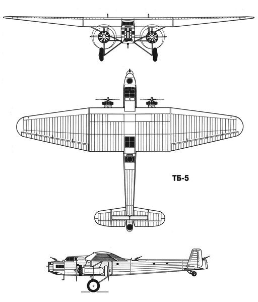
Be it this way or not, the documents confirm that in the spring of 1930 and practically without the traditional approvals, the TsKB-39 was given the task of building a heavy bomber that was named Airplane-8 or TsKB-8. The VVS however refer to the model under the designation TB-5 (Russian: Григорович ТБ-5).
The deficit in aluminum production seems consistent that the air forces had opted for the creation of a model built from more affordable materials.
By the early 1930s, a new “Sháraga” or Special Technical Bureau (OTB) of the OGPU dedicated to the development of aircraft engines had appeared in the Soviet correctional system. Noted builders such as BS Stiechkin, NR Brilling, AA Bessonov were there.
This group was given the task of designing, testing and producing a 24-cylinder engine that was known as FED (an acronym for Félix Edmúndovich Dzerzhinski). This engine with 4-row distribution in X and central injection system, had to develop a power of 1,100 – 1,250 hp at an altitude of 3,000 meters and its construction was directed by AA Bessonov. These values were considerable for the time.
The FED was conceived as the power plant for the new TB-5 bomber and its installation was planned in two variants: on the wing leading edge or in gondolas fixed to the wing intrados. Different situations led to the FED not being available at the established time, so the TB-5 had to be equipped with 4 Gnôme-Rhône 9Aq engines , a licensed copy of the excellent British Bristol Jupiter VI engine later built under license in the Zaparozhie Factory No.29 as M-22. The engines were located in tandem under each wing console. Despite the fact that the total power was almost similar to that calculated, the new drive installation had much more frontal resistance and the efficiency of the propeller was reduced by the tandem configuration, which had a negative impact on performance.
Practically all the personnel of the TsKB and a large part of the personnel of the VR Menzhinski Factory No.39 in Khodinka were mobilized for the work on TB-5, where Paufler’s “Sháraga” would be transferred from the Butirka prison.
Airplane-8 was built in just one year, which was record time for such a large and complex aircraft. Grigorovich in the same period, in parallel, worked on the IZ fighter. The appearance of both models in May 1931 (and the resounding success of the I-5) practically caused Grigorovich to receive amnesty.
The TB-5 was designed as a high-wing bomber with a double tail unit. Its construction was mixed, with little use of aluminum, a metal short in the USSR of those years.
The spacious fuselage featured a skeletal structure constructed from fabric-covered welded steel tubes. For ground transportation, the fuselage could be divided into three sections: the forward section to the wing trailing edge, the intermediate section to the beginning of the stabilizer, and the tail section.
The TB-5 wing featured a three-spar structure and constant rib pitch. The stringers were built with special profiles made of duralumin and tubes. The ribs were formed by stamping. The construction of the wing was quite complex, especially when it came to covering the fabric.
The airfoil selected was the R-II with 18% in the midplane area and 12% in the extremes. The wing had some small bracing supports that also helped to give the necessary rigidity to the power plant.
The tail was built on the basis of a fabric-covered aluminum frame. The horizontal plane presented a second, thinner unit, located at a greater height and called “stabiliron”, creating a kind of biplane box. Its function was to decrease the force on the joystick during landing operations and trim changes.
In the TB-5, on each side of the fuselage, under the wing, two 480 hp Gnôme-Rhône 9Aq engines were installed in tandem, so that they moved a propeller with two wooden blades in a driving configuration and another in a driving configuration. This engine would later be built under license under the designation M-22. In order to improve cooling, the rear engine was fitted with a Townend ring around the cylinder head.
The projected bomb load (with the use of the FED engines reached 2,500 kg) was located in an interior hold in the fuselage. DER-18 supports were located on the sides of this hold, allowing the crew to move freely inside the aircraft.
Defensive armament consisted of three TUR-5 turrets with paired Degtyaryov light machine guns for aircraft. The first of these turrets was located above the forward navigator’s position, just in front of the cockpit; the second just behind the wing and the third in the tail section of the fuselage. Apart from these positions in the bow there was a mobile firing tower, developed in the armament section under the direction of AV Nadashkievich. This can be considered the first Soviet attempt to obtain a remotely operated turret using mechanical and electrical controls.
This tower was built in the form of a cylindrical tank that rotated around its vertical axis. In the front part it had a slot that allowed the vertical displacement of the two machine guns. The horizontal movement of the machine guns was ensured by the rotation of the tower. The gunner was located inside the tower and if necessary, could leave it using a rear door towards the nose of the aircraft. For the first time in the USSR two PV-1 machine guns were installed here, built on the basis of the infantry Maxim, but using air cooling instead of water. For the first time, uninterruptible belt feeding was also used.
The rotation of the tower was carried out by means of an electrical system and the vertical movement of the machine gun was carried out by the shooter, located in a small seat.
Pilot and co-pilot were located in a closed cabin, with seats side by side. The crew of the TB-5 had some facilities that could be considered a novelty for the time: a toilet and four hammocks for resting.
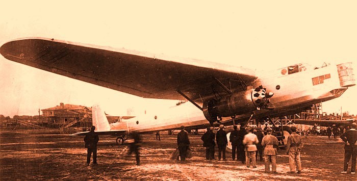
In the early summer of 1931 the TB-5 was first brought out onto the airfield. After engine tests and a few runs, the decision was made to allow the flight. On June 30, 1931, test pilot B. Buxgolts made the first test flight over Jodinka airfield.
After landing, Buxgolts came down from the cabin smiling and said:
By July 20, the plane had made four successful flights. With a weight of 11,200 kg and a fuel capacity of 1,850 kg, it had managed to cover a distance of 1,100 km during 6.7 hours of flight with an average speed of 162 km/h and a ceiling of 3,000 meters. Range with maximum fuel load of 2,410 kg and takeoff weight of 12,060 kg (including 500 kg of bombs) was 2,100 km. The maximum speed recorded was 180 km/h, the ceiling was 3,500 meters and the take-off run was about 400-420 meters.
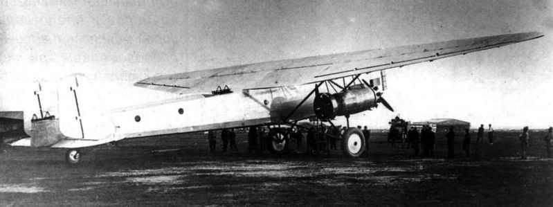
The performance obtained was not high, especially when compared to the Tupolev TB-3 bomber that had already been flying for a few months. The main cause of these results was the powertrain. The propellers used were more suitable for a fighter than for a bomber of that size. To make matters worse the rear propeller had to be shortened so that it could operate under the wing.
Despite these difficulties, the TB-5 presented a not insignificant set of advantages, among which stood out a better distribution of defensive weapons, better distribution of the bomb load on the plane, smaller dimensions and weights, much lower cost and simpler construction. The group of builders did not lose hope of being able to count on the promised FED engines, with which performance should be increased significantly. It should be noted that by the summer of 1931, Factory No.24 had 12 engines of this type in production and had aggregates and components for another 10 units.
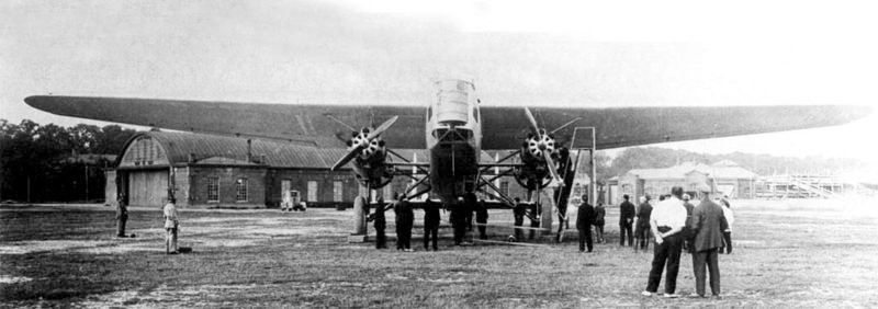
All these possibilities were evaluated and finally on July 25, 1931 the Labor and Defense Council (STO) asked the Pan-Soviet Aviation Union to prepare the conditions to produce six TB-5 bombers (one as a prototype of the series and the other 5 to perform military operation tests). Almost in parallel with this decision, these specimens were included in the plans for the formation of the new bomber squadrons for 1932.
The head of the VVS PI Baranov considered that, due to the delay presented by the FED engines, it was advisable to postpone the manufacture of the TB-5 copies for the year 1932 and he sent a request with these reasons to the United Council of the Economy of the USSR (VSNJ according to the initials of Vsiesoyuzni Soviet Narodnovo Jozyaistva). However, the chairman of the Council of People’s Commissars (SNK) VM Molotov had other ideas, so he ignored Baranov’s request and instead requested to take the necessary measures to speed up the construction of the series. According to M. Maslov the reasons for this decision could be of a political nature. The TB-5 bomber had been created within the OGPU and just a few days before, on July 6, 1931, this organization had given Stalin a demonstration of its achievements. There he was shown the I-5 fighter, the R-5 reconnaissance aircraft, the TSh-1 attack aircraft, the TB-5 bomber and the modern IZ gun-wielding fighter. Stalin was widely pleased and hinted that the OGPU leadership seemed to have succeeded in finding the most productive formula in aeronautical development. As a collateral consequence of this presentation, on August 27, 1931 the TsKB and the TsAGI would be unified under Czech control in the TsKB-TsAGI organization headed by Ye. S. Paufler.
During this time the TB-5 had received a significant group of improvements. In the month of June 1931, work was done on the structural reinforcement and the fixing system of the engines. The cockpits were fitted with upper access hatches, glazing was introduced in the midplane trailing edge area, the Townend ring was removed from the rear engines.
During the winter of 1931-1932 the bomber was prepared to operate with skis and several flights were made to analyze its behaviour. The design group was working on improving the conditions for installing the still awaited FED engines, but other variants of installing engines on the leading edge of the wing were analyzed. Works on this configuration were led by SA Kochierigin. Scale models with this configuration were tested in the TsAGI wind tunnel.
During this stage, other aeronautical constructors such as BI Cheranovski, VP Yatsenko and AN Refaeliants worked on the plane.
Unfortunately, the construction of the series could not be carried out, mainly because Factory No.39 was overloaded with the production of several experimental models.
The TB-5 flights continued and Soviet pilot MM Gromov would participate in them.
During one of the days of May 1932 and during a flight at a height of 800 meters a strong vibration began. The cause was that the left rear engine detached from the mounting bracket and the propeller broke the fuselage and embedded itself in a wooden bomb mock-up. The fuel caught fire.
Gromov ordered to shut off the fuel supply to the engines and began to glide with dives over the left wing to try to put out the fire. Eventually this was achieved and the pilot made a forced landing at Factory No.22 airfield in Fili. Only at this moment did they become aware that when the flames intensified the engineer AV Chesalov, who was in the wing area, had parachuted down to land without difficulty.
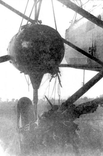
After this mishap, the TB-5 remained in Fili until December, without repairs being attempted. Grigorovich had switched to the development of fighters.
At the end of 1932, after verifying that the manufacture of the Túpolev TB-J bomber (military version of the ANT-14) was even more complicated than those of the TB-3, it was decided to return to the subject of the TB-5.
To assess the possibility of re-establishing the TB-5, a commission was created led by the representative of the TsAGI VN Chernishevich, who worked on December 1, 1932. As expected, the competing aircraft was harshly criticized: the aircraft was valued as overweight, with poor motor installation and design problems. On the other hand, the TB-5 had had its engines, part of the flight instruments, and weapons disassembled, and it was estimated that to give the bomber full flight capacity again, it would be necessary to invest 75 or 100 thousand rubles.
The commission considered that to improve the bomber it would be necessary to reinstall the engines on the wings, which would guarantee an increase in speed, which would reach 190-200 km and a ceiling of 4000 m, but the cost of the modifications would amount to 200 thousand rubles.
Incredibly, despite these assessments, it was decided to restore it with the proposed modifications, for which it would be returned to Factory No.39. A short time later, at a meeting of the VVS management, it was recognized that even with the modifications, the benefits of the TB-5 did not satisfy the requirements of the moment.
In the month of February 1933 the head of the GUAP Baranov instructed:
With this it all ended. TB-5 was not restored and its remains were handed over to the TsAGI structural resistance department. The Tupolev TB-J also did not see the light of day, as by the end of 1933 the specifications for bombers had grown considerably.
On the basis of the TB-5 in 1931 Chertverikov developed the reconnaissance flying boat MDR-3 or TsKB-11, which kept the design of the wing, tail and structural elements of the bomber. Finally, this design would not be produced either.
TB-5
Powerplant: 2 × 480 hp M-22 ( Bristol Jupiter VI
Wingspan: 31.00m
Wing area: 150.00 m²
Length: 22.10m
Height: 5.02m
Empty weight: 7483 kg
Normal takeoff weight: 12535 kg
Wing loading: 83.5 kg/ m²
Power Load: 7.0kg/hp
Fuel + lubricant capacity: 3300 kg
Top speed: 200km/h
Cruising speed: 182km/h
Range: 2100 km
Ceiling: 3500 m
Accommodation: 5 – 7
Armament: 3 x TUR-5 type turrets with paired Degtyaryov light machine guns / 1 x pair of PV-1 machine guns
Bombload: 1000 kg