In 1985, Bill Sadler and Bill Gewald began searching for a reliable four-stroke engine for ultralights and homebuilts. Sadler had developed the Sadler Vampire. He went on to design Formula 1 race cars and was an instructor at Massachusetts Institute of Technology.
Sadler teamed with the Gewalds to form the engine development company. Prior to that, the Gewalds operated two oil exploration air charter companies in Southeast Asia-one in North Borneo and the other in Singapore.
Sadler and the Gewalds began a worldwide search for an existing reliable four-stroke engine and found nothing to their liking. So they decided to invent and build one on their own.
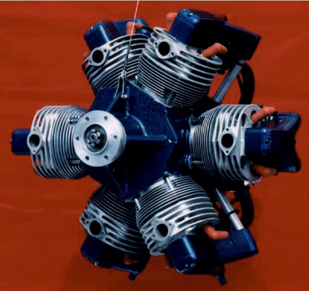
End result was the Sadler 6-cylinder radial engine with a four-cycle, dual electronic ignition with direct drive unit. Made with up-to-date materials and using modern computer numerically designed machinery, the engine has redundancy (12 spark plugs), low rpm, minimum vibration, low fuel consumption and low noise levels.
Patent No. 5,l50,670, was issued in 1992 and a total of 43 proof-of-concept engines were built, but none were offered for sale. According to Betty the company could not support the units with spare parts. However, the engine was installed in an Avid Model C where it produced a cruise speed of 85 mph, a 1,250 fpm rate of climb at gross weight, and a service ceiling above 12,500 feet. The engine, including electric starter and alternator, weighed 121.4 pounds and the all-up weight including engine mount, exhaust manifold and propeller was 162 lbs. There are almost 500 hours of dynamometer testing and the engine has also been successfully test flow on several different aircrafts.
The Sadler Radial Engine is a compact aircraft engine. The 6 cylinder R1765U radial uses two banks of three cylinders with power pulses every 120 degrees of revolution. The design uses VW cylinders and pistons for reliable inexpensive parts. Prototype testing has proven out this radial and casting patterns have been made. The engine is ready for final pre-production development.
Bill Gewald, who developed the engine from Sadler’s design, turned 75 and together with his wife Betty feels it is about time for younger, more energetic people to take charge.
The engine package being offered to investors included drawings, CAD programs, patterns, jigs and fixtures and many parts for the 65-hp R1765U engine. In addition, preliminary engineering and feasibility studies have been completed for 85-hp and 110-hp versions. Mrs. Gewald stated that only crankshafts and cylinder heads are needed to produce completed 65-hp engines. The “R” stands for “radial”, the “17” is “1721cc” displacement, the “65” is horsepower, and “U” means “uncertified”.
“We have never been able to raise enough money to go into full production, but we have all the drawings on autocad. We also have over $17,000 worth of patterns for all the proprietary parts,” she said. “It is a reliable, smooth, compact engine with low RPM (red-line is 3000 rpm) that runs beautifully on automotive fuel and sounds like a radial. They wanted to sell to someone with the financial resources to treat the engine with the TLC it deserves, and would accept the bulk of any payment based on sales royalties and will personally help all we can in production and sales.
The company had one engine running on a stand at the Arlington Airport north of Seattle that was available for demonstration the homebuilders with scaled-down replicas and others originally produced with radial engines.
So, if there is someone or a group out there wanting the challenge of producing a well-researched, out-of-the-ordinary engine design with the time-consuming R&D and basic tooling already complete, contact the Gewalds at Sadler Radial Engines, Inc, 603 NE 9th St., PO Box 953, Coupeville, WA 98239-0953.
This engine is quiet, even without a muffler, which stems not only from the slow-working pistons, but also the noise produced by the engine is at a frequency much lower than the high whine of the two-strokes.
The R1765U has a maximum width of 20.5″, a maximum height of 19.4″, and a length of approximately 17″ depending on starting configuration, carburetion and air cleaner.
There are two rows of three cylinders each, for a total of six cylinders. This arrangement gives a firing impulse every 120º or three power pulses per revolution. Each of the two, three-cylinder rows forms a system whose instantaneous mass-center or centroid, has an approximately circular locus that is exactly balanced by the equal and opposite mass-system of its adjacent cylinder row. In plain language, we can say that one cylinder row balances the other row all of the time.
The slight offset between the cylinder rows results in a dynamic imbalance or a “rocking couple” that is resolved along the aircraft longitudinal axis by the engine mounting system and a counter-weighted crankshaft.
The radial engine has excellent air-cooling characteristics. Each cylinder is individually exposed to its own flow of cooling air without the requirement for extensive baffling and ducting. The second cooling advantage this engine has is its low per-cylinder horsepower output making cooling demands very manageable. The pistons and cylinders are standard Volkswagen, extensively machined.
Individual cylinder heads are cast in 356 aluminum alloy heat-treated to T6. Cast iron valve seat insets are cast integrally with the head. Both inlet and exhaust valves are stainless steel VW racing types for durability and component availability. They ride in bronze valve guides pressed into the cylinder head. Valve springs need only exert a pressure of approximately 26 pounds at mid travel, thereby reducing wear and tear on the valve drive train.
A 5mm deep bathtub combustion chamber is used with a 2 mm quench height area above the piston. This allows for compression a ratio of 9.5 to 1 and the use of unleaded premium auto gasoline. Two spark plugs per cylinder are used to improve reliability as well as combustion efficiency.
The valve train uses only one single small diameter cam for all inlet valves and another identical cam to drive all the exhaust valves. Each tappet housing holds all of the six inlet or exhaust roller tappets. The hardened steel cams run on ball bearing integral shafts to drive the roller tappets. The tappet housings are staggered in the rear case and drive overlapping pushrods to each rocker arm. Because the valves are arranged in line lengthwise along the engine (placing exhaust forward and inlet rearward) and the pushrods all come out of the engine rear case in a single plane, each rocker arm for a given cylinder is displaced laterally to the left or right of the cylinder centerline. This allows the front exhaust rocker arm to miss the inlet valve and spring, as well as allowing the rear rocker arm to be similarly displaced from center, making room for the inlet manifold to pass between the push rods on its way to the cylinder head inlet port.
Valve timing has a minimum of overlap and duration to maximize low-end torque and provide useful horsepower in the 2900 rpm range. Valve cam accelerations have been kept low in the interest of low valve train stress and long life.
Full pressure lubrication is supplied from a rear case mounted oil feed pump running at camshaft speed. Inlet oil to the oil pump comes directly from a remote oil tank. A four-quart oil supply is recommended. Because the cylinder bases protrude into the crankcase cavity, very little back oil finds its way into the lower cylinders.
As originally tested, the engine had two completely independent electronic distributors driven from the rear case. Their shafts are mounted with individual gears that mesh with the main crankshaft time gear. Distributors are battery-coil type. Solid-state breakerless contact points are used to drive the standard coils to achieve optimum reliability and simplicity. An interesting feature of the radial engine is that the firing order proceeds sequentially around the cylinders in a direction opposite to the crankshaft rotation.
The inlet manifold system uses a circular cyclonic plenum chamber at the rear of the engine. Separate manifolds join this chamber to each cylinder’s inlet port. The carburetor is mounted centrally on the plenum box. A heat system can be fabricated using the engine’s exhaust as the heat source.
Configuration: Direct drive, 6 cylinder, four-cycle, internal combustion, gasoline fueled, free air cooled engine, one gravity fed carburetor, and a dry sump lubrication system.
Displacement: 1721cc (105 cu in.)
HP/Torque @ 3000 rpm: 65 hp/113.4
Stroke: 50 mm (1.969 in.)
Bore: 85.5 mm (3.366 in.)
Rotation: clockwise, view from rear
Compression Ratio: 9.5:1
Option: Electric start
Accessories: oil cooler, oil tank (4 quart)
Engine weight with components (dry): 108 lb (Prop. Start)
Engine weight with electric start/alternator systems: 122 lb
Engine diameter: 20.7 in plus oil system components below engine
Performance (With 66″ 2 Blade, Wood Prop.)
Normal rated power, T.O: 62 bhp @ 2,850 rpm
Max. rated power 65 bhp @ 2,975 rpm
Continuous rated power (90%): 58.5 bhp
90% pwr fuel burn: 4.1 USgph / spc=.44 lb./bhp-hr
Typical cruise power (75%): 49.5 bhp
75% pwr fuel burnL 3.4 USgph or spc=.43 lb./bhp-hr
Idle Speed: 800 rpm